
Related Manuals for Woodland Mills Woodlander XL


Summary of Contents for Woodland Mills Woodlander XL
- Page 1 WOODLANDER XL SAWMILL TRAILER ™ OPERATOR’S MANUAL The Woodlander ™ XL is compatible with HM126, HM130 & HM130MAX sawmills. Woodlander ™ is a trademark of Woodland Mills, Inc.
- Page 2 This page intentionally left blank.
-
Page 3: Table Of Contents
Woodlander ™ XL Operator's Manual TABLE OF CONTENTS TABLE OF CONTENTS ___________________________________ INTRODUCTION _________________________________________ GENERAL SAFETY RULES _______________________________ INSPECTION/MAINTENANCE ______________________________ TECHNICAL SPECIFICATIONS ____________________________ BOLT TORQUE SPECIFICATIONS _____________________________ TRAILER ASSEMBLY ____________________________________ 1. TOOLS REQUIRED ______________________________________ 2. UNPACKING ____________________________________________ 3. TRACK RAILS, JOINING GUSSETS, MIDDLE BUNK ____________ 4. - Page 4 Woodlander ™ XL Operator's Manual NORTH AMERICAN PARTS LIST __________________________ EUROPEAN PARTS LIST ________________________________ EXPLODED VIEWS _____________________________________ COMPLETE ASSEMBLY ____________________________________ CHASSIS AND TRACK ______________________________________ TONGUE _________________________________________________ NORTH AMERICA _____________________________________________ EUROPE ______________________________________________________ AXLES, WHEELS, AND FENDERS ____________________________ LIGHTING ________________________________________________ NORTH AMERICA _____________________________________________ EUROPE ______________________________________________________...
-
Page 5: Introduction
If you have any questions relative to a particular application, DO NOT use the trailer until you have first contacted Woodland Mills to determine if it can or should be performed using the product. -
Page 6: General Safety Rules
Woodlander ™ XL Operator's Manual **SAVE THESE INSTRUCTIONS** GENERAL SAFETY RULES WARNING! Read and understand all instructions. Failure to follow all instructions listed below may result serious injury. WARNING! The warnings, cautions, and instructions discussed in this instruction manual cannot cover all possible conditions or situations that could occur. -
Page 7: Technical Specifications
Woodlander ™ XL Operator's Manual TECHNICAL SPECIFICATIONS Item Specification Trailer Axle Independent Torsion Axle Design Trailer Wheels 5 Bolts @ 4.5” (114 mm) & 5.30-12 DOT Approved Tires Tire Pressure Refer to Tire Wheel Nut Torque 80 ft•lb / 110 N•m Trailer Ball Coupler 2”... -
Page 8: Trailer Assembly
Woodlander ™ XL Operator's Manual TRAILER ASSEMBLY 1. TOOLS REQUIRED Tool Specification Phillips Head Screwdriver No. 3 Wrench/Socket 8 mm Wrench/Socket 9 mm Wrench/Socket 10 mm Wrench/Socket 13 mm Wrench/Socket 14 mm Wrench/Socket 15 mm Wrench/Socket 18 mm Adjustable Wrench Variable Torque Wrench Capable of 93 ft•lb (126 N•m) -
Page 9: Unpacking
Woodlander ™ XL Operator's Manual 2. UNPACKING Remove all the parts from the steel crate. Set the crate aside as it will be used as a support for several of the following steps. WDLRXL-MY2020: Rev A Page 27-Sep-2019... -
Page 10: Track Rails, Joining Gussets, Middle Bunk
Woodlander ™ XL Operator's Manual 3. TRACK RAILS, JOINING GUSSETS, MIDDLE BUNK Using the hardware listed below, assemble the gussets to the track as shown on the next page. Torque all bolts per the table in section BOLT TORQUE SPECIFICATIONS. M10 X 30 mm Flanged Hex Middle Bunk... - Page 11 Woodlander ™ XL Operator's Manual WDLRXL-MY2020: Rev A Page 27-Sep-2019...
-
Page 12: Long Side Plates, Joining Gussets
Woodlander ™ XL Operator's Manual 4. LONG SIDE PLATES, JOINING GUSSETS Using the hardware listed below, hang the long side plates on the centre track section. Snug the bolts up, but leave them loose enough to move the plates. M10 X 30 mm Long Side Flanged Hex Plate... - Page 13 Woodlander ™ XL Operator's Manual WDLRXL-MY2020: Rev A Page 27-Sep-2019...
-
Page 14: Track Rails, End Bunks, End Gussets
Woodlander ™ XL Operator's Manual 5. TRACK RAILS, END BUNKS, END GUSSETS Using the hardware listed below, add the remaining track sections and end bunks. Leave the bolts loose. M10 X 30 mm Flanged Hex End Bunk Bolt M10 Flanged End Gusset Lock Nut Track Rail... - Page 15 Woodlander ™ XL Operator's Manual WDLRXL-MY2020: Rev A Page 27-Sep-2019...
-
Page 16: Jack Stands [Temporary]
Woodlander ™ XL Operator's Manual 6. JACK STANDS [TEMPORARY] Using 4 jack stands, place 2 under each end bunk and level the assembly. Measure diagonally to check for squareness. Tighten all of the vertical track rail bolts. Leave the horizontal bolts that pass through the side plates loose. -
Page 17: Joining Bunks, Joining Gussets
Woodlander ™ XL Operator's Manual 7. JOINING BUNKS, JOINING GUSSETS Using the hardware listed below, install the joining bunks and joining gussets. Use the M10 X 40 mm bolts through the bunks and the M10 X 30 bolts in the side plates. Tighten all the bolts in this step. - Page 18 Woodlander ™ XL Operator's Manual M10 X 40 mm through top. M10 X 30 mm through side. WDLRXL-MY2020: Rev A Page 27-Sep-2019...
-
Page 19: Middle Bunks, Joining Gussets
Woodlander ™ XL Operator's Manual 8. MIDDLE BUNKS, JOINING GUSSETS Using the hardware below, install the remaining bunks and gussets. Tighten the bolts in this step. M10 X 30 mm Flanged Hex Middle Bunk Bolt M10 Flanged Joining Gusset Lock Nut WDLRXL-MY2020: Rev A Page 27-Sep-2019... - Page 20 Woodlander ™ XL Operator's Manual WDLRXL-MY2020: Rev A Page 27-Sep-2019...
-
Page 21: Short Side Plates, Carriage Stops
Woodlander ™ XL Operator's Manual 9. SHORT SIDE PLATES, CARRIAGE STOPS Using the hardware listed below, install the short side plate and carriage stops. The M10 X 35 mm bolts are used at the 4 carriage stop locations. Tighten all of the side plate bolts starting from the centre moving outward. - Page 22 Woodlander ™ XL Operator's Manual M10 X 30 mm through side. M10 X 35 mm at carriage stops. WDLRXL-MY2020: Rev A Page 27-Sep-2019...
- Page 23 Woodlander ™ XL Operator's Manual With all of the bolts now tightened, lower the jacks so that the assembly is resting on the crate. WDLRXL-MY2020: Rev A Page 27-Sep-2019...
-
Page 24: Cross Beams, Jack Mounts [Ends]
Woodlander ™ XL Operator's Manual 10. CROSS BEAMS, JACK MOUNTS [ENDS] Using the hardware listed below, install the front and rear jack mounts including 1 cross beam with each pair of mounts. Tighten all bolts. Install jack stands on the jack mounts. M10 X 35 mm Flanged Hex Cross Beam... - Page 25 Woodlander ™ XL Operator's Manual WDLRXL-MY2020: Rev A Page 27-Sep-2019...
- Page 26 Woodlander ™ XL Operator's Manual Next, raise the assembly as high as the jacks stands will permit. Pull the crate out from under the assembly once it is sufficiently high enough. It may be necessary to place a block of wood under each jack foot to achieve a sufficient height.
-
Page 27: Cross Beam, Jack Mounts [Centre]
Woodlander ™ XL Operator's Manual 11. CROSS BEAM, JACK MOUNTS [CENTRE] Using the hardware below, install the centre cross beam and jack mounts. Level the trailer on all six jack stands. Tighten all the bolts. M10 X 35 mm Flanged Hex Cross Beam Bolt M10 Flanged... - Page 28 Woodlander ™ XL Operator's Manual WDLRXL-MY2020: Rev A Page 27-Sep-2019...
-
Page 29: Cross Beams, Axle Cross Beam, Axle Mounts
Woodlander ™ XL Operator's Manual 12. CROSS BEAMS, AXLE CROSS BEAM, AXLE MOUNTS Using the hardware listed below, install the remaining cross beams, the front cross beam (with 2 holes), and axle mount cross beam in the locations shown below. Tighten all bolts. M10 X 35 mm Axle Mount w/ Flanged Hex... - Page 30 Woodlander ™ XL Operator's Manual Left Axle Mount Right Axle Mount Note orientation: Fender mount Note orientation: Fender mount sleeve towards rear of trailer sleeve towards rear of trailer Thread knob into Axle Use M10 X 35 mm Mount prior to bolting to bolts for left and side plate right axle mounts...
-
Page 31: Axles
Woodlander ™ XL Operator's Manual 13. AXLES Using the hardware listed below, install the axles as shown on the next page. Tighten these bolts to the specified torque. Place a bubble level across both axles and check for level. If the level is off, use axle shim plates between the inner axle mounting face and axle cross beam to ensure the axles ride level. - Page 32 Woodlander ™ XL Operator's Manual Install up to 3 shim plates per axle if necessary to level axles. Only use if axles require levelling. Axle swingarms point towards rear of trailer. WDLRXL-MY2020: Rev A Page 27-Sep-2019...
-
Page 33: Wheels
Woodlander ™ XL Operator's Manual 14. WHEELS Using the hardware listed below, install the wheels on the axles. Using a torque wrench, torque the lug nuts to 80 ft•lb / 110 N•m following the pattern shown below. 5.30-12 Wheel 1/2-20 in Lug Nut WDLRXL-MY2020: Rev A Page 27-Sep-2019... -
Page 34: Fenders
Woodlander ™ XL Operator's Manual 15. FENDERS Using the hardware listed below, assemble the fenders to the fender brackets. Tighten these bolts. Slide the post on the fender bracket into the sleeve on the axle mount and insert the locking pin through the hole located at the bottom of the fender bracket post. Secure the fender/ fender bracket sub-assembly using the M10 X 30 mm knob by threading it into the axle mount until tight. - Page 35 Woodlander ™ XL Operator's Manual Some components removed for clarity WDLRXL-MY2020: Rev A Page 27-Sep-2019...
-
Page 36: Tongue, Hitch Coupler
Woodlander ™ XL Operator's Manual 16. TONGUE, HITCH COUPLER Using the hardware listed below, install the trailer tongue and hitch coupler. Don’t tighten the M10 X 160 mm bolts in this step since the plug for the lights will be routed through the tongue in the following step. - Page 37 Woodlander ™ XL Operator's Manual Europe M12 X 100 mm North America M12 X 70 mm M10 X 160 mm Side plate removed for clarity. WDLRXL-MY2020: Rev A Page 27-Sep-2019...
-
Page 38: Lighting
Woodlander ™ XL Operator's Manual 17. LIGHTING Using the hardware listed below, install the light bar and country appropriate wire harness. Secure tail lights to the light bar using M5 flanged lock nuts before mounting light bar to trailer. Use cable clamps to secure wire harness to side plates down right-side of trailer. Tighten all bolts. - Page 39 Woodlander ™ XL Operator's Manual Cable Clamp locations (12x) M5 X 20 mm Pan Head M5 Lock Nut M8 X 25 mm M5 X 20 mm Europe Only Pan Head Note: tail lights (North America and Europe) and side lights (North America only) are integral to the wire harness.
- Page 40 Woodlander ™ XL Operator's Manual Europe Only Route wire harness through tongue prior to tightening M10 X 160 mm bolts M5 X 20 mm Pan Head M6 X 20 mm There are 2 cable clamps per short side plate (2) and 4 per long side plate (2) for a total of 12. Cable clamps are installed down the right-hand side of the trailer only.
-
Page 41: Badges
Woodlander ™ XL Operator's Manual 18. BADGES Using the hardware listed below, install the two (2) Woodlander badges as shown. M6 X 20 mm Hex Woodlander Bolt Badge M6 Flat Washer M6 Lock Nut WDLRXL-MY2020: Rev A Page 27-Sep-2019... - Page 42 Woodlander ™ XL Operator's Manual WDLRXL-MY2020: Rev A Page 27-Sep-2019...
-
Page 43: Safety Chain
Woodlander ™ XL Operator's Manual 19. SAFETY CHAIN Using the hardware below, install the safety chain on the trailer tongue. This step is not needed for European customers. M10 X 40 mm Safety Chain Hex Bolt (Not in (Not in Europe) Europe) M10 Flat... -
Page 44: Head Lock-Down Plates
Woodlander ™ XL Operator's Manual 20. HEAD LOCK-DOWN PLATES Place the assembled sawhead on the trailer. Using the hardware listed below, install the head lock down plates as shown on the next page. Tighten these bolts to the specified torque. M6 X 40 mm Hex Bolt M6 X 25 mm... - Page 45 Woodlander ™ XL Operator's Manual Remove the eight (8) spacers from the carriage wheel axles and discard the four (4) short spacers. Only the four (4) tall spacers will be reused in the next steps. Discard short spacers Using the provided M6 X 40 mm and M6 X 25 mm bolts, install the lock-down plates in place of the short spacers with the taller spacer sandwiched between.
- Page 46 Woodlander ™ XL Operator's Manual Drill four (4) holes for the lock-down plates using the provided ⅜ in drill bit. Measure 19 in [48 cm] from the rear edge of the track rail (not the carriage stop) to the rear post of the sawhead. Insert a locking pin into each hole as they are drilled.
- Page 47 Woodlander ™ XL Operator's Manual NORTH AMERICAN PARTS LIST Quantity Item Part No. Description HM126 HM130 HM130 0001373 GUSSET, END 0001374 GUSSET, JOINING 0001363 SIDE PLATE, LONG 0001364 SIDE PLATE, SHORT 0001369 CROSS BEAM 0002900 CROSS BEAM, MAX 0001370 CROSS BEAM, FRONT 0002899 CROSS BEAM, FRONT, MAX 0001385...
- Page 48 Woodlander ™ XL Operator's Manual Quantity Item Part No. Description HM126 HM130 HM130 HEX BOLT, FLANGED, M12 X 1.75, 35 mm LG SCREW, PPH, M5 X 0.8, 20 mm LG FLAT WASHER, M6 FLAT WASHER, M10 LOCK NUT, M6 X 1 LOCK NUT, M10 X 1.5 LOCK NUT, M12 X 1.75 LOCK NUT, FLANGED, M5 X 0.8...
- Page 49 Woodlander ™ XL Operator's Manual EUROPEAN PARTS LIST Quantity Item Part No. Description HM126 HM130 HM130 0001373 GUSSET, END 0001374 GUSSET, JOINING 0001363 SIDE PLATE, LONG 0001364 SIDE PLATE, SHORT 0001369 CROSS BEAM 0002900 CROSS BEAM, MAX 0001370 CROSS BEAM, FRONT 0002899 CROSS BEAM, FRONT, MAX 0001385...
- Page 50 Woodlander ™ XL Operator's Manual Quantity Item Part No. Description HM126 HM130 HM130 HEX BOLT, FLANGED, M10 X 1.5, 35 mm LG HEX BOLT, FLANGED, M10 X 1.5, 40 mm LG HEX BOLT, FLANGED, M12 X 1.75, 35 mm LG SCREW, PPH, M5 X 0.8, 20 mm LG FLAT WASHER, M6 FLAT WASHER, M10...
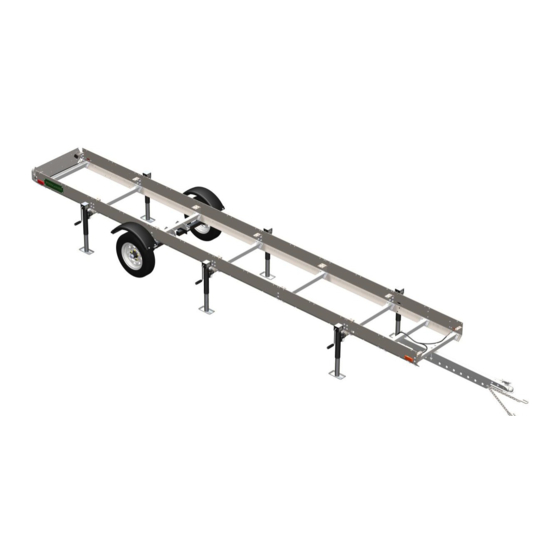
- Page 51 Woodlander ™ XL Operator's Manual EXPLODED VIEWS COMPLETE ASSEMBLY WDLRXL-MY2020: Rev A Page 27-Sep-2019...
- Page 52 Woodlander ™ XL Operator's Manual CHASSIS AND TRACK WDLRXL-MY2020: Rev A Page 27-Sep-2019...
-
Page 53: North America
Woodlander ™ XL Operator's Manual TONGUE NORTH AMERICA 50 2X 52 2X EUROPE 50 2X 50 2X 52 2X 52 2X WDLRXL-MY2020: Rev A Page 27-Sep-2019... - Page 54 Woodlander ™ XL Operator's Manual AXLES, WHEELS, AND FENDERS WDLRXL-MY2020: Rev A Page 27-Sep-2019...
- Page 55 Woodlander ™ XL Operator's Manual LIGHTING NORTH AMERICA 54 2X 54 2X 54 2X 43 4X 43 4X 43 4X WDLRXL-MY2020: Rev A Page 27-Sep-2019...
-
Page 56: Europe
Woodlander ™ XL Operator's Manual EUROPE 54 2X 43 4X WDLRXL-MY2020: Rev A Page 27-Sep-2019... - Page 57 Woodlander ™ XL Operator's Manual BADGES WDLRXL-MY2020: Rev A Page 27-Sep-2019...
- Page 58 Woodlander ™ XL Operator's Manual HEAD LOCK-DOWN PLATES WDLRXL-MY2020: Rev A Page 27-Sep-2019...
-
Page 59: Notes
Woodlander ™ XL Operator's Manual NOTES WDLRXL-MY2020: Rev A Page 27-Sep-2019... - Page 60 Woodlander ™ XL Operator's Manual WDLRXL-MY2020: Rev A Page 27-Sep-2019...
- Page 61 Woodlander ™ XL Operator's Manual WDLRXL-MY2020: Rev A Page 27-Sep-2019...
- Page 62 Woodlander ™ XL Operator's Manual WDLRXL-MY2020: Rev A Page 27-Sep-2019...
- Page 63 This page intentionally left blank.
Need help?
Do you have a question about the Woodlander XL and is the answer not in the manual?
Questions and answers