
Related Manuals for Woodland Mills Multilander Logging Trailer with Utility Box


Summary of Contents for Woodland Mills Multilander Logging Trailer with Utility Box
- Page 1 MULTILANDER ACCESSORY ™ UTILITY BOX OPERATOR’S MANUAL Multilander ™ is a trademark of Woodland Mills, Inc.
- Page 2 This page intentionally left blank.
-
Page 3: Table Of Contents
Multilander ™ Operator’s Manual TABLE OF CONTENTS TABLE OF CONTENTS _______________________________________ CONFIGURATIONS & ACCESSORIES ___________________________ TECHNICAL SPECIFICATIONS _________________________________ BOLT TORQUE SPECIFICATIONS _________________________________ OVERALL DIMENSIONS _________________________________________ OVERALL DIMENSIONS—WITH TRAILER __________________________ UTILITY BOX ASSEMBLY _____________________________________ 1. TOOLS REQUIRED __________________________________________ 2. UNPACKING _______________________________________________ 3. -
Page 4: Configurations & Accessories
The Multilander Logging Trailer is available in five (5) configurations shown below. Each configuration can be further customized with additional accessories such as a cant hook mount, a ball mount hitch kit, and a universal mounting kit. Contact Woodland Mills or visit our website for information and pricing. 1. LOGGING TRAILER 3. -
Page 5: Technical Specifications
Multilander ™ Operator’s Manual TECHNICAL SPECIFICATIONS Item Specification Construction/Finish Powder-Coated Steel Tubing & 16 GA Check Plate Hauling Capacity 2000 lb [907 kg] Box Volume 206 gal [781 L] - 1 cubic yard Box Outside Dims 84-1/16 in [2135 mm] L x 42-3/16 in [1071 mm] W x 22-1/2 in [572 mm] H Overall Length 106-½... -
Page 6: Overall Dimensions
Multilander ™ Operator’s Manual OVERALL DIMENSIONS Utility Box Capacity: 1 yd MLTRUB-MY2020: Rev A Page 21-Aug-2019... -
Page 7: Overall Dimensions-With Trailer
Multilander ™ Operator’s Manual OVERALL DIMENSIONS—WITH TRAILER Multilander trailer with Utility Box in its most compact configuration: • Narrowest track width (48 in) • Shortest tongue extension (103-½ inch overall length) MLTRUB-MY2020: Rev A Page 21-Aug-2019... -
Page 8: Utility Box Assembly
Multilander ™ Operator’s Manual UTILITY BOX ASSEMBLY 1. TOOLS REQUIRED Tool Specification Wrench/Socket 8 mm Wrench/Socket 9 mm Wrench/Socket 10 mm Wrench/Socket 13 mm Wrench/Socket 14 mm Wrench/Socket 15 mm Wrench/Socket 18 mm Hex Key Set of Metric Hex Keys (e.g. 2-10 mm) Adjustable Wrench Variable Torque Wrench... -
Page 9: Unpacking
Multilander ™ Operator’s Manual 2. UNPACKING The Multilander utility box ships in a metal frame crate with a cardboard cover. Lift off the cover and remove all the fasteners along the bottom edge of the front/rear of the skid as indicated below. -
Page 10: Side Walls
Multilander ™ Operator’s Manual 3. SIDE WALLS Using the hardware listed below, assemble the two (2) side walls together. Do not tighten any hardware until instructed during the final assembly step. M12 X 120 mm Flanged Hex Right Side Wall Bolt M10 X 110 mm Flanged Hex... - Page 11 Multilander ™ Operator’s Manual Assembly of the utility box is easiest when built upside down. Turn both side walls upside down and align the holes running down the spine using the five (5) M10 X 100 mm bolts and M10 lock nuts as shown below.
- Page 12 Multilander ™ Operator’s Manual Ensure all bolts are just finger tight. Over-tightening could prevent part alignment during the next assembly steps. MLTRUB-MY2020: Rev A Page 21-Aug-2019...
-
Page 13: Tailgate Frame
Multilander ™ Operator’s Manual 4. TAILGATE FRAME Using the hardware listed below, assemble the tailgate frame to the side walls. Do not tighten any hardware until instructed during the final assembly step. M10 X 70 mm M10 Flanged Button Head Lock Nut Screw M10 X 60 mm... - Page 14 Multilander ™ Operator’s Manual With the tailgate frame in position, insert the four (4) M10 X 70 mm screws, washers, and lock nuts along the bottom of the tailgate frame as shown below-left. Then insert six (6) M10 X 60 mm screws, washers, and lock nuts through the bottom faces of the side walls and then through the tailgate frame as shown below-right.
- Page 15 Multilander ™ Operator’s Manual Insert the final two (2) M10 X 60 mm screws, washers, and lock nuts through the lower side face of each wall. Insert the four (4) M10 X 25 mm screws, washers, and lock nuts through the upper side faces of both walls.
-
Page 16: Hinge Plates
Multilander ™ Operator’s Manual 5. HINGE PLATES Using the hardware listed below, assemble the hinge plates to the bottom of the side walls. Torque all four (4) bolts per the table in section, BOLT TORQUE SPECIFICATIONS. M10 X 80 mm Flanged Hex Hinge Plate Bolt... -
Page 17: Front Wall
Multilander ™ Operator’s Manual 6. FRONT WALL Using the hardware listed below, assemble the front wall to the side walls. Do not tighten any hardware until instructed at the end of this step. M10 X 60 mm M10 Flat Button Head Washer Screw M10 Flanged... -
Page 18: Tailgate
Multilander ™ Operator’s Manual 7. TAILGATE Using the hardware listed below, assemble the hook latches and tailgate to the side walls. M5 X 12 mm Button Head Hook Latch Screw M5 Lock Nut Tailgate Assemble the two (2) hook latches to the brackets on each side wall using two (2) M5 X 12 mm screws and lock nuts per latch. - Page 19 Multilander ™ Operator’s Manual With assembly of the utility box complete, rotate it 180° until it is sitting right-side up. Two (2) locking pins come pre-assembled to the tailgate which are used to engage/disengage it with/from the utility box. By default the pins are in the engaged position. Each pin is pulled towards the centre of the tailgate until it no longer protrudes in order to disengage them as shown below.
- Page 20 Multilander ™ Operator’s Manual To install the tailgate, disengage both locking pins. Position the top of the tailgate until the locking pins line up with the holes at the top of each side wall. Release the pins so they fully engage with the side walls and then rotate the tailgate down into position.
- Page 21 Multilander ™ Operator’s Manual Secure the tailgate to the utility box with the two (2) hook latches at the bottom of each side wall. Connect the hook to the slot in the rear of the tailgate (see #1 below) and then close the latch (see #2 below).
-
Page 22: Utility Box To Trailer
Multilander ™ Operator’s Manual 8. UTILITY BOX TO TRAILER After assembly of the utility box is complete, mate it to the Multilander trailer using the hardware listed below. M10 Flanged Lock-Down Lock Nut Clamp U-Bolt Lock-Down Clamp Remove both linch pins and hinge pins from the hinge brackets on the rear log rack of the Multilander trailer. - Page 23 Multilander ™ Operator’s Manual With the assistance of another person, carry the utility box over to the trailer and set it down onto the log racks. Align the hinge holes in the utility box with those on the trailer making sure the hinge plates on the utility box sit inside the log rack hinges as shown in the detail below.
- Page 24 Multilander ™ Operator’s Manual STOP! If either the boom and winch were purchased, ignore this section. This page is for owners with the Multilander Trailer with Utility Box configuration only—if there is no winch and boom kit with your Multilander, follow the instructions on this page.
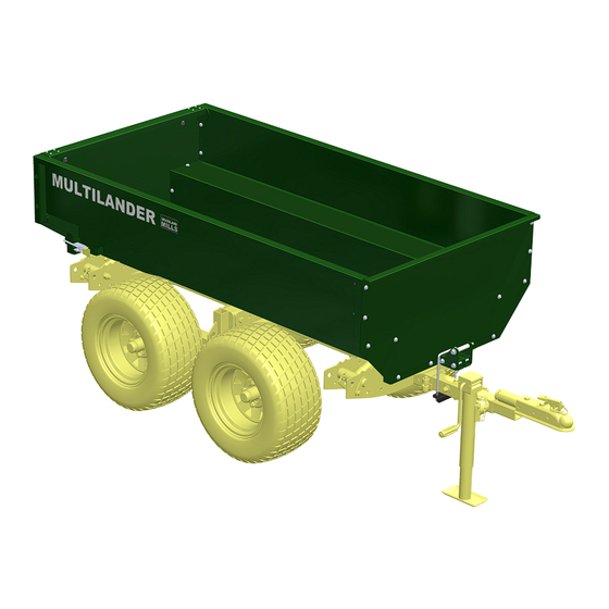
- Page 25 Multilander ™ Operator’s Manual Multilander Logging Trailer with Utility Box configuration shown below. Multilander Logging Trailer with Utility Dump Box configuration shown below. Boom and winch kit solid separately. MLTRUB-MY2020: Rev A Page 21-Aug-2019...
-
Page 26: Parts List
Multilander ™ Operator’s Manual PARTS LIST Item Part No. Description 0002328 SIDE WALL, RIGHT 0002329 SIDE WALL, LEFT 0002330 FRONT WALL 0002331 TAILGATE FRAME 0002332 TAILGATE 0002333 SPACER PLATE 0002334 LIFTING PLATE 0002335 WINCH HOOK COLLAR 0002336 HINGE PLATE 0002337 LOCK PIN ASSEMBLY, 12 mm DIA 0002338 HOOK LATCH, 8 mm HOOK... -
Page 27: Exploded Assembly Views
Multilander ™ Operator’s Manual EXPLODED ASSEMBLY VIEWS SIDE WALLS MLTRUB-MY2020: Rev A Page 21-Aug-2019... -
Page 28: Tailgate Frame
Multilander ™ Operator’s Manual TAILGATE FRAME MLTRUB-MY2020: Rev A Page 21-Aug-2019... -
Page 29: Hinge Plates
Multilander ™ Operator’s Manual HINGE PLATES MLTRUB-MY2020: Rev A Page 21-Aug-2019... -
Page 30: Front Wall
Multilander ™ Operator’s Manual FRONT WALL MLTRUB-MY2020: Rev A Page 21-Aug-2019... -
Page 31: Tailgate
Multilander ™ Operator’s Manual TAILGATE MLTRUB-MY2020: Rev A Page 21-Aug-2019... -
Page 32: Lock-Down Clamp
Multilander ™ Operator’s Manual LOCK-DOWN CLAMP MLTRUB-MY2020: Rev A Page 21-Aug-2019... -
Page 33: Notes
Multilander ™ Operator’s Manual NOTES MLTRUB-MY2020: Rev A Page 21-Aug-2019... - Page 34 Multilander ™ Operator’s Manual MLTRUB-MY2020: Rev A Page 21-Aug-2019...
- Page 35 This page intentionally left blank.
Need help?
Do you have a question about the Multilander Logging Trailer with Utility Box and is the answer not in the manual?
Questions and answers