
Related Manuals for Woodland Mills MULTILANDER


Summary of Contents for Woodland Mills MULTILANDER
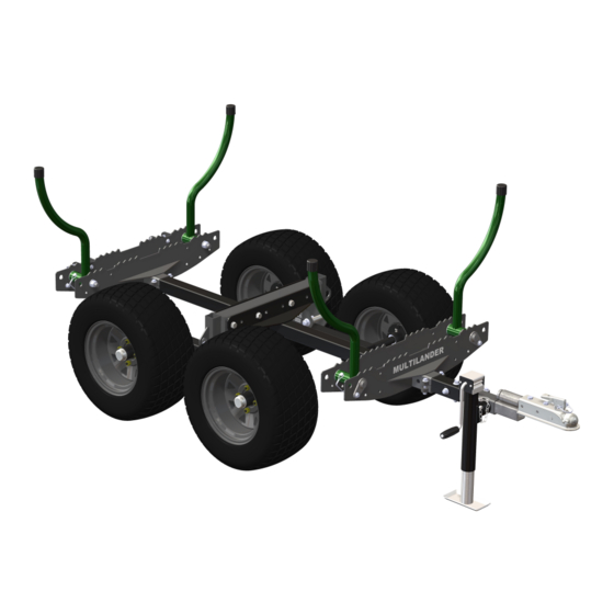
- Page 1 MULTILANDER TRAILER ™ OPERATOR’S MANUAL Multilander ™ is a trademark of Woodland Mills, Inc.
- Page 2 This page intentionally left blank.
-
Page 3: Table Of Contents
Multilander ™ Operator’s Manual TABLE OF CONTENTS TABLE OF CONTENTS ___________________________________ INTRODUCTION _________________________________________ GENERAL SAFETY RULES _______________________________ INSPECTION/MAINTENANCE ______________________________ CONFIGURATIONS & ACCESSORIES _______________________ TECHNICAL SPECIFICATIONS ____________________________ BOLT TORQUE SPECIFICATIONS ____________________________ OVERALL DIMENSIONS—MIN _______________________________ OVERALL DIMENSIONS—MAX ______________________________ TRAILER ASSEMBLY ____________________________________ 1. TOOLS REQUIRED _____________________________________ 2. - Page 4 Multilander ™ Operator’s Manual OPERATION ___________________________________________ LOGGING ARMS _________________________________________ JACK STAND ____________________________________________ MAINTENANCE ________________________________________ GREASE POINTS ________________________________________ PARTS LIST ___________________________________________ EXPLODED ASSEMBLY VIEWS ___________________________ CHASSIS _______________________________________________ WALKING BEAMS ________________________________________ LOG RACKS _____________________________________________ LOG RACKS—INSTALLED _________________________________ TONGUE & JACK STAND __________________________________...
-
Page 5: Introduction
If you have any questions relative to a particular application, DO NOT use the trailer until you have first contacted Woodland Mills to determine if it can or should be performed using the product. -
Page 6: General Safety Rules
Multilander ™ Operator’s Manual **SAVE THESE INSTRUCTIONS** GENERAL SAFETY RULES WARNING! Read and understand all instructions. Failure to follow all instructions listed below may result serious injury. WARNING! The warnings, cautions, and instructions discussed in this instruction manual cannot cover all possible conditions or situations that could occur. -
Page 7: Configurations & Accessories
The Multilander Logging Trailer is available in five (5) configurations shown below. Each configuration can be further customized with additional accessories such as a cant hook mount, a ball mount hitch kit, and a universal mounting kit. Contact Woodland Mills or visit our website for information and pricing. 1. LOGGING TRAILER 3. -
Page 8: Technical Specifications
Multilander ™ Operator’s Manual TECHNICAL SPECIFICATIONS Item Specification Construction/Finish Powder-Coated/Galvanized Tube & Plate Steel Axle Walking Beam Wheels & Tires 4 Bolts @ 4” [101.6 mm] & 23x10.5-12 Tires Tire Pressure Refer to Tire Wheel Nut Torque 80 ft•lb [110 N•m]... -
Page 9: Overall Dimensions-Min
Multilander ™ Operator’s Manual OVERALL DIMENSIONS—MIN Multilander trailer in its most compact configuration: • Narrowest track width: 48 in • Shortest tongue extension: 103-½ inch overall length • Logging arms stowed MLTR-MY2020-EN: Rev B Page 22-Jan-2021... -
Page 10: Overall Dimensions-Max
Multilander ™ Operator’s Manual OVERALL DIMENSIONS—MAX Multilander trailer in its most expanded configuration: • Widest track width: 60 in • Longest tongue extension: 151-½ inch overall length • Logging arms up MLTR-MY2020-EN: Rev B Page 22-Jan-2021... -
Page 11: Trailer Assembly
Multilander ™ Operator’s Manual TRAILER ASSEMBLY 1. TOOLS REQUIRED Tool Specification Wrench/Socket 8 mm Wrench/Socket 9 mm Wrench/Socket 10 mm Wrench/Socket 13 mm Wrench/Socket 14 mm Wrench/Socket 15 mm Wrench/Socket 18 mm Adjustable Wrench Variable Torque Wrench Capable of 161 ft•lb (218 N•m) -
Page 12: Unpacking
Operator’s Manual 2. UNPACKING The Multilander trailer ships in a metal frame crate with a cardboard cover. Lift off the cover and remove all the fasteners along the bottom edge of the front/rear of the skid as indicated below. Lift the top crate frame off the bottom skid and remove all the components and boxes. Set the crate aside as it can be used as a support for several of the assembly steps. -
Page 13: Chassis & Index Tubes
The Index Tube Assembly is comprised of an outer and inner sleeve that telescope together, each with a series of holes that allows the Multilander to be configured to one of four (4) predetermined track widths: 48, 56, 58, and 60 inches. - Page 14 Multilander ™ Operator’s Manual Pull the index tubes apart enough so they will clear the mounting brackets when nested down into the chassis and then push them back together: REAR Front end of chassis can be identified by the two large tongue...
-
Page 15: Inch Track Width
Multilander ™ Operator’s Manual 48 INCH TRACK WIDTH 48 in [1219 mm] Note: Wheels and walking beam suspension are shown for clarity. They are installed in Sections 4 & 5. Fasten the index tubes to the chassis using four (4) M14 X 120 mm flanged hex bolts and four (4) M14 flanged hex nuts. -
Page 16: Inch Track Width
Multilander ™ Operator’s Manual 56 INCH TRACK WIDTH 56 in [1422 mm] Note: Wheels and walking beam suspension are shown for clarity. They are installed in Sections 4 & 5. Fasten the index tubes to the chassis using four (4) M14 X 120 mm flanged hex bolts and four (4) M14 flanged hex nuts. -
Page 17: Inch Track Width
Multilander ™ Operator’s Manual 58 INCH TRACK WIDTH 58 in [1473 mm] Note: Wheels and walking beam suspension are shown for clarity. They are installed in Sections 4 & 5. Fasten the index tubes to the chassis using four (4) M14 X 120 mm flanged hex bolts and four (4) M14 flanged hex nuts. -
Page 18: Inch Track Width
Multilander ™ Operator’s Manual 60 INCH TRACK WIDTH 60 in [1524 mm] Note: Wheels and walking beam suspension are shown for clarity. They are installed in Sections 4 & 5. Fasten the index tubes to the chassis using four (4) M14 X 120 mm flanged hex bolts and four (4) M14 flanged hex nuts. -
Page 19: Walking Beams
Multilander ™ Operator’s Manual 4. WALKING BEAMS Using the hardware listed below, assemble the walking beams to the index tubes/chassis. Torque all bolts per the table in section, BOLT TORQUE SPECIFICATIONS. M8 X 30 mm Walking Beam Flanged Hex Assembly... - Page 20 Multilander ™ Operator’s Manual The walking beams are assembled between the two (2) mounting plates on each of the index tubes. There are two (2) spacers per walking beam—one (1) per each side of each beam. Index Tube Mounting Plates...
- Page 21 Multilander ™ Operator’s Manual Align the holes in the mounting plate with the spacers and the hole in the walking beam and slide the swivel pin through. Secure the swivel pin with a spacer and M16 flanged lock nut on the inside and an M8 X 30 mm hex bolt and M8 lock nut on the outside.
-
Page 22: Wheels
Multilander ™ Operator’s Manual 5. WHEELS Using the hardware listed below, assemble the wheels to the walking beam hubs. Torque all bolts per the table in section, BOLT TORQUE SPECIFICATIONS. 23X10.5-12 M12 Lug Nut Wheel Because the M12 lug nuts come pre-assembled to the walking beam hubs, it is necessary to first remove them from each hub. -
Page 23: Log Racks
Multilander ™ Operator’s Manual 6. LOG RACKS Using the hardware listed below, assemble the log rack sub-assemblies to the chassis. Torque all bolts per the table in section, BOLT TORQUE SPECIFICATIONS. M10 X 60 mm Log Rack Flanged Hex (Rear) - Page 24 Multilander ™ Operator’s Manual After the holes in the chassis are aligned with the holes in the log rack, use two (2) chassis clamps, four (4) M10 X 60 mm flanged hex bolts, and four (4) M10 flanged lock nuts to secure the log rack to the chassis.
- Page 25 When sliding the log rack onto the chassis, ensure the “MULTILANDER” logo is facing forward (below-left) and that the log rack is 5-¾ in [146 mm] from the front of the chassis (below-right).
-
Page 26: Tongue
Multilander ™ Operator’s Manual 7. TONGUE Using the hardware listed below, assemble the tongue. Torque all bolts per the table in section, BOLT TORQUE SPECIFICATIONS. M12 X 80 mm Hitch Ball Flanged Hex Coupler Bolt M12 X 70 mm Tongue... -
Page 27: Coupler Mounting
Multilander ™ Operator’s Manual COUPLER MOUNTING With the hitch ball coupler assembled to the tongue, it is now a 360° rotating ball hitch (see right). The tongue can be used with the hitch ball coupler positioned above the tongue or below the tongue (see graphics below). -
Page 28: Jack Support
Multilander ™ Operator’s Manual JACK SUPPORT Slide the jack support over the tongue until it is 4-½ in [114 mm] from the front face of the tongue. This allows for accessories (sold separately) to be assembled to the trailer without having to adjust the position of the jack support later. -
Page 29: Accessories With Telescoping Boom
If this does not apply, proceed to section, TONGUE EXTENSION CONFIGURATIONS. If one of the accessories shown below was purchased with the Multilander, the telescoping boom needs to be assembled to the tongue before inserting it into the trailer chassis. - Page 30 Multilander ™ Operator’s Manual Use the hardware included with the boom listed below to assemble the boom to the tongue. Chassis Clamp (50 mm Wide) M10 X 60 mm Telescoping Flanged Hex Boom Bolt M10 Flanged Lock Nut Slide the boom over the tongue until it mates flush with the jack support.
- Page 31 Multilander ™ Operator’s Manual Secure the boom to the tongue with the two (2) chassis clamps, four (4) M10 X 60 mm flanged hex bolts, and four (4) M10 flanged lock nuts. When tightening the bolts, tighten the left and right sides of each chassis clamp incrementally until the clamps are fully seated.
-
Page 32: Tongue Extension Configurations
Multilander ™ Operator’s Manual TONGUE EXTENSION CONFIGURATIONS With the hitch ball coupler and jack support securely fastened to the tongue, select an appropriate tongue extension point based on the size of the product being towed. There are five (5) tongue extension points (L1 thru L5) in increments of 12 in [305 mm] with 48 in [1,220 mm] of total extension available. -
Page 33: Tongue-To-Chassis
Multilander ™ Operator’s Manual TONGUE-TO-CHASSIS With the tongue assembly complete and with an appropriate tongue extension point selected, insert the tongue into the chassis up until the dual hole pattern in the tongue is aligned with the corresponding hole pattern at the front of the chassis. -
Page 34: Jack Stand
Crank the handle on the jack stand until the trailer sits level. Your Multilander trailer is now ready to haul timber! MLTR-MY2020-EN: Rev B Page... -
Page 35: Operation
Operator’s Manual OPERATION LOGGING ARMS To prepare the Multilander to haul timber, raise the four (4) green logging arms following the steps below. Reverse the steps to stow them back inside the log racks. 1. LOCATE LOGGING ARM LOCK PIN 2. -
Page 36: Jack Stand
Operator’s Manual JACK STAND After connecting the Multilander to a tow vehicle, the jack stand needs to stowed. Remove the quick-release pin connected to the chain on the jack, rotate the jack 90° towards the trailer, and re-insert the pin. -
Page 37: Maintenance
MAINTENANCE GREASE POINTS The Multilander trailer has seven (7) Zerk fitting grease points: four (4) wheel hubs (one per hub), two (2) walking beam swivel pins, and one (1) rotating hitch. Check each grease point prior to use and add grease as necessary. -
Page 38: Parts List
Multilander ™ Operator’s Manual PARTS LIST Item Part No. Description 0002278 CHASSIS 0002279 OUTER INDEX TUBE 0002280 INNER INDEX TUBE 0002282 WALKING BEAM 0002283 WHEEL BEARING HUB, 4-BOLT, 4 in [101.6 mm] BC, M12 X 1.5 LUGS 0004909 GREASE FITTING, 45° ELBOW, M6 X 1 TAPERED THD 0002284 ROTARY SHAFT SEAL, 32 mm SHAFT, 50.4 mm OD... - Page 39 Multilander ™ Operator’s Manual Item Part No. Description HEX BOLT, FLANGED, M10 X 1.5, 60 mm LG, 26 mm LG THD HEX BOLT, FLANGED, M12 X 1.75, 80 mm LG, 30 mm LG THD HEX BOLT, FLANGED, M14 X 2, 120 mm LG, 34 mm LG THD HEX BOLT, FLANGED, M16 X 2, 140 mm LG, 38 mm LG THD BUTTON HEAD SCREW, M10 X 1.5, 30 mm LG...
-
Page 40: Exploded Assembly Views
Multilander ™ Operator’s Manual EXPLODED ASSEMBLY VIEWS CHASSIS MLTR-MY2020-EN: Rev B Page 22-Jan-2021... -
Page 41: Walking Beams
Multilander ™ Operator’s Manual WALKING BEAMS MLTR-MY2020-EN: Rev B Page 22-Jan-2021... -
Page 42: Log Racks
Multilander ™ Operator’s Manual LOG RACKS MLTR-MY2020-EN: Rev B Page 22-Jan-2021... -
Page 43: Log Racks-Installed
Multilander ™ Operator’s Manual LOG RACKS—INSTALLED MLTR-MY2020-EN: Rev B Page 22-Jan-2021... -
Page 44: Tongue & Jack Stand
Multilander ™ Operator’s Manual TONGUE & JACK STAND MLTR-MY2020-EN: Rev B Page 22-Jan-2021... -
Page 45: Wheels
Multilander ™ Operator’s Manual WHEELS MLTR-MY2020-EN: Rev B Page 22-Jan-2021... -
Page 46: Notes
Multilander ™ Operator’s Manual NOTES MLTR-MY2020-EN: Rev B Page 22-Jan-2021... - Page 47 This page intentionally left blank.
Need help?
Do you have a question about the MULTILANDER and is the answer not in the manual?
Questions and answers
How do you remove the hub cap on a multilander trailer to be able to fix a seal based on over greasing? How do you fix the seal?