Woodland Mills Woodlander Operator's Manual
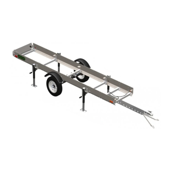
Off-road sawmill trailer
Hide thumbs
Also See for Woodlander:
- Operator's manual (52 pages) ,
- Operator's manual (72 pages) ,
- Operator's manual (48 pages)
Table of Contents
Advertisement
Quick Links
Advertisement
Table of Contents

Related Manuals for Woodland Mills Woodlander


Summary of Contents for Woodland Mills Woodlander
- Page 1 WOODLANDER OFF-ROAD ™ SAWMILL TRAILER *Track Not Included OPERATOR’S MANUAL The Woodlander ™ and Woodlander ™ MAX are off-road only sawmill trailers compatible with HM126, HM130 & HM130MAX sawmills. Woodlander ™ is a trademark of Woodland Mills, Inc.
- Page 2 This page intentionally left blank.
-
Page 3: Table Of Contents
2018-2023 Woodlander ™ (MAX) Operator’s Manual TABLE OF CONTENTS TABLE OF CONTENTS __________________________________________________1 INTRODUCTION ________________________________________________________3 GENERAL SAFETY RULES_______________________________________________4 INSPECTION/MAINTENANCE _____________________________________________5 TECHNICAL SPECIFICATIONS ____________________________________________6 BOLT TORQUE SPECIFICATIONS _______________________________________6 UNPACKING ___________________________________________________________7 COMPONENT LISTS ____________________________________________________8 TO-SCALE HARDWARE ______________________________________________10 BOLTS & SCREWS ___________________________________________________10 SCALES _____________________________________________________________12... - Page 4 2018-2023 Woodlander ™ (MAX) Operator’s Manual OPERATION __________________________________________________________49 LOCKING-DOWN THE SAWMILL HEAD _________________________________49 REPLACEMENT PARTS ORDERING ______________________________________51 EXPLODED ASSEMBLY VIEWS __________________________________________52 CHASSIS AND TRACK _______________________________________________52 TONGUE __________________________________________________________53 NORTH AMERICA _________________________________________________53 EUROPE __________________________________________________________53 AXLES, WHEELS, AND FENDERS ______________________________________54 LIGHTING _________________________________________________________55 NORTH AMERICA _________________________________________________55...
-
Page 5: Introduction
The entire manual must be read and understood before using the trailer. If any questions should arise that are not covered by this manual, please contact Woodland Mills, Inc. ... -
Page 6: General Safety Rules
2018-2023 Woodlander ™ (MAX) Operator’s Manual GENERAL SAFETY RULES WARNING! Read and understand all instructions. Failure to follow all instructions listed below may result serious injury. WARNING! The warnings, cautions, and instructions discussed in this instruction manual cannot cover all possible conditions or situations that could occur. -
Page 7: Inspection/Maintenance
2018-2023 Woodlander ™ (MAX) Operator’s Manual INSPECTION/MAINTENANCE • Check the tires before all trips. Make sure they are inflated to the pressure shown on the tire. • Grease the axle bearings every 3 months or 1000 miles [1600 km], whichever comes first. -
Page 8: Technical Specifications
Fenders Removable Safety Locking pins and safety straps to secure sawhead while travelling Woodlander: 640 lb [290 kg] Shipping Weight Woodlander MAX: 655 lb [297 kg] Woodlander: 556 lb [252 kg] Product Weight Woodlander MAX: 571 lb [259 kg] BOLT TORQUE SPECIFICATIONS... -
Page 9: Unpacking
2018-2023 Woodlander ™ (MAX) Operator’s Manual UNPACKING Remove all the parts from the steel crate. Set the crate aside as it will be used as a support for several of the assembly steps. 0001675-M-EN: Rev C Page 07-Oct-2022... -
Page 10: Component Lists
2018-2023 Woodlander ™ (MAX) Operator’s Manual COMPONENT LISTS Verify all component and hardware quantities are correct prior to assembling the trailer. End Gusset Jack Mount [0001373] [0001376] Joining Gusset Swivel Jack [0001374] [0006798] Swivel Jack Long Side Plate Handle [0001363]... - Page 11 (North America) (Europe) [0001676-1] [0001391] Front Reflector Nameplate (Europe) [0001886] [0001392] Lock-Down Plate [0001990] STD = Woodlander (Standard) MAX = Woodlander MAX Lock-Down Pin [0001394] Components in are specific to European trailers Linch Pin [0004720] 0001675-M-EN: Rev C Page 07-Oct-2022...
-
Page 12: To-Scale Hardware
2018-2023 Woodlander ™ (MAX) Operator’s Manual TO-SCALE HARDWARE BOLTS & SCREWS Hardware graphics are printed at 1:1 scale for ease of identification. Simply place the hardware over the image in the tables to verify it is the correct size. HHB-MBE075FCJ... - Page 13 2018-2023 Woodlander ™ (MAX) Operator’s Manual HHB-MBR155PCM** M12 X 1.75 X 100 mm HEX BOLT FHH-MBJ075FCJ M8 X 1 X 20 mm FLANGED HEX BOLT FHH-MBJ080FCJ M8 X 1 X 25 mm FLANGED HEX BOLT 116x FHH-MBM085FCM M10 X 1.5 X 30 mm FLANGED HEX BOLT FHH-MBM090PCM M10 X 1.5 X 35 mm FLANGED HEX BOLT...
-
Page 14: Scales
2018-2023 Woodlander ™ (MAX) Operator’s Manual FHH-MBR090PCM M12 X 1.75 X 35 mm FLANGED HEX BOLT PPH-MBA075FCE*** M5 X 0.8 X 20 mm PHILLIPS PAN HEAD SCREW * M12 X 1.75 X 70 mm Hex Bolts not applicable on European trailers ** M12 X 1.75 X 100 mm Hex Bolts not applicable on North American trailers... -
Page 15: Nuts
2018-2023 Woodlander ™ (MAX) Operator’s Manual NUTS 0006202 HLN-MBECH M12 X 1.5 LUG NUT M6 X 1 LOCK NUT HLN-MBMCL HLN-MBRCL M10 X 1.5 LOCK NUT M12 X 1.75 LOCK NUT FLN-MBACH FLN-MBJCH M5 X 0.8 FLANGED LOCK NUT* M8 x 1 FLANGED LOCK NUT... -
Page 16: Sawmill Components
2018-2023 Woodlander ™ (MAX) Operator’s Manual SAWMILL COMPONENTS These components from the sawmill are required to build the trailer. They do not ship with the Woodlander ™ trailer. Track Rail Centre Bunk [0001073] [0001084] Reinforcement Mid Bunk Plate [0001080] [0001072]... -
Page 17: Trailer Assembly
2018-2023 Woodlander ™ (MAX) Operator’s Manual TRAILER ASSEMBLY 1. TOOLS REQUIRED Tool Specification Phillips Head Screwdriver No. 3 Wrench/Socket 8 mm Wrench/Socket 9 mm Wrench/Socket 10 mm Wrench/Socket 13 mm Wrench/Socket 14 mm Wrench/Socket 15 mm Wrench/Socket 18 mm Adjustable Wrench... -
Page 18: Gussets
2018-2023 Woodlander ™ (MAX) Operator’s Manual 2. GUSSETS Using the hardware listed below, assemble the gussets to the track as shown on the next page. Ensure the track width is set correctly (see track widths on next page), and measure diagonally to check for squareness. - Page 19 2018-2023 Woodlander ™ (MAX) Operator’s Manual End Bunk M10 x 30 mm Mid Bunk M10 Lock Nut M10 x 30 mm Centre Bunk End Gusset M10 Lock Nut M10 x 30 mm Mid Bunk Joining Gusset M10 x 40 mm...
-
Page 20: Side Plates
2018-2023 Woodlander ™ (MAX) Operator’s Manual 3. SIDE PLATES Using the shipping crate as an assembly aid, lay two (2) 2X4s across the top the crate near each end. Position the track/gusset assembly on the 2X4s, ensuring it is centred end-to-end. - Page 21 2018-2023 Woodlander ™ (MAX) Operator’s Manual Using the hardware listed below, hang the side plates using the M10 X 30 mm and M10 X 35 mm bolts. Do not tighten these bolts. The eight (8) M10 X 35 mm bolts are used with the carriage stops.
- Page 22 2018-2023 Woodlander ™ (MAX) Operator’s Manual M10 X 35 mm at Carriage Stops M10 X 30 mm M10 X 30 mm at all other at all other locations locations 0001675-M-EN: Rev C Page 07-Oct-2022...
-
Page 23: Front And Rear Cross Beams
2018-2023 Woodlander ™ (MAX) Operator’s Manual 4. FRONT AND REAR CROSS BEAMS Using the hardware listed below, install the front and rear cross beams (2 front, 1 rear). Ensure the cross beam with the two holes is assembled at the front. Do not tighten these bolts. - Page 24 2018-2023 Woodlander ™ (MAX) Operator’s Manual Front Cross Beam Cross Beam Front Cross Beam Rear 0001675-M-EN: Rev C Page 07-Oct-2022...
-
Page 25: Side Plate-To-Rail Offset & Bolt Torquing
2018-2023 Woodlander ™ (MAX) Operator’s Manual 5. SIDE PLATE-TO-RAIL OFFSET & BOLT TORQUING Use the components listed below to assist with correcting any side plate-to-rail offsets and gaps. Ratchet Strap Swivel Jack Swivel Jack [2x] Handle Before torquing the chassis bolts as shown on the following 3 pages, verify there is a ⅜-½ in [10-13 mm] offset between the top of the track rails and the top of the side plates. - Page 26 2018-2023 Woodlander ™ (MAX) Operator’s Manual Ensuring the side plate-to-rail offset is uniform, tighten and torque only the four (4) highlighted bolts securing the long side plate. Do this for both sides of the trailer. With the long side plate secured in place, note the gaps (if any) between the short side plates and the long side plates.
- Page 27 2018-2023 Woodlander ™ (MAX) Operator’s Manual Attach the ratchet strap hooks to the rectangular openings in the short side plates and pull the sides plates together to help eliminate any gaps. Keep the strap in place until all the bolts are torqued as outlined on the next page.
- Page 28 2018-2023 Woodlander ™ (MAX) Operator’s Manual While maintaining a uniform side plate-to-rail offset, torque the remaining bolts per the table in section, BOLT TORQUE SPECIFICATIONS, starting from the centre and working towards the outer ends. Ensure the track is straight, level, and square during this procedure.
-
Page 29: Inner Cross Beams And Jack Mounts
2018-2023 Woodlander ™ (MAX) Operator’s Manual 6. INNER CROSS BEAMS AND JACK MOUNTS Using the hardware listed below, install the 2 remaining cross beams and 4 jack mounts. Torque all the bolts per the table in section BOLT TORQUE SPECIFICATIONS. - Page 30 2018-2023 Woodlander ™ (MAX) Operator’s Manual 0001675-M-EN: Rev C Page 07-Oct-2022...
- Page 31 2018-2023 Woodlander ™ (MAX) Operator’s Manual Next, lower the trailer until the cross beams are resting on the crate. Slide the swivel jacks onto the jack mounts and secure them with the locking pins. Raise the jacks up to slide the crate out from under the trailer assembly. Place blocks of wood underneath each jack if necessary to achieve the required clearance.
-
Page 32: Axle Mounts And Axle Cross Beam
2018-2023 Woodlander ™ (MAX) Operator’s Manual 7. AXLE MOUNTS AND AXLE CROSS BEAM Using the hardware listed below, install the axle mount cross beam and left/right axle mounts with fender adapter as shown. Tighten these bolts. M10 X 35 mm... - Page 33 2018-2023 Woodlander ™ (MAX) Operator’s Manual Front Rear Ensure sleeves are oriented towards the rear of the trailer Thread knob into Axle Mount prior to bolting to side plate 0001675-M-EN: Rev C Page 07-Oct-2022...
-
Page 34: Axles
2018-2023 Woodlander ™ (MAX) Operator’s Manual 8. AXLES Using the hardware listed below, install the axles as shown on the next page. Do not torque these bolts until instructed in step, WHEELS. M12 X 35 mm Flanged Hex Axle [Left]... - Page 35 2018-2023 Woodlander ™ (MAX) Operator’s Manual Install up to 3 shim plates Front per axle if necessary to level axles. Only use if axles require levelling. Axle swingarms point towards rear of trailer. Rear 0001675-M-EN: Rev C Page 07-Oct-2022...
-
Page 36: Tongue And Coupler
2018-2023 Woodlander ™ (MAX) Operator’s Manual 9. TONGUE AND COUPLER Using the hardware listed below, install the trailer tongue and hitch coupler. Don’t tighten the M10 X 160 mm bolts in this step since the plug for the lights will be routed through the tongue in the following step. - Page 37 2018-2023 Woodlander ™ (MAX) Operator’s Manual Europe M12 X 100 mm North America M12 X 70 mm M10 X 160 mm Side plate removed for clarity. 0001675-M-EN: Rev C Page 07-Oct-2022...
-
Page 38: Lighting
2018-2023 Woodlander ™ (MAX) Operator’s Manual 10. LIGHTING Using the hardware listed below, install the taillight bracket and country appropriate wire harness. Secure tail lights to the taillight bracket using M5 flanged lock nuts before mounting taillight bracket to trailer. Use cable clamps to secure wire harness to side plates down right- side of trailer. - Page 39 2018-2023 Woodlander ™ (MAX) Operator’s Manual M5 X 20 mm Pan Head M5 Lock Nut (Included with wiring harness) M5 Lock Nut M8 X 25 mm M5 X 20 mm Europe Only Pan Head **Note: Tail lights (North America and Europe) and side lights (North America only) are integral to the wire harness.
- Page 40 2018-2023 Woodlander ™ (MAX) Operator’s Manual Europe Only M5 Lock Nut Route wire harness through tongue prior to tightening M10 X 160 mm bolts M5 X 20 mm Pan Head M6 X 20 mm There are 2 cable clamps per short side plate (2) and 4 per long side plate (1) for a total of 8.
-
Page 41: Nameplates
2018-2023 Woodlander ™ (MAX) Operator’s Manual 11. NAMEPLATES Using the hardware listed below, install the two (2) Woodlander nameplates as shown. M6 X 20 mm Woodlander Hex Bolt Nameplate M6 Flat Washer M6 Lock Nut 0001675-M-EN: Rev C Page 07-Oct-2022... - Page 42 2018-2023 Woodlander ™ (MAX) Operator’s Manual 0001675-M-EN: Rev C Page 07-Oct-2022...
-
Page 43: Head Lock-Down Plates
2018-2023 Woodlander ™ (MAX) Operator’s Manual 12. HEAD LOCK-DOWN PLATES Place the assembled sawhead on the trailer. Using the hardware listed below, install the head lock down plates as shown on the next page. M6 X 40 mm Hex Bolt... - Page 44 2018-2023 Woodlander ™ (MAX) Operator’s Manual Remove the eight (8) spacers from the carriage wheel axles and discard the four (4) short spacers. Only the four (4) tall spacers will be reused in the next steps. Discard short spacers Using the provided M6 X 40 mm and M6 X 25 mm bolts, install the lock-down plates in place of the short spacers with the taller spacer sandwiched between.
- Page 45 2018-2023 Woodlander ™ (MAX) Operator’s Manual Drill four (4) holes for the lock-down plates using the provided 10 mm [⅜ in] drill bit. Measure 64-½ in [164 cm] from the rear edge of the track rail (not the carriage stop) to the rear post of the sawhead.
-
Page 46: Wheels
2018-2023 Woodlander ™ (MAX) Operator’s Manual 13. WHEELS Using the hardware listed below, install the tires on the axles. Using a torque wrench, torque the lug nuts to 80 ft•lb / 110 N•m following the pattern shown below. 1/2-20 Lug Nut 5.30-12 Wheel... -
Page 47: Wheel Alignment Adjustment
2018-2023 Woodlander ™ (MAX) Operator’s Manual WHEEL ALIGNMENT ADJUSTMENT With the wheels installed, observe their alignment to each other. If the wheels point inward (pigeon-toed) or outward (duck-footed), the axle position needs to be adjusted before the trailer can be towed behind a vehicle. One or both wheels may be affected. -
Page 48: Fenders
2018-2023 Woodlander ™ (MAX) Operator’s Manual 14. FENDERS Using the hardware listed below, assemble the fenders to the fender brackets. Tighten these bolts. Slide the post on the fender bracket into the sleeve on the axle mount and insert the locking pin through the hole located at the bottom of the fender bracket post. - Page 49 2018-2023 Woodlander ™ (MAX) Operator’s Manual Some components removed for clarity 0001675-M-EN: Rev C Page 07-Oct-2022...
-
Page 50: Safety Chain
2018-2023 Woodlander ™ (MAX) Operator’s Manual 15. SAFETY CHAIN Using the hardware below, install the safety chain on the trailer tongue. M10 X 40 mm Safety Chain Hex Bolt M10 Flat Washer M10 Lock Nut 0001675-M-EN: Rev C Page 07-Oct-2022... -
Page 51: Operation
2018-2023 Woodlander ™ (MAX) Operator’s Manual OPERATION LOCKING-DOWN THE SAWMILL HEAD When transporting the trailer, it is imperative that the sawmill head is locked-down securely to the trailer. Start by inserting the four (4) locking pins through the lock-down brackets and secure them with linch pins. - Page 52 2018-2023 Woodlander ™ (MAX) Operator’s Manual Lower the sawhead to its lowest position. Then insert the short strap hook into the cross beam lifting eye on one side of the sawmill, route the long strap down and under the bottom of the trailer, then up to the opposite lifting eye.
-
Page 53: Replacement Parts Ordering
Record the part number (e.g. 0001071, HHB-MBM080FCJ, etc.) in the “Part No.” column. Contact Woodland Mills through the website or via phone/email. If possible, include the invoice or sales number from the purchased product so an associated account can be located. If the account has multiple addresses on file, please indicate to which address the replacement... -
Page 54: Exploded Assembly Views
2018-2023 Woodlander ™ (MAX) Operator’s Manual EXPLODED ASSEMBLY VIEWS CHASSIS AND TRACK 0001675-M-EN: Rev C Page 07-Oct-2022... -
Page 55: Tongue
2018-2023 Woodlander ™ (MAX) Operator’s Manual TONGUE NORTH AMERICA EUROPE 0001675-M-EN: Rev C Page 07-Oct-2022... -
Page 56: Axles, Wheels, And Fenders
2018-2023 Woodlander ™ (MAX) Operator’s Manual AXLES, WHEELS, AND FENDERS 0001675-M-EN: Rev C Page 07-Oct-2022... -
Page 57: Lighting
2018-2023 Woodlander ™ (MAX) Operator’s Manual LIGHTING NORTH AMERICA 0001675-M-EN: Rev C Page 07-Oct-2022... -
Page 58: Europe
2018-2023 Woodlander ™ (MAX) Operator’s Manual EUROPE 0001675-M-EN: Rev C Page 07-Oct-2022... -
Page 59: Nameplates
2018-2023 Woodlander ™ (MAX) Operator’s Manual NAMEPLATES 0001675-M-EN: Rev C Page 07-Oct-2022... -
Page 60: Swivel Jacks
2018-2023 Woodlander ™ (MAX) Operator’s Manual SWIVEL JACKS 0001675-M-EN: Rev C Page 07-Oct-2022... -
Page 61: Head Lock-Down
2018-2023 Woodlander ™ (MAX) Operator’s Manual HEAD LOCK-DOWN 0001675-M-EN: Rev C Page 07-Oct-2022... -
Page 62: Parts Lists
0001369 CROSS BEAM 0002900 CROSS BEAM, WOODLANDER MAX 0001370 CROSS BEAM, FRONT 0002899 CROSS BEAM, FRONT, WOODLANDER MAX 0001376 JACK MOUNT 0006798 SWIVEL JACK, PIPE MOUNT, SIDEWIND HANDLE 0006800 CRANK HANDLE SOCKET DRIVE, ¾ in [19 mm], SWIVEL JACK 0001679... - Page 63 2018-2023 Woodlander ™ (MAX) Operator’s Manual Quantity Item Part No. Description HM126 HM130 HM130 0005146 RATCHET STRAP, 50 mm WD, 4500 mm LG 5.30-12 WHEEL, 5.30-12 L44649 ROLLER BEARING, TAPERED, 1-1/16 in SFT, 1-3/64 in HSG, .56 in WD HHB-MBE075FCJ HEX HEAD BOLT, CLS 8.8, M6 X 1, 20 mm LG, FULL...
-
Page 64: Europe
0001369 CROSS BEAM 0002900 CROSS BEAM, WOODLANDER MAX 0001370 CROSS BEAM, FRONT 0002899 CROSS BEAM, FRONT, WOODLANDER MAX 0001376 JACK MOUNT 0006798 SWIVEL JACK, PIPE MOUNT, SIDEWIND HANDLE 0006800 CRANK HANDLE SOCKET DRIVE, ¾ in [19 mm], SWIVEL JACK 0001679... - Page 65 2018-2023 Woodlander ™ (MAX) Operator’s Manual Quantity Item Part No. Description HM126 HM130 HM130 0001394 LOCK-DOWN PIN 0004720 LINCH PIN, 4.5 mm DIA, 25 mm USEABLE LG, 32 mm LG 0004742 DRILL BIT, 10 mm, JOBBERS LG 0005146 RATCHET STRAP, 50 mm WD, 4500 mm LG 5.30-12...
-
Page 66: Notes
2018-2023 Woodlander ™ (MAX) Operator’s Manual NOTES 0001675-M-EN: Rev C Page 07-Oct-2022... - Page 67 This page intentionally left blank.
Need help?
Do you have a question about the Woodlander and is the answer not in the manual?
Questions and answers