Table of Contents
Advertisement
Quick Links
Advertisement
Table of Contents

Related Manuals for Woodland Mills FP160


Summary of Contents for Woodland Mills FP160
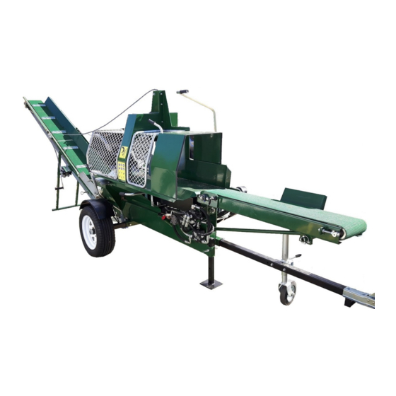
- Page 1 WOODLAND FIREWOOD PROCESSOR FP160 2014-2020 Owner’s Manual...
- Page 2 Sørg for visuell justering av båndet så godt som det lar seg gjøre før start og utfør finjusteringen så snart motoren har startet. Lykke til! Kundeservice – Norge Heggenveien 8, NO-3370 Vikersund Woodland Mills Europa Org.nr.: 922 635 706 e-post aderesse: post@woodland-mills.no...
-
Page 3: Table Of Contents
Table of Contents 2018 model uppgrade ........3 Introduction……….…………………………………4 Product………………………………………………5 Safety……………………………..…………………6 Assembly……………………………………………8 Preparations…………………..…………………..20 Operating…………………….…..………………..20 Maintenance………………………………………20 Chainsaw bar……………………….…………….20 Spare parts………………………………………..20 Exploded view with parts number......21... -
Page 4: Introduction
Introduction Congratulations on your purchase and welcome to Woodland Mills. This manual gives you the necessary information about your machine so you will be able to use it properly. The entire manual must be read and understood before you start using the machine. If any questions should arise that are not covered by this manual, please contact our customer service at 1-855-476-6455. -
Page 5: Product
This ensures high safety, lower noise and longer life of both chain and bar. Technical Specifications SPECIFICATIONS FP160 Max splitting force 12 ton Max log diameter 15”... -
Page 6: Safety
Safety The machine may only be used in the manner prescribed in this manual. Deviations may lead to health and safety requirements not being met. The user is responsible to read through the instructions and follow them properly. WARNING! Never tamper with the machine’s functionality or construction. It may lead to a deterioration of safety! WARNING! Never leave the machine unattended during operation! - Page 7 WARNING! Check before each use that the auto splitter stops when the protective cage is opened! If this feature does not work, the machine must not be used! WARNING! Never use a defective machine! Be careful when cutting and splitting the log! Emergency stop The machine is equipped with an emergency stop which stops the whole machine.
-
Page 8: Assembly
Assembly 1. Remove processor and all parts from the steel shipping crate. 2. Insert axle through the processor ensuring it is centred and tighten the bolts to hold it securely in place. Note, it is important to ensure the two holes are facing up as they are used to hold the wheel fenders in place. - Page 9 4. Install the fenders and attach to the axle using the two bolts as shown below. 5. The four lug nuts of each wheel should be torque to 90 ft-lbs. 6. Match hydraulic line ‘B’ up with fitting ‘B’ and tighten with a wrench. Do the same for ‘F’ to ‘F’. ...
- Page 10 7. Install the chainsaw bar guard using the 3 bolts in the areas shown below. Do not fully tighten the bolts yet. This will be done in a further step. 8. Remove the adhesive backing from the chainsaw bar guard and position the bar oil tank in place.
- Page 11 10. Install the chainsaw bar pull handle using the 2 bolts shown below. 11. Install the piston between the chainsaw bar handle and the back plate as shown below. Do not over tighten the bolt at the handle as is needs to be loose to enable it to rotate smoothly.
- Page 12 12. Uninstall the “L” shaped bracket, flip it over, and re-install it as shown below. A smooth transition motion is recommended. There are slots in both directions allowing positional adjustability to achieve proper actuation of valve. When the chainsaw bar handle is in the “up” position, the valve will be closed and the actuator rod will be at an angle.
- Page 13 15. Install the notched plate on the processor with the 2 nuts and bolts provided. This plate is used to lock the handle in place which holds the 2/4 way splitter is at the desired height. 16. Install the 2/4 way splitter bottom support as shown below. The handle can also be installed at this point along with the 2/4 way splitter itself.
- Page 14 17. Install log deck roller assembly as shown in below images. 18. The chain can now be adjusted to ensure the tension is set correctly. Proper chain tension is achieved when the chain can be pulled away from the bar by hand 1/8” - 1/4”. To tighten or loosen the chain, the two bolts can be loosened using a 13mm wrench.
- Page 15 20. With the galvanized bracket now bolted to the conveyor, lift it in place so that it can be attached to the processor. A scissor jack or car jack can be used to aid in lifting the conveyor up into place so the mounting holes align. Washer Washer Washer...
- Page 16 22. The top half can now be latched to the bottom half as shown below. Once latched in place, one person can begin to lift the conveyor up so another person can slide the support leg in place and latch the chain. Latch Support ...
- Page 17 24. The hydraulic line should be connected to the conveyor motor using connections ‘C’ to ‘C’ and ‘D’ to ‘D’, Use a wrench to tighten. 25. Install the winch on the winch bracket as shown below. 26. Remove the pulley on the operator side of the conveyor, feed the cable through and re- install the pulley. ...
- Page 18 27. Remove the large pulley from the pulley housing on top of the chain guard, feed the cable through and re-install the pulley. 28. Attach the hook to the hook attachment point on the conveyor. 29. Insert the square black tongue into the processor and tighten the two bolts to lock it in place.
- Page 19 30. Attach tongue jack as pictured below. There are two bolts that hold it securely to the tongue. The leg stand can be used when the processor is in operation. Tongue Jack Leg Stand With the processor now assembled, the engine oil, hydraulic oil and bar oil can be added into the appropriate tanks.
-
Page 20: Preparations
Preparations Place the machine on a at and stable surface. Check all oil levels and ll up if necessary. Check that the machine does not have any defects. Remember to use proper protective equipment. Operating Adjusting the log length The log length stop is adjusted with bolts. Unscrew these, move the allocation to the desired position and tighten the screws to adjust the log length. - Page 22 WOODLAND MILLS 1-855-476-6455 www.woodlandmills.ca www.woodlandmills.eu www.woodlandsawmills.com Woodland Mills | 171 North Port Rd., Unit 1 Port Perry Ontario, Canada. L9L 1B2 | Phone 855-476-6455 | Email general@woodlandmills.ca Page...
Need help?
Do you have a question about the FP160 and is the answer not in the manual?
Questions and answers