Table of Contents
Advertisement
Quick Links
Advertisement
Table of Contents

Related Manuals for Datalogic Matrix 400


Summary of Contents for Datalogic Matrix 400
- Page 1 MATRIX 400™ Reference Manual...
-
Page 2: All Rights Reserved
Datalogic Automation S.r.l. Via S. Vitalino 13 40012 - Lippo di Calderara di Reno Bologna - Italy Matrix 400™ Reference Manual Ed.: 12/2008 ALL RIGHTS RESERVED Datalogic reserves the right to make modifications and improvements without prior notification. Datalogic shall not be liable for technical or editorial errors or omissions contained herein, nor for incidental or consequential damages resulting from the use of this material. -
Page 3: Table Of Contents
Accessories ...31 Application Examples ...32 External Lighting Systems ...35 INSTALLATION ...39 Package Contents ...39 Mechanical Dimensions... 40 Mounting and Positioning Matrix 400™ ... 42 CBX ELECTRICAL CONNECTIONS...44 Power Supply...45 Main Serial Interface...45 4.2.1 RS232 Interface...46 4.2.2 RS485 Full-Duplex Interface...47 4.2.3 RS485 Half-Duplex Interface ... 48... - Page 4 ID-NET™ Interface ...69 5.5.1 ID-NET™ Cables ...69 5.5.2 ID-NET™ Response Time ... 70 5.5.3 ID-NET™ Network Termination ... 74 Auxiliary RS232 Interface ...74 Ethernet Interface (Matrix 400 XXX-010 models only) ... 75 Inputs ... 76 Outputs ...79 5.10 User Interface ...81 TYPICAL LAYOUTS ...82...
- Page 5 8.4.6 Region Of Interest Windowing ... 117 8.4.7 Direct Part Marking Applications... 118 Image Capture and Decoding... 120 Statistics ...120 MAINTENANCE ...121 Cleaning...121 TROUBLESHOOTING ...122 10.1 General Guidelines ...122 TECHNICAL FEATURES... 125 GLOSSARY...127 INDEX...130...
-
Page 6: References
"Reader" refers to the Matrix 400™ reader. "You" refers to the System Administrator or Technical Support person using this manual to install, configure, operate, maintain or troubleshoot a Matrix 400™ reader. REFERENCE DOCUMENTATION For further details refer to: the VisiSet™ Help On Line, Matrix Reading Methods, Matrix Host Mode Programming, Matrix SW Parameter Guide, Matrix Code Quality Verifier Solution provided as supplementary documentation on CD-ROM. -
Page 7: Compliance
COMPLIANCE For installation, use and maintenance it is not necessary to open the reader. EMC COMPLIANCE In order to meet the EMC requirements: connect reader chassis to the plant earth ground by means of a flat copper braid shorter than 100 mm;... -
Page 8: Handling
HANDLING The Matrix 400™ is designed to be used in an industrial environment and is built to withstand vibration and shock when correctly installed, however it is also a precision product and therefore before and during installation it must be handled correctly to avoid damage. - Page 9 do not weld the reader into position which can cause electrostatic, heat or reading window damage. do not spray paint near the reader which can cause reading window damage.
-
Page 10: General View
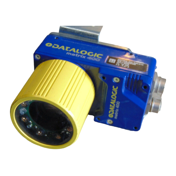
Device Class Label Mounting Holes (12) Lens Cover Lens (separate accessory) Internal Illuminator (separate accessory) Matrix 400™ Figure A HMI X-PRESS™ Interface "POWER ON" LED Power - Serial Interfaces - I/O Connector Ethernet Connector Ethernet Connection LED (Ethernet Models Only) -
Page 11: Rapid Configuration
CAUTION 1. In a dust-free environment, remove the Matrix 400™ Lens Cover by unscrewing it. Do not touch the sensor aperture, lens glass or lens cover glass. These areas must be kept clean. Avoid any abrasive substances that might damage these surfaces during cleaning. -
Page 12: Required Accessories
When One Shot or Phase Mode Operating mode is used, the reader is activated by an External Trigger (photoelectric sensor) when the object enters its reading zone. PG 6000 CAB-MS01 Matrix 400™ Figure 2 – Matrix 400™ in Stand Alone Layout Internal Illuminators 93A401020 93A401022 93A401020... - Page 13 CBX100/CBX500 Pinout for Matrix 400™ The table below gives the pinout of the CBX100/CBX500 terminal block connectors. Use this pinout when the Matrix 400™ reader is connected by means of the CBX100/CBX500: CBX100/500 Terminal Block Connectors Input Power Power Supply Input Voltage +...
-
Page 14: Main Interface
19-pin Connector Pinout for Matrix 400™ The table below gives the pinout of the 19-pin M16 male connector for connection to the power supply and input/output signals. Use this pinout when the Matrix 400™ reader is connected by means of the 19-pin connector:... -
Page 15: Step 3 - Mount And Position The Reader
STEP 3 – MOUNT AND POSITION THE READER 1. To mount the Matrix 400™, use the mounting brackets to obtain the most suitable position for the reader. Two of the most common mounting configurations are shown in the figures below. Other mounting solutions are provided in par. 3.3. -
Page 16: Step 4 - Focus The Reader
STEP 4 – FOCUS THE READER Matrix 400™ provides a built-in tool called Blue Diamonds™ to aid focusing the reader. The Blue Diamonds™ are accessed through the X-PRESS™ Interface. 1. Remove the lens cover in order to focus the reader. -
Page 17: Step 5 - Calibrate Image Density
7. Replace the lens cover, screwing it tightly to the base. STEP 5 – CALIBRATE IMAGE DENSITY In order to function correctly to the fullest extent of its capabilities, Matrix 400™ must acquire information regarding image density or PPI (pixels per inch). This calibration takes place through the X-PRESS™... - Page 18 5 (five) seconds Matrix 400™ will exit without saving the parameters to memory, the Setup LED will not remain on continuously but it will just stop blinking. In this case Matrix 400™ emits a long low pitched beep. 7. Exit the Setup function by pressing the X-PRESS™...
-
Page 19: Step 6 - X-Press™ Configuration
STEP 6 – X-PRESS™ CONFIGURATION Once Matrix 400™ has calibrated image density, you can configure it for optimal code reading relative to your application. This configuration can be performed either through the X- PRESS™ Interface or the VisiSet™ configuration program. - Page 20 In this case Matrix 400™ emits a long low pitched beep. 10. Exit the Setup function by pressing the X- PRESS™ push button once. If you have used this procedure to configure Matrix 400™ go to step 9. green green parameters...
-
Page 21: Step 7 - Installing Visiset™ Configuration Program
STEP 7 – INSTALLING VISISET™ CONFIGURATION PROGRAM ™ VisiSet is a Datalogic reader configuration tool providing several important advantages: Setup Wizard for rapid configuration and new users; Defined configuration directly stored in the reader; Communication protocol independent from the physical interface allowing to consider the reader as a remote object to be configured and monitored. -
Page 22: Step 8 - Configuration Using Setup Wizard
MATRIX 400™ REFERENCE MANUAL Set the communication parameters from the "Options" menu. Then select "Connect", the following window appears: Figure 16 - VisiSet™ Main Window After Connection STEP 8 – CONFIGURATION USING SETUP WIZARD The Setup Wizard option is advised for rapid configuration or for new users. It allows reader configuration in a few easy steps. - Page 23 2. Remove the lens cover in order to focus the reader and loosen the two Locking Knobs on the lens. Adjust the Focus ring to the "Far position" and the Diaphragm ring to the "F4" setting which is the preferred setting for installation. Place the Grade A Barcode Test Chart in front of the reader at the correct reading distance (see step 3 and the Optical Accessory Selection table in the par.
- Page 24 4. Select a Calibration Mode choice and press the "Calibrate" button. The reader flashes once acquiring the image and auto determines the best exposure and gain settings. If the code symbology is enabled by default, the code will also be decoded. 5.
- Page 25 RAPID CONFIGURATION Continue rotating the Focusing ring on the lens a little farther; the Current Focus Quality Bar decreases (red) see below. Rotate the Focusing ring in the opposite direction. The Current Focus Quality Bar (green) increases towards the vertical optimal focus line (green) until the optimal focus is reached;...
- Page 26 Using the Grade A Barcode Test Chart, this step performs image density calibration in order for Matrix 400™ to function correctly and to the fullest extent of its capabilities. The Setup Result section of the Setup Wizard window shows the code type results and the image density calibration settings.
- Page 27 8. Select a Saving Options choice and press the "Save" button. 9. Close the Setup Wizard. If your application has been configured using the VisiSet™ Setup Wizard, your reader is ready. If necessary you can use VisiSet™ for advanced reader configuration.
-
Page 28: Step 9 - Test Mode
STEP 9 – TEST MODE Use a code suitable to your application to test the reading performance of the system. 1. Enter the Test function by pressing and holding the X-PRESS™ push button until the Test LED is on. 2. Release the button to enter the Test function. Once entered, the Bar Graph on the five LEDs is activated and if the reader starts reading codes the Bar-Graph shows the Good Read Rate. -
Page 29: Advanced Reader Configuration
Reference Manual. Code Quality Verification Matrix 400™ can be used as a Code Quality Verifier according to the ISO/IEC 15415, ISO/IEC 15416, AS9132, and AIM DPM Standards. For more details see the Matrix 400™ Code Quality Verifier Solution manual on the CD-ROM. -
Page 30: Introduction
2 INTRODUCTION 2.1 PRODUCT DESCRIPTION Matrix 400™ is a Datalogic industrial compact 2D imager designed and produced to be a high performance affordable solution for both linear and two-dimensional code reading applications. Matrix 400™ uses imaging technology and provides complete reading system functions by integrating image capturing, decoding and communicating in a single compact and versatile product. - Page 31 INTRODUCTION Standard Application Program A Standard Application Program is factory-loaded onto Matrix 400™. This program controls code reading, data formatting, serial port and Ethernet interfacing, and many other operating and control parameters. It is completely user configurable from a Laptop or PC using the dedicated configuration software program VisiSet™, provided on CD-ROM with the reader.
- Page 32 Ease of Setup Quick installation without PC by using X-PRESS™ interface for easy and intuitive setup Blue Diamonds™ aiming and focusing system Automatic Imager calibration and Code Settings Calibration Tool to verify exact code positioning in the Field of View and to maximize the reading performance ...
- Page 33 482 g. Electrical connection of Power, Host interfaces and I/O signals is provided through an M16 (IP67) 19-pin connector (Figure A, 9). A standard M12 D-Coded (IP67) Ethernet connector is present on Matrix 400 XXX-X1X models (Figure A, 10).
-
Page 34: Indicators And Keypad Button
2.2 INDICATORS AND KEYPAD BUTTON The following LED indicators are located on the reader: yellow LED indicates connection to the on-board Ethernet network (for Ethernet models) (Figure 19, 1) blue LED indicates that the reader is connected to the power supply (Figure 19, 2) In normal operating mode the colors and meaning of the five LEDs are illustrated in the following table: green LED indicates that the reader is ready to operate (Figure 19, 3) -
Page 35: Id-Net
INTRODUCTION 2.3 ID-NET™ The ID-NET™ network is a built-in high-speed interface dedicated for high-speed reader interconnection. ID-NET™ is in addition to the Main and Auxiliary serial interfaces. The following network configurations are available: ID-NET™ M/S Synchronized: Single station – multiple readers ID-NET™... -
Page 36: How To Setup/Configure The Reader Network
ID-NET™ M/S Multidata: Multiple stations – single reader ID-NET™ interface allows connection of readers reading objects placed on independent conveyors. All readers are typically located far away from each other and they use a dedicated presence sensor. At the end of each reading phase, each reader transmits its own data message to the host. Thanks to ID-NET™, data collection among readers is accomplished at a high speed without the need of an external multiplexing device. - Page 37 7. Configure the other device parameters via VisiSet™ [Operating Mode, Calibration, Data Collection parameters, etc.]. 8. If using the CBX connection box equipped with a BM100 Backup module, perform Device Backup at the Slave. The Slave device is now Configured. Repeat these steps for each Slave reader in the ID- NET™...
-
Page 38: X-Press™ Human Machine Interface
2.4 X-PRESS™ HUMAN MACHINE INTERFACE X-PRESS™ is the intuitive Human Machine Interface designed to improve ease of installation and maintenance. Status information is clearly presented by means of the five colored LEDs, whereas the single push button gives immediate access to the following relevant functions: ... - Page 39 READY green LEARN GOOD green SETUP TRIGGER yellow FOCUS yellow TEST STATUS Release button to enter Setup Mode Test Mode (Function 1) Once entered, the Bar Graph on the five LEDs is activated and if the imager starts reading codes the Bar-Graph shows the Good Read Rate. In case of a NO READ condition, only the Status LED is on and blinks.
-
Page 40: Model Description
Setup LED will remain on continuously and Matrix 400™ emits 3 high pitched beeps. If the calibration cannot be reached after a timeout of about 5 (five) seconds Matrix 400™ will exit without saving the parameters to memory, the Setup LED will not remain on continuously but it will just stop blinking. -
Page 41: Accessories
2.6 ACCESSORIES The following accessories can be used with the Matrix 400™ reader. Accessory Description Lenses LNS-1006 6 mm C-Mount Lens LNS-1109 9 mm C-Mount Lens LNS-1112 12.5 mm C-Mount Lens LNS-1116 16 mm C-Mount Lens LNS-1125 25 mm C-Mount Lens... -
Page 42: Application Examples
(see Figure 20). Figure 20 - Address Coded in Datamatrix Symbology for Automated Mail Processing The Matrix 400™ high resolution image sensors allow the reading of many small codes in a single image (see 96 vial application in Figure 21). - Page 43 Figure 22 - Unidose Flow-Pack with PDF417 Code Figure 23 - Overprinted Barcode Readable by Matrix 400™ also Through the Envelope Window Film Figure 24 - Barcode Printed on Curved Surface Readable by Matrix 400™ in spite of Image Optical Distortion Matrix 400™...
- Page 44 MATRIX 400™ REFERENCE MANUAL Figure 26 - Dot Peening Marking on Metal Surface with Multi-dot per Code Element Figure 27 - Directly Marked Dot Matrix Code Characterized by Outstanding Separation Distance between Adjacent Code Elements Figure 28 - DataMatrix Code Directly Marked on PCB Surface by Using Laser Etching Technology...
-
Page 45: External Lighting Systems
2.8 EXTERNAL LIGHTING SYSTEMS In some direct part marking applications best reading results are obtained by using an external lighting system. A series of accessory illuminators are available which cover a variety of applications. The LT-100 Cone Lighting System provides a circular symmetrical light source designed for the following applications: ... - Page 46 The LT-210 Mini Spot Lighting System provides a high intensity light source designed for the following applications: with uneven, noisy and scratched surfaces where dot peening or laser etching codes are directly marked onto metal surfaces or PCBs and need to be highlighted. Here the use of more than one Spot Light can remove any shadowing effect.
- Page 47 INTRODUCTION The LT-316 60° Dark Field Ring Lighting System is designed for reading codes produced by Dot Peening (especially by a 120° stylus) or Laser Etching on flat, reflective parts. Figure 35 - LT-316 60° Dark Field Ring Lighting System The LT-410 Coaxial Lighting System is an axial diffuse illuminator designed for reading codes produced by Dot Peening or Laser Etching on flat parts having a matte, specular or mixed surface reflectivity.
- Page 48 MATRIX 400™ REFERENCE MANUAL The LT-511 Dome Lighting System is a diffuse dome light designed for reading printed label or Direct Marking codes on parts with a curved surface. Figure 38 - LT-511 Dome Lighting System The LT-630 Four Bar Lighting System is designed for Code verification applications according to ISO/IEC 15415 or ISO/IEC 15416 specifications.
-
Page 49: Installation
3 INSTALLATION 3.1 PACKAGE CONTENTS Verify that the Matrix 400™ reader and all the parts supplied with the equipment are present and intact when opening the packaging; the list of parts includes: Matrix 400™ reader Quick Reference Guide Test Charts (2) ... -
Page 50: Mechanical Dimensions
3.2 MECHANICAL DIMENSIONS Matrix 400™ can be installed to operate in different positions. The twelve screw holes (M4 x 5) on the body of the reader are for mechanical fixture (Figure 41). The diagram below gives the overall dimensions of the reader and may be used for its installation. - Page 51 [2.40] [1.97] 12.5 [0.49] [0.17] [0.28] [0.17] [1.57] Figure 42 - Mounting Bracket Overall Dimensions 12.5 [0.49] [0.17] [0.16] N°7 [in] [0.12]...
-
Page 52: Mounting And Positioning Matrix 400
MATRIX 400™ REFERENCE MANUAL 3.3 MOUNTING AND POSITIONING MATRIX 400™ Using the Matrix 400™ mounting brackets you can obtain rotation on the various axes of the reader as shown in the diagram below: Pitch Tilt Figure 43 –Positioning with Mounting Bracket (Back) - Page 53 Assure at least 10° Minimize Figure 46 - Pitch angle Figure 47 - Skew angle The Tilt angle is represented by the value T in Figure 48. Matrix 400™ can read labels with any tilt angle. Minimize Figure 48 - Tilt angle...
-
Page 54: Cbx Electrical Connections
CAB-MSxx accessory cables. These accessory cables terminate in a 19-pin connector on the Matrix 400™ side and in a 25-pin male D-sub connector on the CBX side. We recommend making system connections through one of the CBX connection boxes since they offer the advantages of easy connection, easy device replacement and filtered reference signals. -
Page 55: Power Supply
To avoid electromagnetic interference when the reader is connected to a CBX connection box, verify the jumper positions in the CBX as indicated in its Installation Manual. NOTE 4.1 POWER SUPPLY Power can be supplied to the reader through the CBX100/500 spring clamp terminal pins as shown in Figure 49: Power Supply The power must be between 10 and 30 Vdc only. -
Page 56: Rs232 Interface
The RTS and CTS signals control data transmission and synchronize the connected devices. TRANSMISSION TX DATA IDLE If the RTS/CTS handshaking protocol is enabled, the Matrix 400™ activates the RTS output to indicate a message is to be transmitted. The receiving unit activates the CTS input to enable the transmission. Function... -
Page 57: Rs485 Full-Duplex Interface
4.2.2 RS485 Full-Duplex Interface The RS485 full-duplex (5 wires + shield) interface is used for non-polled communication protocols in point-to-point connections over longer distances (max 1200 m / 3940 ft) than those acceptable for RS232 communications or in electrically noisy environments. The CBX pinout follows: CBX100/500 SGND... -
Page 58: Rs485 Half-Duplex Interface
In a Multiplexer layout, the Multidrop address must also be set via serial channel by the VisiSet™ utility or by the Host Programming Mode. Figure 55 shows a multidrop configuration with Matrix 400™ readers connected to a Multiplexer. This is an example of multidrop wiring. Consult the multiplexer manual for complete wiring instructions. - Page 59 CBX ELECTRICAL CONNECTIONS Figure 55 - Matrix 400™ Multidrop Connection to a Multiplexer...
-
Page 60: Id-Net™ Interface
4.3 ID-NET™ INTERFACE CBX100/500 Shield 4.3.1 ID-NET™ Cables The following instructions are referred to Figure 57, Figure 58 and Figure 59. The general cable type specifications are: CAT5 twisted pair + additional CAT5 twisted pair, shielded cable AWG 24 (or AWG 22) stranded flexible. We recommend using DeviceNet cables (drop or trunk type) to the following reference standards: AN50325 –... -
Page 61: Id-Net™ Response Time
4.3.2 ID-NET™ Response Time The following figure shows the response time of the ID-NET™ network. This time is defined as the period between the Trigger activation and the beginning of data transmission to the Host. CONDITIONS: ID-NET™ M/S Synchronized layout ... - Page 62 MATRIX 400™ REFERENCE MANUAL Figure 57 – ID-NET™ Network Connections with isolated power blocks...
- Page 63 CBX ELECTRICAL CONNECTIONS Figure 58 - ID-NET™ Network Connections with Common Power Branch Network...
- Page 64 MATRIX 400™ REFERENCE MANUAL Figure 59 – ID-NET™ Network Connections with Common Power Star Network...
-
Page 65: Id-Net™ Network Termination
4.3.3 ID-NET™ Network Termination The network must be properly terminated in the first and last reader of the network. This is done by setting the ID-NET™ Termination Resistance Switch in the CBX100/500 to ON. 4.4 AUXILIARY RS232 INTERFACE The RS232 auxiliary interface is available for Point-to-Point, Pass Through or Master/Slave connections. -
Page 66: Inputs
4.5 INPUTS There are two optocoupled polarity insensitive inputs available on the reader: Input 1 (External Trigger) and Input 2, a generic input: The External Trigger can be used in One Shot Mode or in Phase Mode. Its main functions are: ... -
Page 67: External Trigger Input Connections Using External Power
Power is available directly to the Input Device, independently from the Power Supply Switch inside the CBX. CAUTION Figure 62 – PH-1 External Trigger Using MATRIX 400™ Power Figure 63 - NPN External Trigger Using MATRIX 400™ Power EXTERNAL TRIGGER INPUT CONNECTIONS USING EXTERNAL POWER... -
Page 68: Input 2 Connections Using External Power
CBX100/500 INPUT 2 CONNECTIONS USING MATRIX 400™ POWER Power is available directly to the Input Device, independently from the Power Supply Switch inside the CBX. CAUTION INPUT 2 CONNECTIONS USING EXTERNAL POWER Figure 66 - PNP Input 2 Using External Power... -
Page 69: Outputs
Figure 67 - NPN Input 2 Using External Power 4.6 OUTPUTS Two optocoupled general purpose outputs are available. The meaning of the two outputs Output 1 and Output 2 can be defined by the user. They are typically used either to signal the data collection result or to control an external lighting system. - Page 70 Power Supply Switch inside the CBX. CAUTION Output Device Power to Output device Figure 68 - Open Emitter Output Using MATRIX 400™ Power Output Device Power to Output device Figure 69 - Open Collector Output Using MATRIX 400™ Power OUTPUT CONNECTIONS USING EXTERNAL POWER...
-
Page 71: External Lighting Systems
4.7 EXTERNAL LIGHTING SYSTEMS If an External Illuminator is used, it can be powered from the CBX connection box. It must be connected to the Vdc and GND terminal clamps. Power is available directly to the Illuminator, independently from the Power Supply Switch inside the CBX. -
Page 72: User Interface - Host
4.8 USER INTERFACE - HOST The following table contains the pinout for standard RS232 PC Host interface. For other user interface types please refer to their own manual. 9-pin male connector RS232 PC-side connections 25-pin male connector Name Name... -
Page 73: Matrix 400™ Connector Electrical Connections
5 MATRIX 400™ CONNECTOR ELECTRICAL CONNECTIONS 5.1 M16 19-PIN CONNECTOR The Matrix 400™ reader is equipped with an M16 19-pin male connector (Binder, 423 Series) for connection to the power supply, serial interfaces and input/output signals. The details of the connector pins are indicated in the following table:... -
Page 74: M12-D 4-Pin Connector (Ethernet)
5.2 M12-D 4-PIN CONNECTOR (ETHERNET) In Matrix 400 xxx-x1x models, an M12 D-Coded connector is provided for the on-board Ethernet connection. This interface is IEEE 802.3 10 BaseT and IEEE 802.3u 100 BaseTx compliant. See par. 5.7 for connection details. -
Page 75: Rs232 Interface
The RTS and CTS signals control data transmission and synchronize the connected devices. If the RTS/CTS handshaking protocol is enabled, Matrix 400™ activates the RTS output to indicate a message is to be transmitted. The receiving unit activates the CTS input to enable the transmission. -
Page 76: Rs485 Full-Duplex Interface
5.4.2 RS485 Full-Duplex Interface The RS485 full-duplex (5 wires + shield) interface is used for non-polled communication protocols in point-to-point connections over longer distances (max 1200 m / 3940 ft) than those acceptable for RS232 communications or in electrically noisy environments. The following pins of the M16 19-pin connector are used for RS485 full-duplex communication: Name... -
Page 77: Rs485 Half-Duplex Interface
5.4.3 RS485 Half-Duplex Interface This interface is provided for backward compatibility. We recommend using the more efficient ID-NET™ network for Master/Slave or Multiplexer layouts. NOTE The RS485 half-duplex (3 wires + shield) interface is available for polled communication protocols. It can be used for Multidrop connections with a Datalogic Multiplexer, (see par. 6.5) exploiting a proprietary protocol based on polled mode called MUX32 protocol, where a master device polls slave devices to collect data. - Page 78 The figure below shows a multidrop configuration with Matrix 400™ readers connected to a Multiplexer. This is an example of multidrop wiring. Consult the multiplexer manual for complete wiring instructions. CAUTION Figure 81 - Matrix 400™ Multidrop Connection to a Mutiplexer...
-
Page 79: Id-Net™ Interface
5.5 ID-NET™ INTERFACE Name 5.5.1 ID-NET™ Cables The following instructions are referred to Figure 83, Figure 84 and Figure 85. The general cable type specifications are: CAT5 twisted pair + additional CAT5 twisted pair, shielded cable AWG 24 (or AWG 22) stranded flexible. We recommend using DeviceNet cables (drop or trunk type) to the following reference standards: AN50325 –... -
Page 80: Id-Net™ Response Time
5.5.2 ID-NET™ Response Time The following figure shows the response time of the ID-NET™ network. This time is defined as the period between the Trigger activation and the beginning of data transmission to the Host. CONDITIONS: ID-NET™ M/S Synchronized layout ... - Page 81 19-PIN CONNECTOR ELECTRICAL CONNECTIONS Figure 83 – ID-NET™ Network Connections with isolated power blocks...
- Page 82 MATRIX 400™ REFERENCE MANUAL Figure 84 - ID-NET™ Network Connections with Common Power Branch Network...
- Page 83 19-PIN CONNECTOR ELECTRICAL CONNECTIONS Figure 85 – ID-NET™ Network Connections with Common Power Star Network...
-
Page 84: Id-Net™ Network Termination
5.5.3 ID-NET™ Network Termination The network must be properly terminated by a 120 Ohm resistor at the first and last reader of the network. 5.6 AUXILIARY RS232 INTERFACE The RS232 auxiliary interface is available for Point-to-Point, Pass Through or Master/Slave connections. -
Page 85: Ethernet Interface (Matrix 400 Xxx-010 Models Only)
The following is an example of a connection to a LAN using a CAB-ETH-M0x straight through cable: D-coded For direct connection to a PC use the CAB-ETH-M0x cable with a crossover adapter. On the Matrix 400™ Ethernet interface the following communication channels are available: Data Socket ... -
Page 86: Inputs
5.8 INPUTS There are two optocoupled polarity insensitive inputs available on the M16 19-pin connector of the reader: Input 1 (External Trigger) and Input 2, a generic input: The External Trigger can be used in One Shot Mode or in Phase Mode. Its main functions are: ... -
Page 87: External Trigger
Figure 88 - External Trigger Using PNP PH-1 Photocell EXTERNAL TRIGGER INPUT CONNECTIONS USING MATRIX 400™ POWER Matrix 400™ Figure 89 – External Trigger PNP Using Matrix 400™ Power Matrix 400™ Figure 90 - External Trigger NPN Using Matrix 400™ Power EXTERNAL TRIGGER INPUT CONNECTIONS USING EXTERNAL POWER Matrix 400™... -
Page 88: Input Device
Figure 92 - External Trigger NPN Using External Power Name INPUT 2 CONNECTIONS USING MATRIX 400™ POWER Matrix 400™ Figure 93 - Input PNP Using Matrix 400™ Power Matrix 400™ Figure 94 - Input NPN Using Matrix 400™ Power Vext 30 Vdc max. -
Page 89: Outputs
INPUT 2 CONNECTIONS USING EXTERNAL POWER Matrix 400™ Figure 95 - Input PNP Using External Power Matrix 400™ Figure 96 - Input NPN Using External Power 5.9 OUTPUTS Two opto-coupled general purpose outputs are available on the M16 19-pin connector. The meaning of the two outputs Output 1 and Output 2 can be defined by the user. - Page 90 MATRIX 400™ REFERENCE MANUAL The output signals are fully programmable being determined by the configured Activation/Deactivation events, Deactivation Timeout or a combination of the two. Refer to the Digital I/O folder in the VisiSet™ Help On Line for further details.
-
Page 91: User Interface
PC RS232 COM port connections. M16 19-pin female Matrix 400™ Trigger RS232 PC-side connections 25-pin male connector B I1A Figure 99- Test Cable for Matrix 400™ Name 9-pin D-sub female Power Supply Power GND VS (10 – 30 VDC) -
Page 92: Typical Layouts
When One Shot or Phase Mode operating mode is used, the reader can be activated by an External Trigger (for example a pulse from a photoelectric sensor) when the object enters its reading zone. PG6000 CAB-MSxx Matrix 400™ Figure 100 – Serial Interface Point-to-Point Layout Terminal Main Serial Interface (RS232 or RS485 Full-Duplex) ... - Page 93 When One Shot or Phase Mode operating mode is used, the reader can be activated by an External Trigger (photoelectric sensor) when the object enters its reading zone. Power Matrix 400™ Host Figure 101 – Fieldbus Interface Point-to-Point Layout CBX500 ...
-
Page 94: Pass-Through
6.2 PASS-THROUGH Pass-through mode allows two or more devices to be connected to a single external serial interface. Each reader transmits the messages received by the Auxiliary interface onto the Main interface. All messages will be passed through this chain to the host. When One Shot or Phase Mode operating mode is used, the reader can be activated by an External Trigger (for example a pulse from a photoelectric sensor) when the object enters its reading zone. - Page 95 (Master and Slaves) to accept input on the Auxiliary interface, for example to connect a device such as a hand-held reader for manual code reading capability. Each Matrix 400™ transmits its own messages plus any messages received by its Auxiliary interface onto the ID-NET™ interface. The Master passes all messages to the Host.
-
Page 96: Id-Net
6.3 ID-NET™ The ID-NET™ connection is used to collect data from several readers to build a multi-point or a multi-sided reading system; there can be one master and up to 31 slaves connected together. The slave readers are connected together using the ID-NET™ interface. Every slave reader must have an ID-NET™... - Page 97 For a Master/Slave Multidata layout each reader has its own reading phase independent from the others; each single message is sent from the master reader to the Host computer. Master Power Host The auxiliary serial interface of the slave readers can be used in Local Echo communication mode to control any single reader (visualize collected data) or to configure it using the VisiSet™...
- Page 98 Alternatively, the Master reader can communicate to the Host as a Slave node on a Fieldbus network. This requires using an accessory Fieldbus interface board installed inside the CBX500 connection box. System configuration can be accomplished through the Auxiliary interface of each individual reader (internal CBX500 9-pin connector) using the VisiSet™...
-
Page 99: Rs232 Master/Slave
6.4 RS232 MASTER/SLAVE This interface is provided for backward compatibility. We recommend using the more efficient ID-NET™ network for Master/Slave or Multiplexer layouts. NOTE The RS232 master/slave connection is used to collect data from several readers to build either a multi-point or a multi-sided reading system; there can be one master and up to 9 slaves connected together. -
Page 100: Multiplexer
6.5 MULTIPLEXER This interface is provided for backward compatibility. We recommend using the more efficient ID-NET™ network for Master/Slave or Multiplexer layouts. NOTE Each reader is connected to a Multiplexer (for example MX4000) with the RS485 half-duplex main interface through a CBX connection box. Before proceeding with the connection it is necessary to select the MUX32 communication protocol and the multidrop address for each reader. -
Page 101: Ethernet Connection (Matrix 400 Xxx-010 Models Only)
6.6 ETHERNET CONNECTION (MATRIX 400 XXX-010 MODELS ONLY) For Matrix 400 XXX-010 models, the Ethernet connection is possible in two different layouts. In both layouts, before proceeding with the connection, it is necessary to configure the reader Ethernet parameters via VisiSet™. For further details, see the Ethernet Folder in the VisiSet™... - Page 102 When using a Local Area Network (LAN), one or more Matrix 400 XXX-010s can be connected to the network by using CAB-ETH-M0x straight through cables: Ethernet Interface (Straight Through Cables) Auxiliary Serial Interface (Local Echo) (RS232) External Trigger (for One Shot or Phase Mode) Matrix 400™...
-
Page 103: Reading Features
Referring to Figure 112 and the formula below, use the data in the following table to calculate the FOV for your application. Model Lens LNS-1109 9 mm LNS-1112 12.5 mm Matrix 400 LNS-1116 16 mm 400-0x0 LNS-1125 25 mm (SXGA) LNS-1135 35 mm... -
Page 104: Horizontal Fov Vs. Reading Distance Diagrams
Example: The FOV for a Matrix 400 600-0x0 base using the 16 mm lens at a focus distance of 200 mm is: = 2 [(200 mm + 35 mm) tan (24°/2)] = 100 mm = 2 [(200 mm + 35 mm) tan (18°/2)] = 74 mm 7.2 HORIZONTAL FOV VS. -
Page 105: Linear) Codes
7.2.2 1D (Linear) Codes 1D Codes – Matrix 400 400-0x0 (SXGA) 0.30 0.25 0.20 0.15 0.15 0.12 0.12 0.10 1D Codes – Matrix 400 400-0x0 (SXGA) 0.30 0.25 0.20 0.15 0.15 0.10 0.10 1D Codes – Matrix 400 600-0x0 (UXGA) 9 mm, 12.5 mm, 16 mm... - Page 106 0.25 0.20 0.15 0.15 0.12 0.12 0.12 0.10 0.10 0.10 1D Codes – Matrix 400 600-0x0 (UXGA) 0.25 0.20 0.15 0.15 0.12 0.12 0.10 0.10 0.10 9 mm, 12.5 mm, 16 mm 0.50 0.38 0.38 0.33 0.33 0.30 0.30 0.30 0.25...
-
Page 107: Bi-Dimensional) Codes
7.2.3 2D (Bi-dimensional) Codes 2D Codes – Matrix 400 400-0x0 (SXGA) 0.33 2D Codes – Matrix 400 400-0x0 (SXGA) 0.33 0.30 0.25 0.20 0.15 9 mm, 12.5 mm, 16 mm 0.50 0.38 0.38 0.33 0.33 0.30 0.30 0.25 0.25 0.20 0.20... - Page 108 2D Codes – Matrix 400 600-0x0 (UXGA) 0.30 0.25 0.20 0.20 0.15 0.15 0.12 2D Codes – Matrix 400 600-0x0 (UXGA) 0.30 0.25 0.20 0.15 0.15 0.12 0.12 0.10 9 mm, 12.5 mm, 16 mm 0.50 0.38 0.38 0.33 0.33 0.30...
-
Page 109: Maximum Line Speed And Exposure Time Calculations
The essential condition to avoid blurring effects between two adjacent elements in a dynamic reading application is: The maximum (theoretical) line speed LS can be calculated as follows: Example: A Matrix 400™ 600-010 using: Internal Lighting Mode = Very High Power Strobe Exposure Time (x10 Code Resolution (X) = 0.254 mm (10 mils) -
Page 110: Line Speed
and LS are represented in the graph below as the curved line for X (code exp (max) (max) resolution). Values above the curve result in blurring. In practice, the application values are somewhere below the theoretical line, (in the green area), due to environmental and other conditions. - Page 111 READING FEATURES SW Limit exp (min) SW/HW Limit Line Speed Readable Blurring is the minimum Exposure Time value obtainable for the specific application. It can exp (min) be evaluated in static reading conditions and depends on the Matrix reader model selected for the application (internal lighting system, optical lens, diaphragm aperture, reading distance) and on any external lighting system.
-
Page 112: Software Configuration
8 SOFTWARE CONFIGURATION Software configuration of your Matrix 400™ for static reading or simple code reading applications can be accomplished by the Rapid Configuration procedure using the X- PRESS™ HMI (which requires no external configuration program) or by using the VisiSet™... -
Page 113: Startup
After completing the mechanical and electrical connections to Matrix 400™, you can begin software configuration as follows: 1. Power on the Matrix 400™ reader. Wait for the reader startup. The system bootstrap requires a few seconds to be completed. The reader automatically enters Run Mode. -
Page 114: Visiset™ Options
8.3.1 VisiSet™ Options The Options item from the VisiSet™ menu (see Figure 113) presents a window allowing you to configure: the logging function (Log) VisiSet™ window properties (Environment) VisiSet™ communication channel (Communication) Figure 114 - Options - Log Figure 115 - Options - Environment... - Page 115 SOFTWARE CONFIGURATION Figure 116 - Options – Communication: Serial Port Figure 117 - Options – Communication: Ethernet...
-
Page 116: Configuration
8.4 CONFIGURATION Once connected to Matrix 400™ as described in par. 8.3, you can modify the configuration parameters as follows: 1. Press the Calibration Tool button from the Main Menu. Matrix 400™ will download its permanent memory configuration parameters with the default values (if it is the first time) to VisiSet™. -
Page 117: Edit Reader Parameters
SOFTWARE CONFIGURATION 8.4.1 Edit Reader Parameters The Parameter Setup window displays the configuration parameters grouped in a series of folders. Each parameter can be modified by selecting a different item from the prescribed list in the box, or by typing new values directly into the parameter box. By right clicking the mouse when positioned over the name of a specific Parameter or Group, a pop-up menu appears allowing you to directly manage that particular parameter or group. - Page 118 Parameters to verify/modify: Operating Mode Calibration Communication Ethernet Fieldbus Display Diagnostics Reading System Layout Image Processing 1D & 2D, Postal Codes Data Collection Digital I/O Match Code ...
-
Page 119: Send Configuration Options
SOFTWARE CONFIGURATION When all the configuration parameters are set correctly, save them to the Matrix 400™ reader by pressing the Send button. See Figure 118. For successive configuration of other readers or for backup/archive copies, it is possible to save the configuration onto your PC by selecting the Save Configuration File option from the File menu. - Page 120 Environmental Parameters regard the device Identity and Position in a Network (ID-NET™, Master/Slave RS232, MUX 32, Ethernet) and are not influenced by the "Send Default Configuration" and "Send Configuration" commands. This allows individual devices to be configured differently without affecting their recognized position in the network. The following is a list of the Environmental Parameters: READING SYSTEM LAYOUT - Device Network Setting...
- Page 121 SOFTWARE CONFIGURATION For device replacement it is necessary to send the previously saved configuration (both Configuration and Environmental parameters) to the new device. To do this select "Send Configuration with Options" from the Device Menu and check the Environmental Parameters checkbox: In order to return a device to its absolute default parameters including Environmental parameters, the following Send Default Configuration with Options"...
-
Page 122: Calibration
By selecting the Calibration Tool from the VisiSet™ Main Menu (F), the following window appears together with the Parameter Setup window: This tool provides a "real-time" image display while Matrix 400™ is reading. It also gives immediate results on the performance of the installed Matrix 400™ reader. - Page 123 The following examples show some of the typical conditions occurring during the installation: Under-exposure: To correct this result it is recommended to change the following parameters in their order of appearance: 1. increase the Exposure Time 2. increase the Gain In general, a longer exposure time corresponds to a lighter image but is susceptible to blurring due to code movement.
- Page 124 MATRIX 400™ REFERENCE MANUAL Over-exposure: To correct this result it is recommended to change the following parameters in their order of appearance: 1. decrease the Gain 2. decrease the Exposure Time Figure 121 - Example Over Exposure: Too Light...
- Page 125 Moving code out of the Field of View: To correct this result and have the code completely visible in F.O.V., it is possible to follow one or both the procedures listed below: reposition the reader use the Acquisition Trigger Delay by tuning the Delay Time (x100µs) Figure 122 - Example out of FOV...
-
Page 126: Multi Image Acquisition Settings
From Readable Not Readable For more details see the Matrix 400™ Help On-Line. Self Tuning Image Processing In the Image Processing parameter setup menu, the Self Tuning parameters manage the Image Processing and Symbology related parameters. They perform different processing... -
Page 127: Region Of Interest Windowing
The Top, Bottom, Left and Right parameters allow to precisely define the image window to be processed, visualized and saved. In Matrix 400™ 600-0x0 models the frame rate is dependent on the number of lines (or rows) in the defined window. -
Page 128: Direct Part Marking Applications
MATRIX 400™ REFERENCE MANUAL 8.4.7 Direct Part Marking Applications Decoding Method: Direct Marking For DataMatrix and QR code the Decoding Method parameter selects the decoding algorithm according to the printing/marking technique used to create the symbol and on the overall printing/marking quality. The Direct Marking selection improves the decode rate for low quality Direct Part Mark codes and in general for Direct Part Mark codes with dot peening type module shapes. - Page 129 Image Filter Sets the filter to be applied to the image before being processed. This parameter can be used to successfully decode particular ink-spread printed codes (ex. direct part mark codes). A different filter can be applied to each Image Acquisition Setting. The Erode Filter enlarges the image dark zones to increase readability.
-
Page 130: Image Capture And Decoding
MATRIX 400™ REFERENCE MANUAL 8.5 IMAGE CAPTURE AND DECODING By using the Capture Image and Decode Last Image functions from the VisiSet™ Main menu, you can get information about the image decodable codes in terms of Symbology, encoded Data, Position and Orientation, Decode Time and Code Quality Assessment Metrics. -
Page 131: Maintenance
MAINTENANCE 9 MAINTENANCE 9.1 CLEANING Clean the reading window (see Figure A, 1) periodically for continued correct operation of the reader. Dust, dirt, etc. on the window may alter the reading performance. Repeat the operation frequently in particularly dirty environments. Use soft material and alcohol to clean the window and avoid any abrasive substances. -
Page 132: Troubleshooting
When wiring the device, pay careful attention to the signal name (acronym) on the CBX100/500 spring clamp connectors (chp. 4). If you are connecting directly to the Matrix 400™ M16 19-pin connector pay attention to the pin number of the signals (chp. 5). ... - Page 133 Problem One Shot or Phase Mode using serial trigger source: the ”TRIGGER” LED is not blinking. Phase Mode: ”TRIGGER" correctly blinking but no image displayed VisiSet™ Calibration Tool window. Continuous Mode: the ”TRIGGER” LED is not blinking. Any Operating Mode: ”TRIGGER”...
- Page 134 Problem are incorrect, corrupted or incomplete. How do I obtain my reader Serial Number? How do I obtain my reader Order Number? TROUBLESHOOTING GUIDE Suggestion In VisiSet Communication folder check the settings of Header and Terminator String parameters. In VisiSet™...
-
Page 135: Technical Features
11 TECHNICAL FEATURES ELECTRICAL FEATURES Power Supply Voltage Power Consumption Communication Interfaces Main - RS232 - RS485 full-duplex - RS485 half-duplex Auxiliary - RS232 ID-NET™ Ethernet (Ethernet Models only) Inputs Input 1 (External Trigger) and Input 2 Max. Voltage Max. Input Current Outputs Output 1 and Output 2 = 0 mA) Max. -
Page 136: Software Features
SOFTWARE FEATURES Readable Code Symbologies 1-D and stacked PDF417 Standard and Micro PDF417 Code 128 (EAN 128) Code 39 (Standard and Full ASCII) Interleaved 2 of 5 Codabar Code 93 Pharmacode EAN-8/13 - UPC-A/E (including Addon 2 and Addon 5) ... -
Page 137: Glossary
GLOSSARY (Association for Automatic Identification and Mobility): AIM Global is the international trade association representing automatic identification and mobility technology solution providers. AIM DPM Quality Guideline Standard applicable to the symbol quality assessment of direct part marking (DPM) performed in using two-dimensional bar code symbols. It defines modifications to the measurement and grading of several symbol quality parameters. - Page 138 Depth of Field The difference between the minimum and the maximum distance of the object in the field of view that appears to be in focus. Diffused Illumination Distributed soft lighting from a wide variety of angles used to eliminate shadows and direct reflection effects from highly reflective surfaces.
- Page 139 (International Organization for Standardization): A network of the national standards institutes of several countries producing world-wide industrial and commercial standards. LED (Light Emitting Diode) A low power electronic light source commonly used as an indicator light. It uses less power than an incandescent light bulb but more than a Liquid Crystal Display (LCD).
-
Page 140: Index
M12-D 4-Pin Connector (Ethernet), 64 M16 19-Pin Connector, 63 Main Serial Interface, 45, 64 Maintenance, 121 Mechanical Dimensions, 40 Model Description, 30 Mounting and Positioning Matrix 400™, 42 Multiplexer, 90 Optical Accessory Selection, 93 Outputs, 59, 79 Package Contents, 39 Pass-Through, 84... -
Page 141: Declaration Of Conformity
dichiara che declares that the déclare que le bescheinigt, daß das Gerät declare que el Matrix 4XX YYY-ZZZ sono conformi alle Direttive del Consiglio Europeo sottoelencate: are in conformity with the requirements of the European Council Directives listed below: sont conformes aux spécifications des Directives de l'Union Européenne ci-dessous: der nachstehend angeführten Direktiven des Europäischen Rats: cumple con los requisitos de las Directivas del Consejo Europeo, según la lista siguiente: 89/336/EEC EMC Directive... - Page 142 www.automation.datalogic.com...
Need help?
Do you have a question about the Matrix 400 and is the answer not in the manual?
Questions and answers