Table of Contents
Advertisement
Quick Links
Advertisement
Table of Contents

Related Manuals for Datalogic Matrix 210N


Summary of Contents for Datalogic Matrix 210N
- Page 1 > Matrix 210N™...
- Page 2 Matrix 210N™ Reference Manual Ed.: 11/2016 © 2015 - 2016 Datalogic S.p.A. and its Group companies ALL RIGHTS RESERVED. Protected to the fullest extent under U.S. and international laws. Copying or altering of this document is prohibited without express written consent from Datalogic S.p.A.
-
Page 3: Table Of Contents
CONTENTS REFERENCES ......................vi Conventions ......................... vi Reference Documentation ................... vi Support Through The Website ..................vi Patents ......................... vi COMPLIANCE ......................vii EMC Compliance ......................vii Power Supply ....................... vii CE Compliance ......................vii FCC Compliance ......................vii EAC Compliance ......................viii Laser Safety ........................ - Page 4 Mechanical Dimensions ....................52 Mounting and Positioning Matrix 210N ............... 55 CBX ELECTRICAL CONNECTIONS ................. 58 Power Supply ......................59 Main Serial Interface ....................59 4.2.1 RS232 Interface ......................60 4.2.2 RS422 Full-Duplex Interface ..................61 ID-NET Interface ......................62 4.3.1 ID-NET Cables ......................
- Page 5 7.6.2 Restore Default Environment ..................131 7.6.3 Restore Factory Defaults ..................132 Diagnostic Alarms ..................... 132 Statistics ........................133 BM150 Display Module Configuration and Messages ..........134 7.9.1 Configuration Through DL.CODE ................134 7.9.2 Accessing the HMI Interface Through Keypad and Display Menu ......134 7.9.3 Display Messages .....................
-
Page 6: References
Reading Methods, provided as supplementary documentation on the DL.CODE mini-DVD (downloaded .zip file or mini-DVD accessory). SUPPORT THROUGH THE WEBSITE Datalogic provides several services as well as technical support through its website. Log on to www.datalogic.com and click on the Industrial Automation links for further information: ... -
Page 7: Compliance
European directive. Since the directives and applicable standards are subject to continuous updates, and since Datalogic promptly adopts these updates, therefore the EU declaration of conformity is a living document. The EU declaration of conformity is available for competent authorities and customers through Datalogic commercial reference contacts. -
Page 8: Eac Compliance
The CU Conformity certification has been achieved; this allows the Product to bear the Eurasian mark of conformity. LASER SAFETY The Matrix 210N liquid lens models contain two aiming Laser LEDs used to position the reader. This product conforms to the applicable requirements of IEC 60825-1 and complies with 21 CFR 1040.10 except for deviations pursuant to Laser Notice N°... -
Page 9: Handling
HANDLING The Matrix 210N is designed to be used in an industrial environment and is built to withstand vibration and shock when correctly installed, however it is also a precision product and therefore before and during installation it must be handled correctly to avoid damage. - Page 10 do not weld the reader into position which can cause electrostatic, heat or reading window damage. do not spray paint near the reader which can cause reading window damage.
-
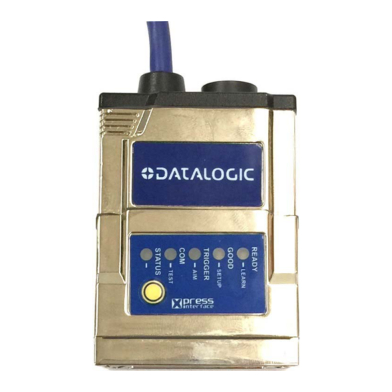
Page 11: General View
GENERAL VIEW Matrix 210N™ Software Adjustable Focus (Liquid Lens) Models Figure A Device Class and Warning Labels Power - Serial - I/O Cable Connector Internal Illuminator Mounting Holes (4) Power On LED Good Read LED Spot (green) Ethernet Connection LED... - Page 12 Matrix 210N™ Fixed Focus Models Figure A Device Labels Power - Serial - I/O Cable Connector Lens Mounting Holes (4) Power On LED Internal Illuminator Ethernet Connection LED HMI X-PRESS Interface Good Read LED Spot (green) Ethernet Connector Aiming System (Blue Ring)
-
Page 13: Rapid Configuration
To connect the system in an Ethernet point-to-point configuration, you need the hardware indicated in Figure 1. In this layout the data is transmitted to the Host from the Matrix 210N on-board Ethernet interface by using a CAB-ETH-M0x cable. There is no need to use a crossover adapter since Matrix 210N incorporates an autocross function. - Page 14 MATRIX 210N™ REFERENCE MANUAL USB Connections Matrix 210N USB models can be connected in a Point-to-Point layout to a local host through their USB cable. No external power supply is necessary. Figure 2 – Matrix 210N USB Point-to-Point Layout...
- Page 15 To connect the system in a Serial point-to-point configuration, you need the hardware indicated in Figure 3. In this layout the data is transmitted to the Host from the Matrix 210N main serial interface. Matrix 210N power and I/O device connections take place through the CBX connection box.
- Page 16 MATRIX 210N™ REFERENCE MANUAL CBX100/CBX500 Pinout for Matrix 210N The table below gives the pinout of the CBX100/CBX500 terminal block connectors. Use this pinout when the Matrix 210N reader is connected by means of the CBX100/CBX500: CBX100/500 Terminal Block Connectors Input Power...
-
Page 17: Step 2 - Mount And Position The Reader
RAPID CONFIGURATION STEP 2 – MOUNT AND POSITION THE READER 1. To mount the Matrix 210N, use the mounting brackets to obtain the most suitable position for the reader. The most common mounting configuration is shown in the figure below. -
Page 18: Step 3 - X-Press Configuration For Software Adjustable Focus Models
Aim LED will stop blinking and Matrix 210N emits 3 high pitched beeps. If the Autofocus cannot be reached after a timeout of about 3 (three) minutes Matrix 210N will exit without saving the parameters to memory, the Aim LED will stop blinking and in this case Matrix 210N emits a long low pitched beep. - Page 19 RAPID CONFIGURATION Once Matrix 210N is focused at the correct reading distance, you must configure it for optimal code reading relative to your application. 5. Repeat the Aim function, but now position a single code from your application at the center of the FOV (equidistant from the laser pointers).
- Page 20 X-PRESS push button once. After a short delay the procedure is cancelled. NOTE: If you have used this procedure to configure Matrix 210N go to step The Learn procedure will not recognize the following symbologies: Postal Codes, Pharmacode, MSI, Standard 2 of 5,...
-
Page 21: Step 4 - X-Press Configuration For Fixed Focus Models
FOR FIXED FOCUS MODELS NOTE: For Software Adjustable Focus models go to Step 3. Matrix 210N™ fixed focus models provide a built-in aiming system to aid reader positioning. The aiming system is accessed through the X-PRESS Interface. 1. Power the reader on. During the reader startup (reset or restart phase), all the LEDs blink for one second. - Page 22 MATRIX 210N™ REFERENCE MANUAL Once Matrix 210N is focused at the correct reading distance, you must configure it for optimal code reading relative to your application. Setup 5. Enter the Setup function by pressing and holding the X-PRESS push button until the Setup LED is 6.
- Page 23 All the device’s Environment parameters are reset including the default IP Address. The Matrix 210N emits 3 high pitched beeps and after a few seconds enters run mode. Any previously saved configurations on the device will remain in memory, but the Default configuration is set as the startup configuration.
-
Page 24: Step 5 - Installing Dl.code Configuration Program
2. When the installation is complete the DL.CODE entry is created in the Start>Programs bar under “Datalogic” as well as a desktop icon. Double-click the desktop icon to run it. Depending on your Matrix 210N model, you can connect to the DL.CODE configuration... -
Page 25: Step 5A - Ethernet Device Discovery
RAPID CONFIGURATION STEP 5A – ETHERNET DEVICE DISCOVERY The following configuration procedure assumes a laptop computer, running DL.CODE, is connected to a factory default reader through the Ethernet port. See Step 1 – Connect the System. The User Interface opens and displays a list of all the devices belonging to the Local Area Network. - Page 26 MATRIX 210N™ REFERENCE MANUAL Figure 15 - Device Environment Configuration Window 6. Click OK; the device will reappear in the list of Online Devices (in color) meaning it is now part of the LAN and can be configured. The new IP address will also be displayed.
- Page 27 RAPID CONFIGURATION 7. Double-click on or drag the device icon into the Selected Device Information Area. Details about the device will be displayed in this area. Figure 16 – DL.CODE Opening Window NOTE: After device discovery, configure your device through DL.CODE as described in Step 6 –...
-
Page 28: Step 5B - Usb Device Discovery
Matrix 210N USB model factory default reader through the USB port. Matrix 210N USB devices require their virtual COM port driver to be installed on the PC being used for configuration. This can be done in two ways: ... - Page 29 RAPID CONFIGURATION Starting from DL.CODE 1.4.0, serial port communication is supported for device discovery and configuration. This allows dedicated Matrix 210N USB communication models to be configured through DL.CODE. This feature is not enabled by default, so the first thing to do is to enable it through the UI Settings window.
- Page 30 MATRIX 210N™ REFERENCE MANUAL 6. Open the Serial devices tab and double-click on or drag the device icon into the Selected Device Information Area. The device is now connected to the DL.CODE Configuration environment. Configure your device through DL.CODE as described in Step 6 – Device Configuration.
-
Page 31: Step 5C - Serial Device Discovery
RAPID CONFIGURATION STEP 5C – SERIAL DEVICE DISCOVERY Starting from DL.CODE 1.4.0, serial port communication is supported for device discovery and configuration. This allows dedicated serial communication models to be configured through DL.CODE. NOTE: Although this feature allows all devices to be configured through their Serial Interface, be aware that transmission speeds and some DL.CODE features are limited when using this interface. - Page 32 MATRIX 210N™ REFERENCE MANUAL 6. Open the Serial devices tab and double-click on or drag the device icon into the Selected Device Information Area. The device is now connected to the DL.CODE Configuration environment. Configure your device through DL.CODE as described in Step 6 – Device Configuration.
-
Page 33: Step 6 - Device Configuration
RAPID CONFIGURATION STEP 6 – DEVICE CONFIGURATION Image Setup for Software Adjustable Focus Models (Liquid Lens) NOTE: For Fixed Focus models go to page 27 then continue with Code Setup on page 30. To begin configuration, the reader must be correctly mounted at the correct reading distance for your application so that its Field of View covers the application reading area. - Page 34 MATRIX 210N™ REFERENCE MANUAL 4. Click the Image Setup button and then click the Image Auto Setup button to automatically acquire the best exposure time and gain values. 5. Select the Static or Dynamic Self-Tuning option; Start Autolearn and Apply to the Image...
- Page 35 RAPID CONFIGURATION NOTE: For applications having multiple lighting or code reading conditions, up to 10 different Image Setups can be configured by adding them with the icon. 6. Now click on the Focus Autolearn button. The Reading Distance value is not significant until the Focus Autolearn procedure ends successfully.
- Page 36 MATRIX 210N™ REFERENCE MANUAL 7. The Calibrate dialog box opens allowing you to start the procedure. Click Start. At the end of the calibration you can see the new Reading Distance and Image Density (PPI) values as well as the FOV dimensions. Click Apply.
- Page 37 RAPID CONFIGURATION NOTE: To enlarge the visual image of the code view, you can click on the zoom image icon repositioning it on the code. NOTE: At this point it is probably a good idea to save the configuration from temporary memory to permanent memory giving it a specific name.
- Page 38 MATRIX 210N™ REFERENCE MANUAL 8. Now place an application specific code in front of the reader and repeat only the Image Auto-Setup to register any changes in lighting or code surface contrast.
- Page 39 RAPID CONFIGURATION Image Setup for Fixed Focus Models NOTE: For Software Adjustable Focus models go to page 21 then continue with Code Setup on page 30. To begin configuration, the reader must be correctly mounted at the correct reading distance for your application so that its Field of View covers the application reading area.
- Page 40 MATRIX 210N™ REFERENCE MANUAL 4. Click the Image Setup button and then click the Image Auto Setup button to automatically acquire the best exposure time and gain values. 5. Select the Static or Dynamic Self-Tuning option; Start Autolearn and Apply to the Image...
- Page 41 RAPID CONFIGURATION NOTE: For applications having multiple lighting or code reading conditions, up to 10 different Image Setups can be configured by adding them with the icon.
- Page 42 MATRIX 210N™ REFERENCE MANUAL Code Setup 1. Click on the Code Setup button. By default, the Data Matrix ECC 200 symbology is enabled. If this symbology is among those in your application it will be shown in the image display with its code symbology name and a small green box around it indicating it is decoded.
- Page 43 RAPID CONFIGURATION Reading Phase 1. Select your application specific Operating Mode from the icons over the Configuration Parameters tree area: Continuous, One Shot, or Phase Mode. 2. Configure the relative Operating Mode parameters from the Reading Phase parameters panel. Different groups will appear in the panel depending on the selected icons over the Configuration Parameters tree area.
- Page 44 MATRIX 210N™ REFERENCE MANUAL Good Read Setup 1. Select your specific data collection type from the icons over the Configuration Parameters tree area: Code Collection, Code Combination, Presentation or Match Code. Not all data collection types are available for all Operating Modes; for example Phase Mode Operating Mode doesn’t support Code Presentation.
- Page 45 RAPID CONFIGURATION To create a logical AND condition from a logical XOR, create a new Expected Code box using the icon. Then drag the desired code icon from one box to the other. Data Formatting 1. Configure your application specific Data Formatting Message(s) from the Configuration Parameters tree area: Message 1, Message 2, etc.
- Page 46 MATRIX 210N™ REFERENCE MANUAL Output Setup 1. Configure your application specific Digital Output(s) and Green/Red Spots (if used) from the Configuration Parameters tree area: Output 1, Output 2, etc. NOTE: Save the configuration from temporary memory to permanent memory, overwriting the previously saved configuration.
-
Page 47: Step 7 - Test Mode
Use a code suitable to your application to test the reading performance of the system. Alternatively, you can use the Datalogic 1D/2D Test Chart (Code 39, Data Matrix ECC 200). 1. Enter the Test function by pressing and holding the X-PRESS push button until the Test LED is on. -
Page 48: Advanced Reader Configuration
MATRIX 210N™ REFERENCE MANUAL ADVANCED READER CONFIGURATION For further details on advanced product configuration, refer to the DL.CODE User’s Manual available in the DL.CODE Help menu. Host Mode Programming The reader can also be partially configured from a host computer using the Host Mode... -
Page 49: Introduction
WVGA image sensor, up to 60 frames/s acquisition rate and dynamic reading capability, together with powerful decoding libraries provide excellent performance on a wide range of code symbologies as well as damaged and low quality codes. Matrix 210N allows reading 10 mils codes in moving applications at speeds up to 2 m/sec. - Page 50 This technology intrinsically provides omni-directional reading. Standard Application Program A Standard Application Program is factory-loaded onto Matrix 210N. This program controls code reading, data formatting, Ethernet interfacing, serial port and USB interfacing, and many other operating and control parameters. It is completely user configurable from a Laptop or PC using the dedicated configuration software program DL.CODE, provided on the...
- Page 51 INTRODUCTION Some of the main features of this reader are given below: Ultra Compact Dimensions Outstanding decoding capability on 1D, 2D, Stacked and Postal symbologies High performance on dynamic reading applications X-PRESS for easy and intuitive setup ...
-
Page 52: Indicators And Keypad Button
MATRIX 210N™ REFERENCE MANUAL 2.2 INDICATORS AND KEYPAD BUTTON Figure 19 - Indicators The following LED indicators are located on the reader: On the connector side of the reader near the Ethernet connector, the orange ETHERNET NETWORK PRESENCE LED indicates the on-board Ethernet network connection. -
Page 53: Id-Net
INTRODUCTION 2.3 ID-NET The ID-NET network is a built-in high-speed interface dedicated for high-speed reader interconnection. ID-NET is in addition to the Main and Auxiliary serial interfaces. The following network configurations are available: ID-NET Synchronized: Single station – multiple readers ID-NET interface allows local connection of multiple readers reading different sides of the same target. - Page 54 MATRIX 210N™ REFERENCE MANUAL ID-NET™ Multidata: Multiple stations – single reader ID-NET interface allows connection of readers reading objects placed on independent conveyors. All readers are typically located far away from each other and they can have different operating modes from each other.
-
Page 55: X-Press Human Machine Interface
INTRODUCTION 2.4 X-PRESS HUMAN MACHINE INTERFACE X-PRESS is the intuitive Human Machine Interface designed to improve ease of installation and maintenance. Status information is clearly presented by means of the five colored LEDs, whereas the single push button gives immediate access to the following relevant functions: ... - Page 56 Setup LED will stop blinking and Matrix 210N emits 3 high pitched beeps. If the calibration cannot be reached after a timeout of about 5 (five) seconds Matrix 210N will exit without saving the parameters to memory, the Setup LED will stop blinking and in this case...
-
Page 57: Diagnostic Indication
Learn LED will stop blinking and Matrix 210N emits 3 high pitched beeps. If the autolearning cannot be reached after a timeout of about 3 (three) minutes, Matrix 210N will exit without saving the parameters to memory, the Learn LED will stop blinking and in this case Matrix 210N emits a long low pitched beep. -
Page 58: Model Description
MATRIX 210N™ REFERENCE MANUAL 2.5 MODEL DESCRIPTION Matrix 210N readers are described by their model number which indicates the characteristics listed in the diagram below. Not all combinations are available. For a complete list of combinations see the Models tab on the Product page of the website. -
Page 59: Accessories
INTRODUCTION 2.6 ACCESSORIES The following accessories can be used with the Matrix 210N readers. Accessory Description Order No. External Illuminator LT-700 Linear Array Lighting System 93A401028 BK-21-000 LT-700 Fixing Bracket 93ACC0052 Cables CAB-ETH-M01 M12-IP67 Ethernet Cable (1M) 93A051346 CAB-ETH-M03 M12-IP67 Ethernet Cable (3M) -
Page 60: Application Examples
Figure 21 - Unidose Flow-Pack with PDF417 Code Figure 22 - Overprinted Barcode Readable by Matrix 210N also Through the Envelope Window Film Figure 23 - Barcode Printed on Curved Surface Readable by Matrix 210N in spite of Image Optical Distortion... -
Page 61: Direct Part Marking
INTRODUCTION 2.7.3 Direct Part Marking Matrix 210N is also very powerful in reading low-contrast direct part marked codes (see Figures 21, 22, 23, 24 and 25). Figure 24 - Dot Matrix Code Directly Marked on Metal Surface by Using Dot Peening Technology... -
Page 62: Laser Marking/Etching Technology
Figure 28 - Data Matrix Code Directly Marked on PCB Surface by Using Laser Etching Technology CAUTION: If application codes must be read which are produced by Laser Marking in real time, use Matrix 210N models incorporating YAG Filters in order to avoid burning the CMOS sensor. -
Page 63: Installation
INSTALLATION 3 INSTALLATION 3.1 PACKAGE CONTENTS Verify that the Matrix 210N reader and all the parts supplied with the equipment are present and intact when opening the packaging; the list of parts includes: Matrix 210N reader Quick Reference Guide ... -
Page 64: Mechanical Dimensions
MATRIX 210N™ REFERENCE MANUAL 3.2 MECHANICAL DIMENSIONS Matrix 210N can be installed to operate in different positions. The four screw holes (M3 x 4) on the body of the reader are for mechanical fixture (Figure 31). The diagram below gives the overall dimensions of the reader and may be used for its installation. - Page 65 INSTALLATION [0.29] [0.98] Optical axis Ø 3.1 N° 4 [1.76] [Ø 0.12] [in] [2.39] [0.26] Figure 33 – Liquid Lens Model Overall Dimensions...
- Page 66 MATRIX 210N™ REFERENCE MANUAL 60° 30° 90° 12.5 [0.49] [2.52] [0.98] 60° 30° Ø 6.2 n°3 12.5 [0.49] [in] Figure 34 - ST-336 Mounting Bracket Overall Dimensions 30° 60° 18.5 Ø 6.2 n°2 [0.73] [1.50] [1.46] 30° 60° 18.5 [0.73]...
-
Page 67: Mounting And Positioning Matrix 210N
INSTALLATION 3.3 MOUNTING AND POSITIONING MATRIX 210N Using the Matrix 210N mounting brackets you can obtain rotation on the various axes of the reader as shown in the diagrams below: Tilt Tilt Skew Skew Figure 36 –Straight Model with ST-336 Mounting Bracket – External Positioning Figure 37 –Mounting Bracket External Positioning... - Page 68 MATRIX 210N™ REFERENCE MANUAL NOTE: For applications where strong vibrations or continuous bumps are present, it is recommended to use a double mounting bracket solution. Tilt Skew Figure 39 –Double Mounting Bracket Solution...
- Page 69 The Pitch, Skew and Tilt angles are represented in Figure 40. Follow the suggestions below for the best orientation: Position the reader in order to avoid the direct reflection of the light emitted by the Matrix 210N reader; it is advised to assure at least 10° for the Skew angle.
-
Page 70: Cbx Electrical Connections
Appendix A. The table below gives the pinout of the CBX100/500 terminal block connectors. Use this pinout when the Matrix 210N reader is connected by means of the CBX100/500: CBX100/500 Terminal Block Connectors... -
Page 71: Power Supply
CBX ELECTRICAL CONNECTIONS NOTE: To avoid electromagnetic interference when the reader is connected to a CBX connection box, verify the jumper positions in the CBX as indicated in its Installation Manual. 4.1 POWER SUPPLY Power can be supplied to the reader through the CBX100/500 spring clamp terminal pins as shown in Figure 41: Power Supply VGND... -
Page 72: Rs232 Interface
MATRIX 210N™ REFERENCE MANUAL 4.2.1 RS232 Interface The RS232 interface can be used for Point-to-Point connections. When it is connected to the host computer it allows transmission of code data. The following pins are used for RS232 interface connection: CBX100/500... -
Page 73: Rs422 Full-Duplex Interface
CBX ELECTRICAL CONNECTIONS 4.2.2 RS422 Full-Duplex Interface The RS422 full-duplex (5 wires + shield) interface is used for non-polled communication protocols in point-to-point connections over longer distances (max 1200 m / 3940 ft) than those acceptable for RS232 communications or in electrically noisy environments. The CBX pinout follows: CBX100/500 Function... -
Page 74: Id-Net Interface
125 kbps 250 kbps 500 kbps 1Mbps Cable Length 1200 m 900 m 700 m * Application dependent, contact your Datalogic Automation representative for details. NOTE: The default ID-NET baudrate is 500 kbps. Lower ID-NET baudrates allow longer cable lengths. -
Page 75: Id-Net Response Time
CBX ELECTRICAL CONNECTIONS 4.3.2 ID-NET Response Time The following figure shows the response time of the ID-NET network. This time is defined as the period between the Trigger activation and the beginning of data transmission to the Host. Max ID-NET Response Time 14 15 Number of Nodes 500 kbps... - Page 76 MATRIX 210N™ REFERENCE MANUAL Figure 46 – ID-NET Network Connections with isolated power blocks...
- Page 77 CBX ELECTRICAL CONNECTIONS Figure 47 - ID-NET Network Connections with Common Power Branch Network...
- Page 78 MATRIX 210N™ REFERENCE MANUAL Figure 48 – ID-NET Network Connections with Common Power Star Network...
-
Page 79: Auxiliary Rs232 Interface
CBX ELECTRICAL CONNECTIONS 4.4 AUXILIARY RS232 INTERFACE The RS232 auxiliary interface is available for Point-to-Point connections. When it is connected to the host computer it allows transmission of code data. The parameters relative to the aux interface (baud rate, data bits, etc.) can be defined through the Reading Phase step (Channels) in DL.CODE. -
Page 80: Inputs
MATRIX 210N™ REFERENCE MANUAL 4.5 INPUTS There are two optocoupled polarity insensitive inputs available on the reader: Input 1 (External Trigger) and Input 2, a generic input: The External Trigger can be used in One Shot Mode or in Phase Mode. Its main functions are: ... - Page 81 CAUTION: Power from the Vdc/GND spring clamps is available directly to the Input Device on the +V/-V spring clamps, and does not pass through the Power Switch (ON/OFF) inside the CBX. Disconnect the power supply when working inside the CBX. Figure 51 – PNP External Trigger Using Matrix 210N Power...
- Page 82 MATRIX 210N™ REFERENCE MANUAL Figure 52 - NPN External Trigger Using Matrix 210N Power...
- Page 83 Input 2 B (polarity insensitive) Power Reference - Inputs INPUT 2 CONNECTIONS USING MATRIX 210N POWER CAUTION: Power from the Vdc/GND spring clamps is available directly to the Input Device on the +V/-V spring clamps, and does not pass through the Power Switch (ON/OFF) inside the CBX.
- Page 84 MATRIX 210N™ REFERENCE MANUAL Input Device Power to Input Input Device Signal Input Device Reference NPN Input 2 Using Matrix 210N Power INPUT 2 CONNECTIONS USING EXTERNAL POWER Input Device Input Signal Pulled down to External Input Device Reference Figure 55 - PNP Input 2 Using External Power...
-
Page 85: Outputs
CBX ELECTRICAL CONNECTIONS 4.6 OUTPUTS Two optocoupled general purpose outputs are available. The meaning of the two outputs Output 1 and Output 2 can be defined by the user. They are typically used either to signal the data collection result or to control an external lighting system. CBX100/500 Function Power Source - Outputs... - Page 86 Output device Signal Output device Signal Output device Output device Reference Reference Figure 57 - Open Emitter Output Using Matrix 210N Power Output 1 Device Output 2 Device Power to Power to Output device Output device Output device Output device...
-
Page 87: External Lighting Systems
CBX ELECTRICAL CONNECTIONS 4.7 EXTERNAL LIGHTING SYSTEMS If an External Illuminator is used, it can be powered from the CBX connection box. It must be connected to the Vdc and GND terminal clamps. CAUTION: Power is available directly to the Illuminator, independently from the Power Supply Switch inside the CBX. -
Page 88: On-Board Ethernet Interface
LAN or directly to a host PC. There is no need to use a crossover adapter since Matrix 210N incorporates an auto-cross function. A CAB-ETH-M0x cable can be used to connect to a LAN. -
Page 89: Typical Layouts
The Ethernet connection is possible in two different layouts. In a Point-to-Point layout the reader is connected to a local host by using a CAB-ETH-M0x cable. There is no need to use a crossover adapter since Matrix 210N incorporates an auto- cross function. - Page 90 MATRIX 210N™ REFERENCE MANUAL When using a Local Area Network (LAN), one or more Matrix 210N readers can be connected to the network by using CAB-ETH-M0x cables: Alone Alone Alone Matrix 210N Power Host Switch Ethernet Interface Auxiliary Serial Interface (RS232 - Data Monitor) ...
-
Page 91: Serial Connection
TYPICAL LAYOUTS 5.2 SERIAL CONNECTION In this layout the data is transmitted to the Host on the main serial interface. The Ethernet interface can be used for reader configuration by connecting a laptop computer running DL.CODE. Data can be transmitted on the RS232 auxiliary interface independently from the main interface selection to monitor data. -
Page 92: Fieldbus Connection
MATRIX 210N™ REFERENCE MANUAL 5.3 FIELDBUS CONNECTION In this layout a single reader functions as a Slave node on a Fieldbus network. The data is transmitted to the Host through an accessory Fieldbus interface board installed inside the CBX500 connection box. -
Page 93: Pass-Through
TYPICAL LAYOUTS 5.4 PASS-THROUGH The pass-through layout allows each device working Alone, to collect data from one or more pass-through input channels and send this data plus its own on one or more different output channels. In this way independent devices can be connected together in combinations to create multi device networks. -
Page 94: Id-Net Multidata Network (Pass-Through)
MATRIX 210N™ REFERENCE MANUAL 5.5 ID-NET MULTIDATA NETWORK (PASS-THROUGH) A special case of the pass-through layout allows each Slave device working Alone, to collect data from one or more pass-through input channels and send this data plus its own on the ID-NET output channel to the Master. -
Page 95: Id-Net Synchronized Network
TYPICAL LAYOUTS 5.6 ID-NET SYNCHRONIZED NETWORK When the device is working Synchronized, the ID-NET connection is used to collect data from several readers to build a multi-point or a multi-sided reading system; there can be one Master and up to 31 Slaves connected together. The Slave readers are connected together using the ID-NET interface. - Page 96 CBX500 CAB-AUX03 Figure 69 - ID-NET Synchronized Layout Matrix 210N Master with CBX500 + Matrix 210N Slaves with QL100 If the Backup and Restore function is not required, then a QL300 can be used to connect the master reader. CBL-1496...
- Page 97 TYPICAL LAYOUTS The same configuration can be made to a Host using the on-board Ethernet interface to the Master. The TCP/IP Ethernet and ID-NET interfaces are connected as shown in the figure below. Power ID-NET ID-NET Synchronized Synchronized Slave#1 Slave#n CBX100 ID-NET Synchronized...
-
Page 98: Usb Connection
Host Matrix 120 Figure 73 – Matrix 210N USB Point-to-Point Layout One or more Matrix 210N USB models can be connected to a USB Hub. The HUB must be able to supply 500 mA to each port. Matrix 120 Host USB HUB Figure 74 –... -
Page 99: Reading Features
READING FEATURES 6 READING FEATURES 6.1 MATRIX FIXED FOCUS MODELS Focus Field of View Typ. 2D Code Resolution Reading Distance Linear and mm (mils) Distance mm (in) Stacked mm (in) MODELS mm (in) Code min. max. Resolution mm (mils) 35 22 Max. -
Page 100: Fov Calculation
MATRIX 210N™ REFERENCE MANUAL 6.2 FOV CALCULATION Use the data in the following table to calculate the FOV for your application, referring to Figure 75 and the formula below. Viewing Angle Viewing Angle Viewing Angle Min Reading Distance Model Lens Focus Type... -
Page 101: Global Fov Diagrams
READING FEATURES 6.3 GLOBAL FOV DIAGRAMS NOTE: The following diagrams are given for typical performance at 25°C using high quality grade A symbols according to ISO/IEC 15416 (1D code) and ISO/IEC 15415 (2D code) print quality test specifications. Testing should be performed with actual application codes in order to maximize the application performance. -
Page 102: Software Adjustable Focus Models
MATRIX 210N™ REFERENCE MANUAL 6.3.1 Software Adjustable Focus Models 1D Codes 6 mils 8 mils Distance 2D Codes 7.5 mils 5 mils 10 mils Distance... -
Page 103: Maximum Line Speed Calculation
READING FEATURES 6.4 MAXIMUM LINE SPEED CALCULATION The Exposure Time (or Shutter) parameter defines the time during which the image will be exposed to the reader sensor to be acquired. This parameter depends heavily on the environmental conditions (external lighting, image contrast etc.). In general, a longer time corresponds to a lighter image but is susceptible to blurring due to the code movement;... - Page 104 MATRIX 210N™ REFERENCE MANUAL The maximum target speed in the application is also affected by these conditions: Code/Background Contrast: maximum speed decreases when decreasing image contrast (poor quality codes, reflective transparent coverings, different supports and printing techniques). Code Resolution: maximum speed increases when decreasing code resolution (there is a decrement of overlapping effects between two adjacent elements).
-
Page 105: Software Configuration
SOFTWARE CONFIGURATION 7 SOFTWARE CONFIGURATION Software configuration of your Matrix 210N for static reading or simple code reading applications can be accomplished by the Rapid Configuration procedure using the X-PRESS HMI (which requires no external configuration program). This procedure is described in chapter 1 Steps 3-4. -
Page 106: Auto Calibration
MATRIX 210N™ REFERENCE MANUAL 7.2.1 Auto Calibration DL.CODE provides the Image Auto-Setup tool to maximize the reading performance by tuning the acquisition parameters (photometry) automatically. By selecting the Image Auto- Setup tool from the Image Setup step, the following window appears: Figure 76 –... -
Page 107: Manual Calibration
SOFTWARE CONFIGURATION 7.2.2 Manual Calibration The following examples show some of the typical conditions occurring during the installation and how they can be tuned manually: Under-exposure: To correct this result it is recommended to change the following parameters in their order of appearance: 1. - Page 108 MATRIX 210N™ REFERENCE MANUAL Over-exposure: To correct this result it is recommended to change the following parameters in their order of appearance: 1. decrease the Gain 2. decrease the Exposure Time Figure 79 - Example Over Exposure: Too Light...
- Page 109 SOFTWARE CONFIGURATION Moving code out of the Field of View: To correct this result and have the code completely visible in FOV, it is possible to follow one or both the procedures listed below: reposition the reader use the Delay on Trigger and set the time value (µs). Figure 80 - Example out of FOV...
-
Page 110: Multi Image Acquisition Settings
MATRIX 210N™ REFERENCE MANUAL 7.2.3 Multi Image Acquisition Settings When controlled variable conditions occur in the application, Multiple Image Acquisition Settings can be defined to create a database of parameter groups that handle each specific application condition. This database of pre-defined settings improves system flexibility and readiness by being applied either automatically or selectively by an activation event. - Page 111 SOFTWARE CONFIGURATION Automatic Image Settings Selection If we don’t know from one item to the next which reading condition will be presented, we will cycle through the pre-defined database of Image Settings (one per acquisition) in order to automatically capture the correctly lighted image over the course of several acquisitions. When the correct condition is matched, the result should be able to produce a Good Read.
- Page 112 MATRIX 210N™ REFERENCE MANUAL External Image Settings Selection There are some applications where the lighting conditions are known before each item is read and therefore we can pre-select the correct Image Setting from an external source. When the Image Settings Selection is External, Acquisition Sequences are created and by default each Image Setting has its own Acquisition Sequence.
- Page 113 SOFTWARE CONFIGURATION Alternatively a hybrid configuration can be made where more than one Image Setting can be grouped into an Acquisition Sequence by dragging it into the desired Sequence box. Select the empty Sequence box and delete it with the delete key. Each Acquisition Sequence can be activated exclusively by a single event, either through a string from an available communication channel or by a digital input.
-
Page 114: Image Cropping
Image cropping is performed from the Image Setup tab by clicking on the Add Cropping Region icon as shown below. In Matrix 210N the frame rate is dependent on the number of rows and columns in the defined window. Image cropping allows reducing the Image processing area from the full FoV to a smaller area where codes are present. - Page 115 SOFTWARE CONFIGURATION After clicking the Add Cropping Region icon, a blue border appears which by default is equal to the FoV. By dragging the edges with the mouse (resizing) you can crop the image to a specific location where codes are present. The numbers in the blue boxes refer to pixel references. x,y coordinates of upper left corner of Cropping Region...
- Page 116 MATRIX 210N™ REFERENCE MANUAL The cropped area can be moved by dragging the center. You can also set the cropped image size and position through the Cropping Region Area group of parameters; size = Width and Height, position = Left, Top (x,y) coordinates.
-
Page 117: Direct Part Marking Applications
SOFTWARE CONFIGURATION 7.2.5 Direct Part Marking Applications For Data Matrix family codes the Decoding Complexity parameter is available when Processing Mode is set to Standard and selects the decoding algorithm according to the printing/marking technique used to create the symbol and on the overall printing/marking quality. - Page 118 MATRIX 210N™ REFERENCE MANUAL Image Filter Sets the filter to be applied to the image before being processed. This parameter can be used to successfully decode particular ink-spread printed codes (ex. direct part mark codes). Different filters can be applied to a single code or group of codes in one or more Image Settings.
- Page 119 SOFTWARE CONFIGURATION The Open filter eliminates white areas (defects) in the dark zones of the image. Before - No Read After - Readable Open The Contrast Stretching filter maximizes image contrast. Before - No Read After - Readable Contrast Stretching...
- Page 120 MATRIX 210N™ REFERENCE MANUAL The Histogram Equalization filter makes the gray level distribution uniform. Before - No Read After - Readable Histogram Equalization The Smoothing filter deletes small (insignificant) details in the center of the image. Before - No Read...
- Page 121 SOFTWARE CONFIGURATION The Deblurring filter improves blurred images. Before - No Read After - Readable Deblurring The Black Enhancement filter produces a nonlinear increase in the black level for light images. Before - No Read After - Readable Black Enhancement The White Enhancement filter produces a nonlinear increase in the white level for dark images.
-
Page 122: Pass-Through Configurations
MATRIX 210N™ REFERENCE MANUAL 7.3 PASS-THROUGH CONFIGURATIONS Starting from software version 1.3.0, DL.CODE and Matrix N family readers support pass- through multi device configurations. The pass-through configuration allows individually working devices (Alone), to collect data from other devices (also working Alone), and pass this data to a third device through a different communication channel. -
Page 123: Internal Network Configurations
SOFTWARE CONFIGURATION Reader #3 7.4 INTERNAL NETWORK CONFIGURATIONS Internal Network configurations (also called Master/Slave configurations), are designed to collect data from several devices connected together in an ID-NET™ network and send data output to the Host system. DL.CODE has a Net Autoset feature for the Internal ID-NET Network which automatically recognizes and assigns addresses to all connected Slave readers. -
Page 124: Master Configuration
Matrix 300N device. For Matrix 210N readers, Packtrack operating mode is not available. First start with the desired device to assign as ID-NET Master (current default setting is Slave). Click on Setup Internal Network Configuration from the Task area. - Page 125 SOFTWARE CONFIGURATION When finished, all the Slaves should have been correctly recognized. If not, verify all device connections and power and then repeat the operation by clicking on the Start Net Autoset button. Repeat Depending on the application, select one of the Default Internal Network Configurations: Multidata, or Synchronized Phase Mode.
- Page 126 MATRIX 210N™ REFERENCE MANUAL Multidata Synchronized This selection will open a pre-configured job for the Master reader according to the selection. Follow the specific application instructions in the following paragraphs.
-
Page 127: Multidata Id-Net Network Configurations
SOFTWARE CONFIGURATION 7.4.2 Multidata ID-NET Network Configurations The Multidata ID-NET network communications between Master and Slave are managed by the application job (configuration) using the pass-through feature. A pre-configured job is loaded with the correct pass-through settings for both the Master and Slaves when the Default Multidata Configuration is selected from the Internal Network Setting feature. - Page 128 MATRIX 210N™ REFERENCE MANUAL Open the Slave specific application job, (the first time it has the Master Specific name).
- Page 129 SOFTWARE CONFIGURATION When the configuration opens, pause run mode and set all the application specific configuration parameters (including Image Setup). Verify the focus and decoding with the capture image and Code Setup page.
- Page 130 MATRIX 210N™ REFERENCE MANUAL 3. Now save them to a new Slave specific application job name Figure 83 – Saving Multidata Configuration to Slave 1 Repeat this procedure for each Slave device until the entire network is configured. The following screenshots show the pass-through configuration settings for the three devices in the example in par.
- Page 131 SOFTWARE CONFIGURATION ID-NET Master ID-NET Slave #1 ID-NET Slave #2...
-
Page 132: Synchronized Id-Net Network Configurations
MATRIX 210N™ REFERENCE MANUAL 7.4.3 Synchronized ID-NET Network Configurations The Synchronized ID-NET network communications between Master and Slave are internally managed by the application software. A pre-configured job is loaded with the Synchronized Layout Type and the correct Operating Mode for both the Master and Slaves when either the Phase Mode or PackTrack Configuration is selected from the Internal Network Setting feature. - Page 133 SOFTWARE CONFIGURATION Open the cloned application job.
- Page 134 MATRIX 210N™ REFERENCE MANUAL When the job opens, pause run mode and configure the Slave specific parameters. These depend on the application and include the following: photometric parameters (Image Auto-Setup feature in the Image Setup step) Acquisition Trigger Delays necessary to avoid lighting interference between adjacent or oppositely positioned readers (Reading Phase step) ...
- Page 135 SOFTWARE CONFIGURATION 3. Now save them, overwriting the cloned application job Figure 85 – Saving Synchronized Phase Mode Configuration to Slave Repeat this procedure for each Slave device until the entire network is configured. See par. 5.6 for an example Synchronized ID-NET configuration. An application job with the same name as the Master’s has been cloned to the Slaves.
-
Page 136: Verify Master/Slave Synchronized Configuration
MATRIX 210N™ REFERENCE MANUAL 7.4.4 Verify Master/Slave Synchronized Configuration From the Master configuration, run the application and monitor the output data from the DL.CODE Console or a configured channel terminal. If necessary, as a troubleshooting tip, you can temporarily apply the Reading Mask field in place of each Code Content field to verify if all devices are reading. - Page 137 SOFTWARE CONFIGURATION 2. Run the application and monitor the output data from the DL.CODE Console or a configured channel terminal. Output Data Reading Mask The Reading Mask shows which device reads which Expected Code. The mask is composed of a fixed 32-character string (0=No Read or 1=Read) representing the 32 possible readers in an ID-NET network.
- Page 138 MATRIX 210N™ REFERENCE MANUAL To view the connected Slave configurations: 1. Click on the Internal Network View tab at the bottom of the screen 2. Open the Master branch by clicking on the arrow to the left of the Master icon.
-
Page 139: Backup And Restore Through Dl.code
SOFTWARE CONFIGURATION 7.5 BACKUP AND RESTORE THROUGH DL.CODE DL.CODE allows Backup and Restore to be performed to/from the configuration PC via file or to an external storage device such as BM100/BM150. DL.CODE provides complete backup and restore functions (Configuration and Environmental parameters) with the following difference: For Single Readers or individual ID-NET Slaves: ... -
Page 140: Backup
MATRIX 210N™ REFERENCE MANUAL 7.5.1 Backup To perform a Backup: 1. From the DL.CODE Device menu, select either Single Reader Backup (to file on PC); or Backup to external storage device. NOTE: For ID-NET network Backup (Master only), select the Backup current Internal Network configurations selection. -
Page 141: Restore
SOFTWARE CONFIGURATION 7.5.2 Restore To perform a Restore: 1. From the DL.CODE Device menu, select either Single Reader Restore (from file on PC); or Restore from external storage device. NOTE: For ID-NET network Restore (Master only), select the Internal Network replacement selection. If restoring an ID-NET network though the Master, this may take a few minutes. -
Page 142: Restore Defaults
MATRIX 210N™ REFERENCE MANUAL 7.6 RESTORE DEFAULTS The device parameters are divided into two main classes, Configuration and Environment which are affected differently by the Restore Defaults commands. The Configuration parameters are the ones set in the various steps of the configuration process and are specific to each application. -
Page 143: Restore Default Environment
SOFTWARE CONFIGURATION The same action can be performed from the Device menu >Backup/Restore > Restore Defaults > Restore Default Startup Configuration. The Default Configuration will be set to run at startup and the reader will be reset. Any previously saved configurations on the device will remain in memory, but the Default configuration is set as the startup configuration. -
Page 144: Restore Factory Defaults
MATRIX 210N™ REFERENCE MANUAL 7.6.3 Restore Factory Defaults In order to return a device to its absolute Factory default parameters (for example device replacement) it is necessary to use the Restore Factory Defaults command. You will be prompted to confirm. -
Page 145: Statistics
SOFTWARE CONFIGURATION 7.8 STATISTICS Statistics on the reading performance can be viewed by enabling the Statistics panel from the DL.CODE Monitor item selected from the File menu (or Monitor icon). Figure 87 - Reading Statistics The enabled Statistical Counters can be selected from the Device>Settings>Configuration Settings menu. -
Page 146: Bm150 Display Module Configuration And Messages
MATRIX 210N™ REFERENCE MANUAL 7.9 BM150 DISPLAY MODULE CONFIGURATION AND MESSAGES The BM150 display module is an optional accessory for the CBX500 connection box. Although independent, it is an extension of the reader's HMI Interface, so through its keypad it provides execution of HMI features such as Test, Focus/Locate, Calibration and Code Setting. - Page 147 SOFTWARE CONFIGURATION View Menu (Master Only): [Exit] (returns to Main menu) Standard (displays the Standard Reading Results screen during run mode) Reading Mask (displays the Reading Mask or Reading Mask/Device State screen during run mode) depends on the selection in DL.CODE see par. 7.9.1. Network State (displays the Network State screen during run mode) Extended Menu: [Exit] (returns to Main menu)
-
Page 148: Display Messages
MATRIX 210N™ REFERENCE MANUAL 7.9.3 Display Messages The following examples of Remote Display messages are given to help interpret the information reported. The content of these messages depends on the connected reader. Welcome Message: M M M M M M M M M M M M... - Page 149 SOFTWARE CONFIGURATION Diagnostic Alarms: Diagnostic error messages are sent to the BM150 display as numeric Alarm Codes, (even if Failure Messages are selected for data transmission the numeric Alarm Code is sent to the display). # X X X R R R N N N X = numeric Alarm Code (see below for the list of Alarm Codes) R = Device Network Type –...
- Page 150 MATRIX 210N™ REFERENCE MANUAL Standard Reading Results: A A A A A A A A A A A A A X X X X X X X X X X X X X X X X X X X X...
-
Page 151: Bm150 Backup And Restore Procedure
SOFTWARE CONFIGURATION 7.9.4 BM150 Backup and Restore Procedure The Backup and Restore functions are valid for any application layout type (point-to-point, network, etc.) using CBX500 connection boxes through the BM100 Backup module (required accessory for BM150 installation). The Backup and Restore functions are managed through the BM150 display and keypad and therefore are disabled at the BM100 Backup/Restore button. -
Page 152: Maintenance
MATRIX 210N™ REFERENCE MANUAL 8 MAINTENANCE 8.1 CLEANING Clean the reading window (see Figure A) periodically for continued correct operation of the reader. Dust, dirt, etc. on the window may alter the reading performance. Repeat the operation frequently in particularly dirty environments. -
Page 153: Troubleshooting
Connect the device and click on the link to the parameter you’re interested. If you’re unable to fix the problem and you’re going to contact your local Datalogic office or Datalogic Partner or ARC, we suggest providing (if possible): Application Program version, Parameter Configuration file, Serial Number and Order Number of your reader. - Page 154 MATRIX 210N™ REFERENCE MANUAL TROUBLESHOOTING GUIDE Problem Suggestion One Shot or Phase Mode On the Reading Phase step check the settings for using serial trigger source: Acquisition Trigger, Reading Phase-ON, the ”TRIGGER” LED is not Reading Phase-OFF parameters. ...
- Page 155 The reader Order Number consists of 9 numbers. Order Number? The reader Order Number can be obtained by comparing the Device Model (in DL.CODE Device Menu > Settings > Settings > About Device) with the product models page on the Datalogic website.
-
Page 156: Technical Features
MATRIX 210N™ REFERENCE MANUAL 10 TECHNICAL FEATURES ELECTRICAL FEATURES Matrix 210N Serial Matrix 210N Ethernet Matrix 210N USB Power Supply Voltage 10 to 30 Vdc 10 to 30 Vdc 5 Vdc Consumption 0.35 to 0.13 A, 0.4 to 0.15 A, 0.5 A,... -
Page 157: Software Features
TECHNICAL FEATURES PHYSICAL FEATURES M210N straight (0°) M210N (90°) M210N LQL Dimensions 50 x 25 x 45 mm 54 x 32 x 45 mm 61 x 25 x 45 mm (2 x 1 x 1.8 in) (2.1 x 1.3 x 1.8 in) (2.4 x 1 x 1.8 in) Weight (with cable) 204 g. -
Page 158: Aalternative Connections
The connector pinouts and notes given in this appendix are for custom cabling applications. POWER COM AND I/O CONNECTOR The Matrix 210N reader is equipped with a 25-pin male D-sub connector for connection to the power supply, serial interfaces and input/output signals. The details of the connector pins... -
Page 159: On-Board Ethernet Connector
ALTERNATIVE CONNECTIONS ON-BOARD ETHERNET CONNECTOR A Standard M12 D-Coded connector is provided for the on-board Ethernet connection. This interface is IEEE 802.3 10 BaseT and IEEE 802.3u 100 BaseTx compliant. Figure 90 - M12 D-Coded Female Ethernet Network Connector On-Board Ethernet Network Connector Pinout Name Function TX +... -
Page 160: Outputs
MATRIX 210N™ REFERENCE MANUAL OUTPUTS Two opto-coupled general purpose outputs are available on the 25-pin connector. See par. 0 for more details. The pinout is the following: Name Function Power Supply input voltage + Configurable digital output 1 - positive pin... - Page 161 ALTERNATIVE CONNECTIONS Matrix 210N 8/11 LOAD 22/12 Figure 93 – Non-Isolated Current Sinking Output Connection Matrix 210N 8/11 22/12 LOAD Figure 94 – Non-Isolated Current Sourcing Output Connection...
-
Page 162: User Interface - Serial Host
The following wiring diagram shows a simple test cable including power, external (push- button) trigger and PC RS232 COM port connections. 25-pin D-sub female 9-pin D-sub female Matrix 210N 18 I1A Power Supply Power GND Vdc (10 – 30 Vdc) Trigger Figure 95- Test Cable for Matrix 210N... -
Page 163: Glossary
GLOSSARY (Association for Automatic Identification and Mobility): AIM Global is the international trade association representing automatic identification and mobility technology solution providers. AIM DPM Quality Guideline Standard applicable to the symbol quality assessment of direct part marking (DPM) performed in using two-dimensional bar code symbols. It defines modifications to the measurement and grading of several symbol quality parameters. - Page 164 Depth of Field The difference between the minimum and the maximum distance of the object in the field of view that appears to be in focus. Diffused Illumination Distributed soft lighting from a wide variety of angles used to eliminate shadows and direct reflection effects from highly reflective surfaces.
- Page 165 (International Organization for Standardization): A network of the national standards institutes of several countries producing world-wide industrial and commercial standards. LED (Light Emitting Diode) A low power electronic light source commonly used as an indicator light. It uses less power than an incandescent light bulb but more than a Liquid Crystal Display (LCD).
-
Page 166: Index
Maintenance, 140 Manual Calibration, 95 Mechanical Dimensions, 52 Backup and Restore, 127 Model Description, 46 Mounting and Positioning Matrix 210N, 55 Multi Image Acquisition Setups, 98 Multidata ID-NET Network Configurations, 115 CBX Electrical Connections, 58 Compliance, vii On-Board Ethernet Connector, 147...
Need help?
Do you have a question about the Matrix 210N and is the answer not in the manual?
Questions and answers