
Subscribe to Our Youtube Channel
Related Manuals for Fronius TransSteel 2200c


Summary of Contents for Fronius TransSteel 2200c
- Page 1 / Perfect Charging / Perfect Welding / Solar Energy Operating Instructions TransSteel 2200c MIG/MAG Power source 42,0426,0241,EN 003-08012018...
- Page 3 Thank you for the trust you have placed in our company and congratulations on buying this high-quality Fronius product. These instructions will help you familiarise yourself with the product. Reading the instructions carefully will enable you to learn about the many different features it has to offer.
-
Page 5: Table Of Contents
Contents Safety Safety rules ..............................Explanation of safety symbols ......................General ..............................Proper use ............................Mains connection ..........................Environmental conditions........................Obligations of the operator........................Obligations of personnel ........................Residual current protective device......................Protecting yourself and others ......................Noise emission values .......................... Danger from toxic gases and vapours .................... - Page 6 Mains connection ..........................Generator-powered operation........................Generator-powered operation....................... Mains fuse protection..........................Adjustable mains fuse protection ......................Carrying strap Fitting the carrying strap ..........................Fitting the carrying strap to the power source..................MIG/MAG Start-up ..............................Connecting a MIG/MAG welding torch....................Inserting the feed rollers ........................Inserting the D100 wirespool ........................
- Page 7 MMA welding ............................Functions for optimising the welding process .................... Arc-force dynamic ..........................HotStart (Hti) function ........................... Anti-stick (Ast) function ......................... EasyJobs Saving and retrieving EasyJobs......................... General ..............................Saving an EasyJob ..........................Retrieving an EasyJob .......................... Deleting an EasyJob ..........................Setup menu Operation ..............................
- Page 8 Disposal ..............................119 Brake setup on the wirespool holders ......................120 Brake setup on the D100 wirespool holder ................... 120 Brake setup on the D200 wirespool holder ................... 120 Technical data Technical data............................123 Special voltages............................ 123 Explanation of the term "duty cycle" ..................... 123 TSt 2200c..............................
-
Page 9: Safety
Safety... -
Page 11: Safety Rules
Safety rules Explanation of DANGER! Indicates immediate and real danger. If it is not avoided, death or se- safety symbols rious injury will result. WARNING! Indicates a potentially dangerous situation. Death or serious injury may result if appropriate precautions are not taken. CAUTION! Indicates a situation where damage or injury could occur. -
Page 12: Proper Use
Proper use The device is to be used exclusively for its intended purpose. The device is intended solely for the welding processes specified on the rating plate. Any use above and beyond this purpose is deemed improper. The manufac- turer shall not be held liable for any damage arising from such usage. Proper use includes: carefully reading and following all the instructions given in the operating instructions... -
Page 13: Obligations Of The Operator
Obligations of the The operator must only allow persons to work with the device who: operator are familiar with the fundamental instructions regarding safety at work and accident prevention and have been instructed in how to use the device have read and understood these operating instructions, especially the section "safety rules", and have confirmed as much with their signatures are trained to produce the required results. -
Page 14: Noise Emission Values
Protective clothing refers to a variety of different items. Operators should: protect eyes and face from UV rays, heat and sparks using a protective visor and regulation filter. wear regulation protective goggles with side protection behind the protec- tive visor. wear stout footwear that provides insulation even in wet conditions. -
Page 15: Danger From Flying Sparks
The relevant material safety data sheets and manufacturer's specifications for the listed components should therefore be studied carefully. Flammable vapours (e.g. solvent fumes) should be kept away from the arc's radiation area. Danger from fly- Flying sparks may cause fires or explosions. ing sparks Never weld close to flammable materials. -
Page 16: Meandering Welding Currents
Operating the device on a grid without a ground conductor and in a socket without a ground conductor contact will be deemed gross negligence. The manufacturer shall not be held liable for any damage arising from such usage. If necessary, provide an adequate earth connection for the workpiece. Switch off unused devices. -
Page 17: Emc Measures
EMC measures In certain cases, even though a device complies with the standard limit values for emissions, it may affect the application area for which it was designed (e.g. when there is sensitive equipment at the same location, or if the site where the device is installed is close to either radio or television receivers). - Page 18 During operation Ensure that all covers are closed and all side panels are fitted properly. Keep all covers and side panels closed. The welding wire emerging from the welding torch poses a high risk of injury (piercing of the hand, injuries to the face and eyes, etc.). Therefore always keep the welding torch away from the body (devices with wire-feed unit) and wear suitable protective goggles.
-
Page 19: Factors Affecting Welding Results
Factors affecting The following requirements with regard to shielding gas quality must be met if welding results the welding system is to operate in a correct and safe manner: Size of solid matter particles < 40 μm Pressure dew point < -20 °C Max. -
Page 20: Safety Measures At The Installation Location And During Transport
Safety measures A device toppling over could easily kill someone. Place the device on a solid, at the installation level surface such that it remains stable location and dur- The maximum permissible tilt angle is 10°. ing transport Special regulations apply in rooms at risk of fire or explosion Observe relevant national and international regulations. -
Page 21: Commissioning, Maintenance And Repair
Cooling Liquid FCL 10/20 does not ignite. The ethanol-based coolant can ig- nite under certain conditions. Transport the coolant only in its original, sealed containers and keep well away from any sources of ignition. Used coolant must be disposed of properly in accordance with the relevant na- tional and international regulations. -
Page 22: Safety Symbols
(e.g. relevant product standards of the EN 60 974 series). Fronius International GmbH hereby declares that the device is compliant with Directive 2014/53/EU. The full text on the EU Declaration of Conformity can be found at the following address: http://www.fronius.com Devices marked with the CSA test mark satisfy the requirements of the rele- vant standards for Canada and the USA. -
Page 23: General Information
General information... -
Page 25: General
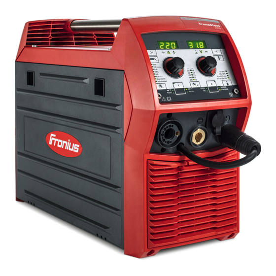
General Device concept The TransSteel (TSt) 2200c power source is a completely digitised, microprocessor- controlled power source. This power source is designed for the wel- ding of steel and can be used for the follo- wing welding processes: MIG/MAG welding MMA welding TIG welding with touchdown ignition The central control and regulation unit of the power source is coupled with a digital signal... -
Page 26: Application Areas
Application areas MIG/MAG welding MMA welding TIG welding... -
Page 27: Warning Notices On The Device
Warning notices Warning notices and safety symbols are affixed to the power source. These warning notic- on the device es and safety symbols must not be removed or painted over. They warn against incorrect operation, as this may result in serious injury and damage. Steel: 3-4 CrNi: 3-4 FCW: 3... - Page 28 Do not dispose of used devices with domestic waste. Dispose of them accord- ing to the safety rules. Keep hands, hair, clothing and tools away from moving parts. For example: Cogs Feed rollers Wirespools and welding wires Do not reach into the rotating cogs of the wire drive or into rotating drive com- ponents.
-
Page 29: Control Elements And Connections
Control elements and connections... -
Page 31: Synergic Central Control Panel
Synergic Central control panel General NOTE! Due to software updates, you may find that your device has certain func- tions that are not described in these operating instructions or vice versa. Individ- ual illustrations may also differ slightly from the actual controls on your device, but these controls function in exactly the same way. -
Page 32: Synergic Control Panel
Synergic control panel Function Spot welding indicator The spot welding indicator lights up if spot welding/stitch welding mode is select- ed and the SPt parameter (spot welding time/stitch welding time) in the Setup menu is not set to OFF 4-step stitch welding indicator The 4-step stitch welding indicator lights up if Spot welding/stitch welding mode is selected and The SPb parameter (spot welding/stitch welding pause time) is set to a value... - Page 33 Function "Parameter selection" button (left) For selecting the parameters listed below The relevant symbol lights up when a welding parameter is selected. Sheet thickness in mm or in. *) If the welding current to be selected is not known, it is sufficient to enter the sheet thickness.
- Page 34 Function "Parameter selection" button (left) For selecting the parameters listed below The relevant symbol lights up when a welding parameter is selected. Arc length correction For correcting the arc length Welding voltage in V *) Before the start of welding, the device automatically displays a standard val- ue based on the programmed parameters.
- Page 35 (10) (11) Function "Gas-test" button For setting the required gas flow rate on the gas pressure regulator/for filling the torch hosepack with shielding gas. When the "Gas-test" button is pressed, shielding gas will flow for 30 s. Press the button again to stop the gas flow prematurely. Adjusting dial (left) For changing the sheet thickness, welding current and wire speed parameters as well as changing parameters in the Setup menu...
-
Page 36: Keylock
(12) (18) (13) (14) (15) (16) (17) Function (12) "Material" button For selecting the filler metal to be used (13) "Save" button 1 For saving an EasyJob (14) "Mode" button For selecting the operating mode 2 T = 2-step mode 4 T = 4-step mode S 4 T = Special 4-step mode Spot welding/stitch welding... - Page 37 Press the "Parameter selection" button (right) Release the "Mode" and "Parameter selection" buttons Keylock activated: The message "CLO | SEd" appears on the displays. Keylock deactivated: The message "OP | En" appears on the displays.
-
Page 38: Connections, Switches And Mechanical Components
Connections, switches and mechanical components Safety WARNING! Operating the equipment incorrectly can cause serious injury and damage. Do not use the functions described until you have thoroughly read and understood the following documents: these operating instructions all the operating instructions for the system components, especially the safe- ty rules Front and rear Welding torch connection... -
Page 39: Side View
MIG/MAG shielding gas connec- (6) (7) tion socket For the shielding gas supply to the welding torch connection (1) Mains switch For switching the power source on and off Mains cable with strain relief de- vice TIG shielding gas connection so- cket For the shielding gas supply to the (-) - current socket (2) -
Page 41: Before Installation And Commissioning
Before installation and commission-... -
Page 43: General
General Safety WARNING! Incorrect operation or shoddy workmanship can cause serious injury or damage. All activities described in these operating instructions may only be carried out by trained and qualified personnel. All functions described in these op- erating instructions may only be used by trained and qualified personnel. Do not carry out any of the work or use any of the functions described until you have fully read and understood the following documents: these operating instructions... -
Page 44: Generator-Powered Operation
Generator-powered operation Generator-pow- The power source is generator-compatible. ered operation The maximum apparent power S of the power source must be known in order to select 1max the correct generator output. The maximum apparent power S of the power source is calculated as follows: 1max 1max 1max... -
Page 45: Mains Fuse Protection
Mains fuse protection Adjustable mains The mains fuse protection selected on the power source limits the power drawn in from the fuse protection mains and in turn the possible welding current. This prevents the automatic circuit breaker (e.g. in the fuse box) from tripping straight away. The desired mains fuse protection can be selected on the power source depending on the mains voltage and automatic circuit breaker used. - Page 46 TSt 2200c MV: Mains Country- Power source fuse Welding current limitation voltage specific set- rating ting 120 V 15 A MIG/MAG welding: max. 105 A; 80 A at 100 %* MMA welding: max. 90 A; 70 A at 100 %* TIG welding: max.
- Page 47 rent to switch off, the service code "toF" is displayed. A countdown immediately appears next to the "toF" indicator, which shows the remaining time until the power source is ready for welding again. After this time, the message disappears and the power source can be used again.
-
Page 49: Carrying Strap
Carrying strap... -
Page 51: Fitting The Carrying Strap
Fitting the carrying strap Fitting the carry- ing strap to the power source... -
Page 53: Mig/Mag
MIG/MAG... -
Page 55: Start-Up
Start-up Connecting a MIG/MAG welding torch NOTE! Before connecting the welding torch to the power source, equip the welding torch according to the welding torch Operating In- structions: fit wearing parts to the torch body, fit the inner liner. CAUTION! Risk of damage if the welding torch is not fully inserted. -
Page 56: Inserting The Feed Rollers
Inserting the feed NOTE! In order to achieve optimum wire electrode feed, the feed rollers must be rollers suitable for the diameter and alloy of the wire being welded. -
Page 57: Inserting The D100 Wirespool
Inserting the D100 wirespool Inserting the Inserting the D200 wirespool: D200 wirespool CAUTION! Risk of injury and material damage if the wirespool topples over be- cause the locking ring has been placed the wrong way around. Always secure the locking ring as shown below. -
Page 58: Feeding In The Wire Electrode
Feeding in the CAUTION! Risk of injury due to elasticity of spooled wire electrode. When insert- wire electrode ing the wire electrode into the wire drive, hold the end of the wire electrode firmly to avoid injuries caused by the wire springing back. -
Page 59: Setting The Contact Pressure
CAUTION! Risk of injury from emerging wire electrode. When pressing the "Wire threading" button/the torch trigger: Keep the welding torch away from your face and body Wear suitable protective goggles Do not point the welding torch at people Make sure that the wire electrode does not touch any conductive or earthed parts (e.g. -
Page 60: Connecting The Gas Cylinder
Standard values Smooth feed roll- Steel 3 - 4 CrNi 3 - 4 Standard values "Intermeshed" feed rollers Tubular cored elec- trodes Aluminium 1 - 3 Connecting the WARNING! There is a high risk of very serious injury and damage if a gas cylin- gas cylinder der falls over. -
Page 62: Adjusting The Brake Of The Wirespool Holders
Adjusting the brake of the wirespool holders General D200 wirespool holder: The brake of the D200 wirespool holder is factory-set to enable optimum braking of full wirespools with standard steel wire electrodes. However, in some applications, adjusting the brake can be advantageous. To do so, pro- ceed as described in section "Adjusting the brake of the D200 wirespool holder". -
Page 63: Adjusting The Brake Of The D200 Wirespool Holder
Adjusting the CAUTION! Risk of injury and material damage from an emerging wire electrode brake of the D200 and moving parts due to inadvertent activation of the power source. Before com- wirespool holder mencing work: Turn the power source mains switch to the "O" position Disconnect the power source from the mains Ensure that the power source remains disconnected from the mains until all work has been completed... -
Page 64: Description Of Mig/Mag Operating Modes
Description of MIG/MAG operating modes Symbols press hold release 2-step mode "2-step mode" is suitable for Tacking work Short weld seams 4-step mode "4-step mode" is suitable for longer weld seams. Special 4-step "Special 4-step mode" is ideal for welding in mode higher power ranges. -
Page 65: Spot Welding
Spot welding The "Spot welding" mode is suitable for welded joints on overlapped sheets. 2-step stitch The "2-step stitch welding" mode is suitable welding for welding short weld seams on thin sheets, to prevent the weld seams from dropping through the base material. 4-step stitch The "4-step stitch welding"... -
Page 66: Mig/Mag Standard Manual Welding
MIG/MAG standard manual welding General The MIG/MAG standard manual welding process is a MIG/MAG welding process with no synergic function. Changing one parameter does not result in any automatic adjustments to the other param- eters – all variable parameters must be adjusted individually. Available parame- The following parameters are available for MIG/MAG manual welding: ters... -
Page 67: Mig/Mag Standard Synergic Welding
MIG/MAG standard synergic welding MIG/MAG stand- Press the "Process" button to select SYNERGIC ard synergic Press the "Mode" button to select the desired MIG/MAG mode: welding 2-step mode 4-step mode S 4 T - Special 4-step mode Spot welding/stitch welding NOTE! Under certain circumstances, it may not be possible to change weld- ing parameters that have been set for a system component (remote control, etc.) on the control panel of the power source. -
Page 68: Spot And Stitch Welding
Spot and stitch welding General The spot and stitch welding modes are MIG/MAG welding processes. Spot welding is used on overlapping sheets that are only accessible on one side. Stitch welding is used for light-gauge sheets. As the wire electrode is not fed continuously, the weld pool can cool down during the inter- vals. -
Page 71: Start-Up
Start-up Commissioning... -
Page 72: Setting The Gas Pressure On The Welding Torch With Gas Cut-Off Valve
CAUTION! Risk of injury and damage from electric shock. As soon as the power source is switched on, the tungsten elec- trode in the welding torch is live. Make sure the electrode does not touch any persons or electrically conductive or earthed parts (e.g. the housing, etc.). -
Page 73: Description Of Tig Operating Modes
Description of TIG operating modes Symbols and their explanations Pull back and hold the Release the torch trigger Push forward and hold Release the torch trigger torch trigger forwards the torch trigger backwards Gas pre-flow time Gas post-flow time Starting-current phase: the temperature is Final current phase: to prevent crater raised gently at low welding current, so cracks or cavitations... -
Page 74: 4-Step Mode
4-step mode down 4-step mode with intermediate lowering I-2 Intermediate lowering means that the welder uses the torch trigger during the main current phase to lower the welding current to the specified reduced current I-2. Place the tungsten electrode onto the workpiece and then pull the torch trigger back and hold =>... -
Page 75: Pulse Welding
Pulse welding Pulse welding Pulse welding is welding with a pulsing welding current. It is used for out-of-position weld- ing of steel pipes or when welding thin sheets. In these applications, the welding current set at the start of welding is not always ideal for the whole welding process: if the amperage is too low, the base material will not melt sufficiently if overheating occurs, the liquid weld pool may drip. -
Page 77: Rod Electrode
Rod electrode... -
Page 79: Start-Up
Start-up Preparatory work NOTE! Check the rod electrode packaging to determine whether the rod electrode is for (+) or (-) welding. CAUTION! Risk of injury and damage from electric shock. As soon as the power source is switched on, the rod electrode is live. Make sure the rod electrode does not touch any persons or electrically conductive or earthed parts (e.g. -
Page 80: Mma Welding
MMA welding Press the "Process" button to select STICK Set the desired welding current Power source is ready for welding... -
Page 81: Functions For Optimising The Welding Process
Functions for optimising the welding process Arc-force dynam- The arc-force dynamic is used to influence the short-circuiting dynamic at the moment of droplet transfer. = hard, stable arc 0 = neutral arc + = soft, low-spatter arc HotStart (Hti) This function is activated at the factory. function Advantages Improved ignition properties, even when using electrodes with poor ignition properties... -
Page 83: Easyjobs
EasyJobs... -
Page 85: Saving And Retrieving Easyjobs
Saving and retrieving EasyJobs General The "Save" buttons allow two EasyJobs to be saved. The adjustable parameters on the control panel are saved as EasyJobs. NOTE! Setup parameters are not saved as EasyJobs. Saving an Easy- Press and hold one of the "Save" buttons to save the current settings on the control panel, e.g.: The left indicator displays "Pro"... -
Page 87: Setup Menu
Setup menu... -
Page 89: Operation
Operation Operation NOTE! Accessing the Setup menu is described with reference to the MIG/MAG standard synergic (SYNERGIC) welding process. Access is the same for the oth- er welding processes. Accessing the Setup menu: Press the "Process" button to select the SYN- ERGIC welding process (to access the Setup menu for MIG/MAG standard manual welding, press the "Process"... -
Page 90: Parameters For Mig/Mag Standard Manual Welding
Parameters for MIG/MAG standard manual welding Parameters for Gas pre-flow time MIG/MAG stand- Unit: Seconds ard manual weld- Setting range: 0 - 9.9 Factory setting: 0.1 Gas post-flow time Unit: Seconds Setting range: 0 - 9.9 Factory setting: 0.5 Feeder inching speed Unit: m/min (ipm) Setting range: 1 - 18.5 (39.37 - 728.35) Factory setting: 10 (393.7) - Page 91 NOTE! If the power source is reset, the majority of the applied settings are deleted. The following values remain: Welding circuit resistance and welding circuit inductivity Country-specific setting Second level of the Setup menu (see "Setup menu - level 2")
-
Page 92: Parameters For Mig/Mag Standard Synergic Welding
Parameters for MIG/MAG standard synergic welding Parameters for Gas pre-flow time MIG/MAG stand- Unit: Seconds ard synergic Setting range: 0 - 9.9 welding Factory setting: 0.1 Gas post-flow time Unit: Seconds Setting range: 0 - 9.9 Factory setting: 0.5 Slope Unit: Seconds Setting range: 0 - 9.9 Factory setting: 1... - Page 93 NOTE! The ignition time-out function (Ito) is a safety feature – if the power source determines that no ignition has occurred after the preset wire length has been fed, wirefeeding is stopped. Spot welding time Unit: Seconds Setting range: 0.3 - 5 Factory setting: 1 Spot pause time Unit: Seconds...
-
Page 94: Parameters For Tig Welding
Parameters for TIG welding Parameters for Pulse frequency TIG welding Unit: Hertz Setting range: OFF; 1 - 990 (up to 10 Hz: in 0.1 Hz increments) (up to 100 Hz: in 1 Hz increments) (over 100 Hz: in 10 Hz increments) Factory setting: OFF UpSlope Unit: Seconds... -
Page 95: Parameters For Mma Welding
Parameters for MMA welding Setup parameters HotStart current for MMA welding Unit: % Setting range: 100 - 200 Factory setting: 150 Hot current time Unit: Seconds Setting range: 0 - 2.0 Factory setting: 0.5 Anti-stick function Unit: - Setting range: On, OFF Factory setting: OFF Reset power source to factory settings Press and hold one of the "Parameter selection"... -
Page 97: Setup Menu - Level 2
Setup menu - Level 2... -
Page 99: Operation
Operation Operation Accessing the Setup menu: Press the "Process" button to select the SYN- ERGIC welding process (to access the Setup menu for MIG/MAG standard manual welding, press the "Process" button and select MANU- Press and hold the "Mode" button Press the "Process"... -
Page 100: Parameters For Mig/Mag Standard Manual Welding
Parameters for MIG/MAG standard manual welding Parameters for Country-specific setting (Standard/USA) Std/US MIG/MAG welding Unit: - Setting range: Std, US (Standard/USA) If Std is selected, the EURO welding programs are used as stated in the welding program table. If US is selected, the US welding programs are used as stated in the welding pro- gram table. -
Page 101: Parameters For Mig/Mag Standard Synergic Welding
Parameters for MIG/MAG standard synergic welding Parameters for Country-specific setting (Standard/USA) Std/US MIG/MAG welding Unit: - Setting range: Std, US (Standard/USA) If Std is selected, the EURO welding programs are used as stated in the welding program table. If US is selected, the US welding programs are used as stated in the welding pro- gram table. -
Page 102: Parameters For Mma Welding
Parameters for MMA welding Parameters for Country-specific setting (Standard/USA) Std/US MMA welding Unit: - Setting range: Std, US (Standard/USA) If Std is selected, the EURO welding programs are used as stated in the welding program table. If US is selected, the US welding programs are used as stated in the welding pro- gram table. -
Page 103: Parameters For Tig Welding
Parameters for TIG welding Parameters for Country-specific setting (Standard/USA) Std/US TIG welding in the Setup menu Unit: - level 2 Setting range: Std, US (Standard/USA) Factory setting: Standard version: Std (measurements: cm/mm) USA version: US (measurements: inches) Mains fuse protection The maximum possible welding power is limited by the rating of the mains fuse protection. -
Page 105: Optimising Welding Quality
Optimising welding quality... -
Page 107: Measuring Welding Circuit Resistance R
Measuring welding circuit resistance r General Measuring the welding circuit resistance r makes it possible to have a constant welding re- sult at all times, even with hosepacks of different lengths. The welding voltage at the arc is then always precisely regulated, regardless of the length and cross-sectional area of the hosepack. -
Page 108: Displaying Welding Circuit Inductivity L
Displaying welding circuit inductivity L General Laying of the hosepacks has a significant effect on welding circuit inductivity and therefore affects the welding process. It is important to lay the hosepacks correctly in order to obtain the best possible welding result. Displaying weld- The setup parameter "L"... -
Page 109: Troubleshooting And Maintenance
Troubleshooting and maintenance... -
Page 111: Display Service Parameters
Display service parameters Service parame- Various service parameters can be retrieved by pressing the left and right-hand "Parame- ters ter selection" buttons at the same time. Opening the display Press and hold the "Parameter selection" button (left) Press the "Parameter selection" button (right) Release the "Parameter selection"... -
Page 112: Troubleshooting
Troubleshooting Safety WARNING! Work that is carried out incorrectly can cause serious injury and dam- age. All the work described below must only be carried out by trained and quali- fied personnel. Do not carry out any of the work described below until you have fully read and understood the following documents: This document all the operating instructions for the system components, especially the safe-... - Page 113 No welding current Mains switch is on, one of the overtemperature service codes "to" is displayed. Detailed information on the service codes "to0" to "to6" can be found in the section "Displayed ser- vice codes". Cause: Overloading Remedy: Check duty cycle Cause: Thermostatic automatic circuit breaker has been tripped Remedy:...
- Page 114 Irregular wire speed Cause: Braking force has been set too high Remedy: Loosen the brake Cause: Hole in the contact tip is too narrow Remedy: Use a suitable contact tip Cause: Faulty inner liner in welding torch Remedy: Check the inner liner for kinks, dirt, etc. and replace if necessary Cause: The wirefeeder rollers are not suitable for the wire electrode being used Remedy:...
-
Page 115: Displayed Service Codes
Displayed service If an error message that is not described here appears on the displays, proceed as follows codes to resolve the problem: Turn the power source mains switch to the "O" position Wait 10 seconds Turn the mains switch to the "I" position If the error occurs again despite several attempts to eliminate it, or if the troubleshooting measures listed here are unsuccessful: Make a note of the error message displayed... - Page 116 to1 | xxx Note: xxx stands for a temperature value Cause: Overtemperature on the booster located in the power source Remedy: Allow power source to cool down, check air filter and clean if necessary, check that fan is on to2 | xxx Note: xxx stands for a temperature value Cause: Overtemperature in the secondary circuit of the power source...
- Page 117 tu1 | xxx Note: xxx stands for a temperature value Cause: Undertemperature on the booster located in the power source Remedy: Place power source in a heated room and allow it to warm up tu2 | xxx Note: xxx stands for a temperature value Cause: Undertemperature in the power source secondary circuit Remedy:...
-
Page 118: Care, Maintenance And Disposal
Care, maintenance and disposal General Under normal operating conditions, the welding system requires only a minimum of care and maintenance. However, it is vital to observe some important points to ensure the weld- ing system remains in a usable condition for many years. Safety WARNING! Work that is carried out incorrectly can cause serious injury and dam- age. -
Page 119: As Required, At Least Every Two Months
As required, at least every two months CAUTION! Risk of damage. Ensure that the air filter is dry when it is fitted. Every 6 months Dismantle device side panels and clean inside of device with dry reduced compressed NOTE! Risk of damage to electronic components. Do not bring air nozzle too close to electronic components. -
Page 120: Brake Setup On The Wirespool Holders
Brake setup on the wirespool holders Brake setup on the D100 wire- D100 spool holder Brake setup on WARNING! Fitting the equipment incorrectly can cause serious injury and dam- the D200 wire- age. spool holder Do not dismantle the brake. Maintenance and servicing of brakes is to be carried out by trained, qualified personnel only. -
Page 121: Technical Data
Technical data... -
Page 123: Technical Data
Technical data Special voltages For devices designed for special voltages, the technical data on the rating plate applies. Explanation of Duty cycle (D.C.) is the proportion of time in a 10-minute cycle at which the device may be the term "duty cy- operated at its rated output without overheating. -
Page 124: Tst 2200C
TSt 2200c Mains voltage (U 230 V Max. effective primary current (I 16 A 1eff Max. primary current (I 26 A 1max Mains fuse protection 16 A slow-blow Mains voltage tolerance -20 / +15% Mains frequency 50/60 Hz Cos phi (1) 0.99 Max. - Page 125 Wirespool diameter max. 200 mm max. 7.87 in. Wirespool weight max. 6.8 kg max. 14.99 lb Max. noise emission (LWA) 65.5 dB Interface to a 230 V, 50 Hz public grid...
-
Page 126: Tst 2200C Mv
TSt 2200c MV Mains voltage (U 120 V Max. effective primary current (I 15 A 1eff Max. primary current (I 20 A 1max Mains fuse protection 15 A slow-blow Mains voltage (U 120 V Max. effective primary current (I 20 A 1eff Max. - Page 127 Rod electrode 20.4 - 27.2 V 10.4 - 19.2 V Open circuit voltage (U peak / U r.m.s) 90 V Degree of protection IP 23 Type of cooling Overvoltage category Pollution level according to IEC60664 Safety symbols S, CE, CSA Dimensions l x w x h 560 x 215 x 370 mm 22.05 x 8.46 x 14.57 in.
- Page 128 FRONIUS INTERNATIONAL GMBH Froniusplatz 1, A-4600 Wels, Austria Tel: +43 (0)7242 241-0, Fax: +43 (0)7242 241-3940 E-Mail: sales@fronius.com www.fronius.com www.fronius.com/addresses Under http://www.fronius.com/addresses you will find all addresses of our Sales & service partners and Locations...
Need help?
Do you have a question about the TransSteel 2200c and is the answer not in the manual?
Questions and answers