Table of Contents
Advertisement
Quick Links
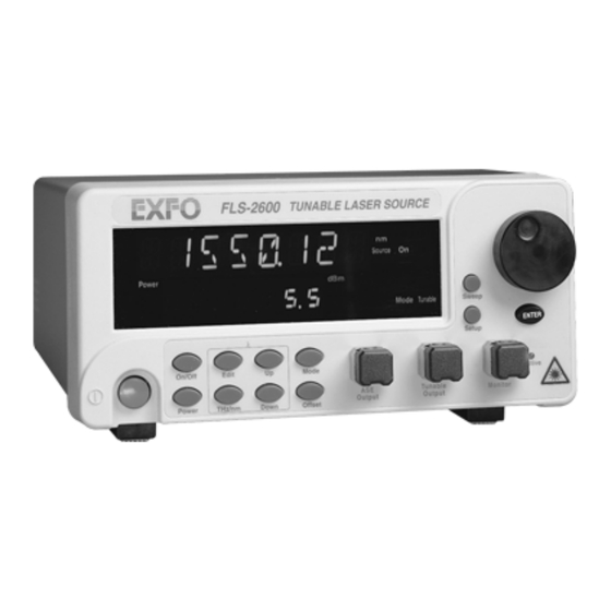
Exfo FLS-2600-EI
Tunable Laser Source
A l l t r a d e m a r k s , b r a n d n a m e s , a n d b r a n d s a p p e a r i n g h e r e i n a r e t h e p r o p e r t y o f t h e i r r e s p e c t i v e o w n e r s .
• C r i t i c a l a n d e x p e d i t e d s e r v i c e s
• I n s t o c k / R e a d y - t o - s h i p
Artisan Scientific Corporation dba Artisan Technology Group is not an affiliate, representative, or authorized distributor for any manufacturer listed herein.
Limited Availability
Used and in Excellent Condition
Buy Today!
https://www.artisantg.com/59014-1
• We b u y y o u r e x c e s s , u n d e r u t i l i z e d , a n d i d l e e q u i p me n t
• F u l l - s e r v i c e , i n d e p e n d e n t r e p a i r c e n t e r
Advertisement
Table of Contents

Related Manuals for EXFO FLS-2600-EI


Summary of Contents for EXFO FLS-2600-EI
- Page 1 Exfo FLS-2600-EI Tunable Laser Source Limited Availability Used and in Excellent Condition Buy Today! https://www.artisantg.com/59014-1 A l l t r a d e m a r k s , b r a n d n a m e s , a n d b r a n d s a p p e a r i n g h e r e i n a r e t h e p r o p e r t y o f t h e i r r e s p e c t i v e o w n e r s .
-
Page 2: Tunable Laser Source
FLS-2600 Tunable Laser Source Instruction Manual Second Edition P/N: MAN-141-I .2ACE If the equipment described herein bears the symbol, the said equipment complies with the European Community Directive and Standards found in the Declaration of Conformity. If the equipment described herein bears an statement, the said equipment complies with the relevant Federal Communications Commission standards. - Page 3 EXFO Electro-Optical Engineering Inc. (EXFO). Information provided by EXFO is believed to be accurate and reliable. However, no responsibility is assumed by EXFO for its use nor for any infringements of patents or other rights of third parties that may result from its use.
-
Page 4: Table Of Contents
Contents Contents Certification Information......................vi 1 Introduction ....................1 FLS-2600 General Description....................1 FLS-2600 Main Applications ....................1 FLS-2600 Models and Connector Types ................... 2 2 Safety Information ..................3 Safety Conventions........................3 General Safety Information ..................... 3 3 Getting Started ..................... 7 Hardware Description...................... - Page 5 Contents Starting the Sweep........................ 31 Stopping the Sweep......................32 Saving a Sweep Configuration ....................32 Recalling a Sweep Configuration................... 34 7 Remote Control ...................35 Setting the FLS-2600 for Remote Control................35 Communication Parameters ....................36 Standard Status Data Structure..................... 37 Command Structure......................
- Page 6 Figures Figures Figure 2-1. Laser Warning Label .................... 4 Figure 3-1. FLS-2600 Front Panel ................... 7 Figure 3-2. FLS-2600 Back Panel .................... 8 Figure 3-3. FLS-2600 Product Nameplate ................9 Figure 3-4. RS-232 Connector Pinout ..................9 Figure 3-5. Menu Diagram ....................11 Figure 4-1.
-
Page 7: Certification Information
Consult the dealer or an experienced radio/TV technician for help. ➤ ARNING Changes or modifications not expressly approved by EXFO Electro-Optical Engineering Inc. could void the user’s authority to operate the unit. This unit is equipped with a shielded three-wire power cord and plug. - Page 8 EXFO, and externally, at an independent, qualified laboratory. All pre-qualification tests were performed at EXFO while all final tests were performed at UltraTech Engineering Labs Inc., a renowned test laboratory from Mississauga, Canada. This guarantees the unerring objectivity and authoritative compliance of all test results.
- Page 9 This page is intentionally left blank. Artisan Technology Group - Quality Instrumentation ... Guaranteed | (888) 88-SOURCE | www.artisantg.com...
-
Page 10: Introduction
Introduction FLS-2600 General Description The FLS-2600 Tunable Laser Source combines a tunable laser with a broadband source covering the 1520 to 1570 nm range. The FLS-2600 has been specially designed for testing passive components. Its coherence length is perfectly suited for detecting parasitic etalon or other interference effects inside components. -
Page 11: Fls-2600 Models And Connector Types
The FLS-2600 is particularly well suited to the most demanding laboratory and manufacturing qualification applications. FLS-2600 Models and Connector Types Model Connector Type FLS-2600B-EA-YY EXFO APC Universal Interface FLS-2600B-EI-YY EXFO UPC Universal Interface Options YY FC connector adapter ST connector adapter (UPC only) -
Page 12: Safety Information
Safety Information Safety Conventions You should understand the following conventions before using the product described in this manual: ARNING Refers to a potential personal hazard. It requires a procedure that, if not correctly followed, may result in bodily harm or injury. Do not proceed beyond a ARNING unless you understand and meet the required conditions. -
Page 13: Safety Precautions
Failure to comply with these precautions or with specific indications elsewhere in this manual violates safety standards of intended use of the unit. EXFO assumes no liability for the user's failure to comply with these requirements. -
Page 14: Power Cable
Safety Information General Safety Information The unit must be positioned in a way not to block the ventilation holes ➤ located on each side of the unit. Any adjustments, maintenance, and repair of opened units under ➤ voltage should be avoided and carried out only by skilled personnel aware of the hazards involved. - Page 15 Safety Information General Safety Information ARNING To avoid electrical shock, do not operate the unit if there are signs of damage to any part of the outer surface (covers, panels, etc.). To avoid serious injury, the following precautions must be observed before powering on the unit.
-
Page 16: Getting Started
Getting Started This section presents a description of the hardware, provides information on how to turn the FLS-2600 on and off, and describes the software main menu. Hardware Description Front Panel Variable speed selection knob for menu navigation and parameter setting LED indicating that the tunable output is on Sweep menu access... -
Page 17: Figure 3-2. Fls-2600 Back Panel
Getting Started Hardware Description Back Panel Fuse holder Serial port GPIB port (RS-232 DTE) Power inlet FLS-2600-E A-1.0 November 1998 12345-2P Ground Figure 3-2. FLS-2600 Back Panel Note: Your FLS-2600 may slightly differ from the above illustration. Product Nameplate The product nameplate, shown in Figure 3-3, provides the following information: the part number (P/N) identifying configuration and connector type ➤... -
Page 18: Turning The Fls-2600 On And Off
Getting Started Turning the FLS-2600 On and Off Part number Ver. Version number FLS-2600-E A-1.0 Mfg. Manufacturing date November 1998 12345-AB Serial number date Figure 3-3. FLS-2600 Product Nameplate RS-232 Connector Pinout The RS-232 connector (serial port) at the back of the FLS-2600 uses a DTE pinout configuration. -
Page 19: Resetting The Fls-2600
Getting Started Resetting the FLS-2600 Upon startup, the unit beeps twice, performs a self-test, and then enters the main menu (in tunable mode) with the same settings that were active when the unit was last turned off, with the source deactivated. When the unit is turned off, the following items remain in non-volatile memory: current power setting... -
Page 20: Accessing Menus
Getting Started Accessing Menus Accessing Menus The blue buttons to the right of the display give access to single-level menus: Sweep and Setup. Access to these menus is possible in any situation of the main menu in tunable operation, even while the source is active. - Page 21 This page is intentionally left blank. Artisan Technology Group - Quality Instrumentation ... Guaranteed | (888) 88-SOURCE | www.artisantg.com...
-
Page 22: Using The Fls-2600 Main Menu
Using the FLS-2600 Main Menu The FLS-2600 main menu gives access to the following options (which are explained in the next sections): wavelength mode (see Setting the Wavelength on page 13) ➤ power mode (see Setting the Output Power on page 14) ➤... -
Page 23: Setting The Output Power
Using the FLS-2600 Main Menu Setting the Output Power 2. Rotate the knob clockwise or counter-clockwise until the desired wavelength is displayed. (You can select a wavelength between 1520.00 and 1570.00 nm at a resolution of 0.01 nm.) The Press Enter marker starts blinking on the display. -
Page 24: Activating/Deactivating The Source
Using the FLS-2600 Main Menu Activating/Deactivating the Source 2. Rotate the knob clockwise or counter-clockwise until the desired output power level is displayed. You can select a power level up to 6.0 dBm (see below) by increments of 0.1 dBm. If you change the power while the source is active, the new output power changes accordingly (i.e., with no need to validate the new output power). -
Page 25: Setting The Source
Using the FLS-2600 Main Menu Setting the Source 2. After approximately one second, the Active LED lights up on the fascia to indicate that the source is active at the wavelength, at the output power, and in the mode currently selected. 3. -
Page 26: Setting The Wavelength Display Unit
Using the FLS-2600 Main Menu Setting the Wavelength Display Unit Setting the Wavelength Display Unit Press THz/nm to toggle between the nanometer (nm) and terahertz (THz) wavelength display units. The nm or THz marker appears on the display according to your selection. Wavelength unit Wavelength in THz unit Power... -
Page 27: Figure 4-6. Offset Activated
Using the FLS-2600 Main Menu Activating the Wavelength Offset To activate the offset, press Offset. The Offset On marker appears on the display, and the wavelength displayed changes according to the offset value. Power Mode Tunable Offset On Offset activated Figure 4-6. -
Page 28: Using The Fls-2600 Setup Menu
Using the FLS-2600 Setup Menu The first item in the Setup menu is the shortlist of wavelengths (LAMBDA mode), i.e., the preset wavelengths that will be readily available in the main menu by simply pressing Up or Down. Up to 80 wavelengths can be stored in the shortlist for each configuration (see Saving a Setup Configuration on page 23). -
Page 29: Figure 5-1. Default Wavelength Display
Using the FLS-2600 Setup Menu Adding a Wavelength to the Shortlist Edit Default wavelength Figure 5-1. Default Wavelength Display 5. Rotate the knob clockwise or counter-clockwise until the desired wavelength is displayed, then press ENTER (pressing Edit at this step will cancel the operation). -
Page 30: Deleting A Wavelength From The Shortlist
Using the FLS-2600 Setup Menu Deleting a Wavelength from the Shortlist Deleting a Wavelength from the Shortlist To delete a wavelength from the shortlist, 1. Press Setup. 2. Press ENTER to enter LAMBDA mode. The Edit marker appears in the lower part of the display. -
Page 31: Setting The Display Intensity
Using the FLS-2600 Setup Menu Setting the Display Intensity 3. Press ENTER. The Edit marker starts blinking in the lower part of the display. 4. Rotate the knob clockwise or counter-clockwise until the desired offset value is displayed, then press ENTER. You can select a value between -99.99 and 99.99 nm (i.e., between -12.564 and 12.564 THz if the THz unit was selected in the main menu). -
Page 32: Saving A Setup Configuration
Using the FLS-2600 Setup Menu Saving a Setup Configuration Note: Setting the dimmer to OFF turns off the display. Press any key to turn the display back on. 5. To exit the Setup menu, press Setup. Saving a Setup Configuration Once the FLS-2600 has been customized for a specific application or user, it is possible to save the configuration of the parameters that have been set in the Setup menu, with the exception of the dimmer status and the... -
Page 33: Recalling A Setup Configuration
Using the FLS-2600 Setup Menu Recalling a Setup Configuration 4. Rotate the knob until the desired configuration number is displayed, then press ENTER. It takes a few seconds to save a setup configuration. Note: Upon startup, the last configuration saved will be recalled. 5. -
Page 34: Displaying The Software Version Number
Using the FLS-2600 Setup Menu Displaying the Software Version Number Displaying the Software Version Number This option allows you to see the software version currently installed in the FLS-2600. No action is possible here. 1. Press Setup. 2. Rotate the knob clockwise until VERSION is displayed. Current software version number Figure 5-6. - Page 35 This page is intentionally left blank. Artisan Technology Group - Quality Instrumentation ... Guaranteed | (888) 88-SOURCE | www.artisantg.com...
-
Page 36: Using The Fls-2600 Sweep Menu
Using the FLS-2600 Sweep Menu The Sweep menu allows access to automatic wavelength scans and program speeds according to user-defined parameters. Setting the Start Wavelength of the Sweep 1. Press Sweep. A default start wavelength is suggested. Default start wavelength Figure 6-1. -
Page 37: Setting The End Wavelength Of The Sweep
Using the FLS-2600 Sweep Menu Setting the End Wavelength of the Sweep Setting the End Wavelength of the Sweep To set the end wavelength of the sweep, 1. Press Sweep. 2. Rotate the knob clockwise until LM-STOP is displayed. A default end wavelength is suggested. -
Page 38: Setting The Number Of Sweeps
Using the FLS-2600 Sweep Menu Setting the Number of Sweeps Setting the Number of Sweeps 1. Press Sweep. 2. Rotate the knob clockwise until REPEAT is displayed. The default setting is 1, i.e., the sweep will be executed only once by default. Default number of repetitions Figure 6-3. -
Page 39: Setting The Speed Of The Sweep
Using the FLS-2600 Sweep Menu Setting the Speed of the Sweep Setting the Speed of the Sweep To set the speed of the sweep, 1. Press Sweep. 2. Rotate the knob clockwise until SPEED is displayed. The default setting is 0.10 nm/s, i.e., the sweep will be executed at a speed of 0.10 nm per second by default. -
Page 40: Starting The Sweep
Using the FLS-2600 Sweep Menu Starting the Sweep Starting the Sweep To start the sweep, 1. Set the wavelength, the output power, the display mode, and the wavelength display unit, and activate the tunable source, as explained in the Using the FLS-2600 Main Menu chapter on page 13. 2. -
Page 41: Stopping The Sweep
Using the FLS-2600 Sweep Menu Stopping the Sweep Stopping the Sweep To stop the sweep, 1. Press Sweep. STOP is immediately displayed when performing a sweep. Figure 6-6. Stop Display 2. Press ENTER. The sweep is stopped, and the unit beeps. Saving a Sweep Configuration Once the FLS-2600 has been customized for a specific application or user, it is possible to save the configuration of the parameters that have been set... -
Page 42: Figure 6-7. Current Configuration Number
Using the FLS-2600 Sweep Menu Saving a Sweep Configuration To save a sweep configuration, 1. Press Sweep. 2. Rotate the knob clockwise until SAVE is displayed. The current configuration number appears. Current configuration number Figure 6-7. Current Configuration Number 3. Press ENTER. The Edit marker starts blinking in the lower part of the display. -
Page 43: Recalling A Sweep Configuration
Using the FLS-2600 Sweep Menu Recalling a Sweep Configuration Recalling a Sweep Configuration Once you have saved a sweep configuration, you can recall it at any time. 1. Press Sweep. 2. Rotate the knob clockwise until RECALL is displayed. Configuration number Figure 6-8. -
Page 44: Remote Control
Remote appears in the lower left-hand corner of the display. Note: If you have already designed a GPIB program to control a tunable laser source from EXFO’s IQ series (IQ-2600), you can reuse sections for the FLS-2600. Setting the FLS-2600 for Remote Control To remotely control the FLS-2600, you need to set a GPIB address or activate the RS-232 port. -
Page 45: Communication Parameters
Remote Control Communication Parameters 3. Press ENTER. The Edit marker starts blinking in the lower part of the display. 4. Rotate the knob clockwise or counter-clockwise to enter the new setting: A numbered setting represents a GPIB address (between 1 and ➤... -
Page 46: Standard Status Data Structure
Remote Control Standard Status Data Structure For RS-232 Communication EOS bytes Stop bits 1 bit Baud rate 9600 bps Flow control None Parity None Activation see Section Data bits 8 bits Table 7-2. RS-232 Communication Parameters Note: EOS means “End of String”. EOI means “End or Identify”. Standard Status Data Structure Figure 7-1 on next page illustrates the four common Status and Enable registers as defined by IEEE 488.3. - Page 47 Remote Control Standard Status Data Structure Device Device Questionable Questionable Dependent Error Dependent Error Status Status Execution Error Execution Error Message Event Status Available Summary Bit Command Error Command Error Event Status Message Summary Bit Available User Request User Request Master Summary Request Service / Status...
-
Page 48: Figure 7-1. Standard Status Data Structures (Ieee 488.3)
Remote Control Standard Status Data Structure Standard Event Status Register (ESR) & & & & & & & & Standard Event Status Enable Register (ESE) Output Queue not Empty read by serial poll ESB MAV Status Byte Service Request Register Generation (STB) read by *STB? -
Page 49: Command Structure
Remote Control Command Structure An SRQ is forced when a bit is set in the STB and, at the same time, the corresponding SRE bit is set. When the SRQ is generated, the RQS bit is set to 1, and remains set until read by a serial poll. Once the RQS is read, it returns to 0. -
Page 50: General Commands-Quick Reference
Remote Control General Commands—Quick Reference General Commands—Quick Reference The FLS-2600 recognizes the main commands identified in IEEE 4888.3. The following table summarizes these commands. Command Function *CLS Clear status command *ESE Standard event status enable command *ESE? Standard event status enable query *ESR? Standard event status register query *IDN? -
Page 51: General Commands
Remote Control General Commands General Commands *CLS Description This command sets the contents of the Standard Event Register (ESR), the Status Byte Register (STB), and the Error Queue (ERR) to zero. This command is commonly used to clear the status registers before enabling SRQ. Note that the output queue, Standard Event Status Enable Register (ESE), and Service Request Enable Register (SRE) are not affected. - Page 52 A binary integer between 0 and 255. *IDN? Description This query reads the FLS-2600 system identification string. Syntax *IDN? Response “EXFO E.-O. Eng FLS-2600 Vxx.xx”, where xx.xx is the current product version. *LOK Description This command is used to set the Remote Lockout programming state. Syntax...
- Page 53 Remote Control General Commands *OPC? Description This query puts an ASCII 1 in the output queue when the content of the input queue has been processed. This query is useful to prevent another command from processing until the current command is complete. Syntax *OPC? Response...
- Page 54 Remote Control General Commands *SRE Description This command sets bits in the Service Request Enable Register (SRE; initial value is 255) and enables the corresponding bit in the Status Byte Register (STB). The command can be used to select which events can initiate a service request. Syntax *SRE<space><value>...
- Page 55 Remote Control General Commands *TST? Description This query initiates an internal self-test and returns a binary value indicating the results of the test. Syntax *TST? Response A binary value: “0”-test is complete with no errors “1”-test is complete with errors *WAI Description Not supported Syntax...
-
Page 56: System:version
SYSTem:VERSion? Description This query reads the FLS-2600 identification string. Syntax SYST:VERS? Response “EXFO E.-O. Eng FLS-2600 Vxx.xx”, where xx.xx is the current product version. Tunable Laser Source Artisan Technology Group - Quality Instrumentation ... Guaranteed | (888) 88-SOURCE | www.artisantg.com... -
Page 57: Specific Commands-Quick Reference
Remote Control Specific Commands—Quick Reference Specific Commands—Quick Reference The following table contains a summary of the FLS-2600 specific commands. Parameter/ Command Description Response ASE? (0|1) Source available? MODE <0|1> Set source mode MODE? (0|1) Get source mode STAT <0|1> Turn source on or off STAT? (0|1) Source active? - Page 58 Remote Control Specific Commands—Quick Reference Parameter/ Command Description Response PROG? (9999.99;99.99; Set sweep parameters 999:99:99) [NM] (999.999;9.999; 9999:99:99) [THZ] SOUR REPE <0|1> Set loop REPE? (0|1) Loop active? <0|1> Set reverse function REV? (0|1) Reverse function active? SPAN? (9999.99) [NM] Get wavelength span (999.999) [THZ] STAT...
- Page 59 Remote Control Specific Commands—Quick Reference Parameter/ Command Description Response UNIT WAVE <0|1> Set wavelength unit WAVE? (0|1) Get wavelength unit Table 7-5. Specific Commands Quick Reference (Part 3 of 3) The commands are fully explained hereafter. FLS-2600 Artisan Technology Group - Quality Instrumentation ... Guaranteed | (888) 88-SOURCE | www.artisantg.com...
-
Page 60: Specific Commands
Remote Control Specific Commands Specific Commands OUTput:ASE? Description This query returns a value indicating whether the ASE option is available on the tunable laser source. Syntax OUT:ASE? Response A boolean value indicating whether the ASE option is available on the FLS-2600 Tunable Laser Source: “0”-the ASE option is not available “1”-the ASE option is available Example... -
Page 61: Output:state
Remote Control Specific Commands OUTput:MODE? Description This query returns the current source mode (tunable or ASE). Syntax OUT:MODE? Response A boolean value representing the current source mode: “0”-the source is in tunable mode “1”-the source is in ASE mode Example OUT:MODE? See also OUT:ASE? and OUT:MODE... - Page 62 Remote Control Specific Commands OUTput:STATe? Description This query returns the current source state. Syntax OUT:STAT? Response A boolean value representing the current source state: “0”-the source is deactivated “1”-the source is activated Example OUT:STAT? SOURce:POWer:LEVel:IMMediate:AMPLitude Description This command is used to set the source output power (in dBm). Syntax SOUR:POW:LEV:IMM:AMPL<space><power>...
- Page 63 Remote Control Specific Commands SOURce:POWer:LEVel:IMMediate:AMPLitude? Description This query returns the source output power (in dBm). Syntax SOUR:POW:LEV:IMM:AMPL? Response The current source output power (in dBm) in the “±9.9” format. Note When in ASE mode, this command will return an invalid value. In case of no power, the “-----”...
- Page 64 Remote Control Specific Commands SOURce:POWer:LIMit:LOW? Description This query returns the minimum source output power (in dBm) that can be set with the SOUR:POW:LEV:IMM:AMPL command. Syntax SOUR:POW:LIM:LOW? Response The minimum source output power (in dBm) in the “±9.9” format. Example SOUR:POW:LIM:LOW? See also SOUR:POW:LEV:IMM:AMPL, SOUR:POW:LEV:IMM:AMPL?, SOUR:POW:LIM:HIGH?, and SOUR:POW:LIM:STEP?
- Page 65 Remote Control Specific Commands SOURce:SWEep:CENTer? Description This query returns the central wavelength for the current sweep program in the current spectral units (nm or THz). Syntax SOUR:SWE:CENT? Response The central wavelength for the current sweep program in the current spectral units in the “9999.99” (nm) or “999.999” (THz) format.
- Page 66 Remote Control Specific Commands SOURce:SWEep:PROGram? Description This function is used to set the parameters for a sweep program. During a sweep program, the application sweeps between two wavelengths: the minimum and maximum wavelengths. This function also returns the validated parameters. Syntax SOUR:SWE:PROG?<space><central>,<span>,<time>...
- Page 67 Remote Control Specific Commands SOURce:SWEep:REPEat Description This command is used to specify whether or not you want the sweep program to loop. If activated, the sweep program will loop the number of times set by the SOUR:SWE:COUN command. Syntax SOUR:SWE:REPE<space><loop> Parameters The <loop>...
- Page 68 Remote Control Specific Commands SOURce:SWEep:REV Description This command is used to enable and disable the sweep reverse function. When the sweep reverse function is enabled, the sweep program is performed in both directions: in the wavelength ascending and descending order. Syntax SOUR:SWE:REV<space><sweep>...
- Page 69 Remote Control Specific Commands SOURce:SWEep:SPAN? Description This query returns the wavelength range to be swept below and above the central wavelength. Syntax SOUR:SWE:SPAN? Response A value representing the wavelength range to be swept below and above the central wavelength. The current spectral measurement units apply (nm or THz).
- Page 70 Remote Control Specific Commands SOURce:SWEep:STATe? Description This query returns a value indicating the state of the sweep program. Syntax SOUR:SWE:STAT? Response A boolean value representing the current state of the sweep program: “1”-the sweep program is in progress “0”-the sweep program is not in progress Example SOUR:SWE:STAT? SOURce:SWEep:TIME?
- Page 71 Remote Control Specific Commands SOURce:WAVElength:LENGth Description This command selects a new source wavelength. The current spectral units (nm or THz) apply. Syntax SOUR:WAVE:LENG<space><wave> Parameters The <wave> parameter represents the new wavelength in the “9999.99” (nm) or “999.999” (THz) format. Note This function cannot be performed if the application is running in ASE or Sweep mode.
- Page 72 Remote Control Specific Commands SOURce:WAVElength:LIMit:HIGH? Description This query returns the maximum wavelength that can be set with the SOUR:WAVE:LENG command. The return value will be in the current spectral units (nm or THz). Syntax SOUR:WAVE:LIM:HIGH? Response A value representing the maximum available wavelength in the “9999.99”...
- Page 73 Remote Control Specific Commands SOURce:WAVElength:LIMit:STEP? Description This query returns the minimum wavelength step that can be used when changing the wavelength with the SOUR:WAVE:LENG command. The return value will be in the current spectral units (nm or THz). Syntax SOUR:WAVE:LIM:STEP? Response A value representing the minimum wavelength step available in the “9999.99”...
- Page 74 Remote Control Specific Commands UNITe:WAVElength? Description This query returns the current spectral measurement units. Syntax UNIT:WAVE? Response A boolean value representing the current spectral measurement units: “1”-indicate THz “0”-indicate nm Example UNIT:WAVE? Tunable Laser Source Artisan Technology Group - Quality Instrumentation ... Guaranteed | (888) 88-SOURCE | www.artisantg.com...
-
Page 75: Error Messages Format
Remote Control Error Messages Format Error Messages Format System and device specific errors are managed by the FLS-2600. The generic format for error messages is illustrated in Figure 7-2. <Device dependent <Error number> “ <Error description> ” information> Figure 7-2. Error Message Format As shown in the above figure, the message contains three parts: error number ➤... -
Page 76: Scpi Management Errors (System Errors)
Remote Control SCPI Management Errors (System Errors) SCPI Management Errors (System Errors) Error Description Probable Cause Number -100 “Command error” The SCPI Manager does not recognize the command, likely due to invalid module address. -101 “Undefined header” The SCPI Manager does not recognize the command, likely due to incorrect grammar. -
Page 77: Fls-2600 Error Messages
Remote Control FLS-2600 Error Messages FLS-2600 Error Messages Error Description Probable Cause Number 1101 “Parameter out of range” The Tunable Laser Source has received a data parameter outside the valid range. 1102 “Invalid parameter” The Tunable Laser Source has received a data parameter that it was not expecting. -
Page 78: Technical Specifications
Technical Specifications Specifications are subject to change without notice. Optical Specifications Tunable Mode Wavelength range (nm) 1520 to 1570 Wavelength tuning resolution (nm) 0.01 Effective spectral linewidth FWHM (nm) 0.01 Wavelength accuracy (nm) ±0.3 Wavelength repeatability (nm) ±0.02 Wavelength stability (nm) ±0.01 Sidemode suppression ratio... -
Page 79: General Specifications
Technical Specifications General Specifications ASE Mode Nominal wavelength (nm) 1550 Typical output power (dBm) >+5 Minimum output power (dBm) >+4 Power stability over 10 hours (dB) ±0.05 Table 8-1 Optical Specifications—ASE Mode General Specifications The FLS-2600 is intended for indoor use only. General Specifications Dimensions Width... -
Page 80: Maintenance And Troubleshooting
Cleaning Optical Ports Regular cleaning of the optical ports will help maintain optimum performance. The cleaning swabs supplied with EXFO test equipment are specially designed to clean inside the ports without having to disassemble the unit. No cleaning solution is required as the tips are used dry. -
Page 81: Fuse Replacement
Maintenance and Troubleshooting Fuse Replacement MPORTANT To help keep the ports clean, it is recommended that the protective caps be closed when the unit is not being used and that the fiber ends be always cleaned before connecting them to the ports. The cleaning swabs can also be used to clean adapters before inserting connectors. -
Page 82: Periodic Source Verification
5. Firmly push the holder into place. Periodic Source Verification To make sure that the FLS-2600 remains within the published specifications, EXFO recommends that the unit be sent back to the factory every year for verification and adjustment. Please contact EXFO for further information. -
Page 83: Figure 9-3. Software Upgrade Utility
Maintenance and Troubleshooting Software Upgrade Proceed with the software upgrade only if the version indicated on the disk is more recent than the software version currently installed on your unit. To check the software version installed on your unit, see Displaying the Software Version Number on page 25. -
Page 84: Recalibration
11. Turn off the FLS-2600 and then on again to use the upgraded software. Recalibration To make sure that the unit remains within the published specifications, EXFO recommends that an annual calibration be performed. Please contact EXFO for further information. Transportation and Storage Maintain a temperature range within specifications when transporting or storing the unit. -
Page 85: Contacting The Customer Service Group
Contacting the Customer Service Group Contacting the Customer Service Group If you encounter any difficulty while using this product, please call EXFO at one of the offices listed below. Our Customer Service Group is available in North America from 7:30 a.m. to 8:00 p.m. (Eastern time), Monday to Friday. -
Page 86: 10 Warranty
EXFO Electro-Optical Engineering Inc. (EXFO) warrants this equipment against defects in material and workmanship for a period of two years from the date of original shipment. EXFO also warrants that this equipment will meet applicable specifications under normal use. During the warranty period, EXFO will, at its discretion, repair, replace, or issue credit for any defective product. -
Page 87: Liability
Warranty Liability Liability EXFO shall not be liable for damages resulting from the use of the purchased product, nor shall be responsible for any failure in the performance of other items to which the purchased product is connected or the operation of any system of which the purchased product may be a part. - Page 88 5. Return the equipment, prepaid, to the address given by the support personnel. Be sure to write the RMA on the shipping slip. EXFO will refuse and return any package that does not bear an RMA.
- Page 89 This page is intentionally left blank. Artisan Technology Group - Quality Instrumentation ... Guaranteed | (888) 88-SOURCE | www.artisantg.com...
-
Page 90: Glossary
Glossary Glossary adapter A device for coupling two connectors. The distance between high and low points of a waveform or amplitude signal. ASCII American Standard Code for Information Interchange. A system used to represent letters, numbers, symbols, and punctuation as bytes of binary signals. The diminution of average optical power. - Page 91 Glossary coupler A device whose purpose is to distribute optical power among two or more ports or to combine optical power from two or more fibers into a single port. Abbreviation for continuous wave. Refers to non-modulated, constant-intensity light. Decibel Decibel referenced to a milliwatt.
- Page 92 Glossary Abbreviation for femto, which indicates 10 units. Frequency, often also designated by ν. Federal Communications Commission. A U.S. government body overseeing and regulating national electrical and radio communications. The FCC, formed in 1934, also deals with licences, tariffs, and limitations. The members of the commission are appointed by the U.S.
- Page 93 Glossary Industry Standard Architecture International Organization for Standardization. Commonly believed to stand for International Standards Organization. In fact, ISO is not an abbreviation—it is intended to signify uniformity (derived from the Greek iso meaning “equal”). ISO is responsible for many standards including those for data communications and computing.
- Page 94 Glossary Abbreviation for peta, which indicates 10 units. Abbreviation for pico, which indicates 10 units Power Plastic-clad silica (fiber) Return merchandise authorization Second SCPI Standard Commands for Programmable Instruments For an optical instrument, the smallest signal that can be sensitivity detected in the absence of any other signal.
- Page 95 Glossary generally specified as being determined in “air” or in “vacuum”. lambda. Greek letter used to denote wavelength. λ µ Abbreviation for micro, which indicates 10 units. nu. Greek letter used to denote frequency. Traditionally, the ν physics community uses “ν” to denote frequency whereas the engineering community uses “f ”.
-
Page 96: Index
Index Index commands GPIB ............40 AC requirements..........5 RS-232............40 activating configuration the offset ..........17 for remote control........36 the source ..........15 of connector pinout .........9 Active LED ........... 16 confirmation control button ......7 actual power ..........15 connector pinout configuration.....9 adding a wavelength to the shortlist... - Page 97 Index main applications ........1 modifying a wavelength in the shortlist ..20 models............. 2 monitor port..........7 front panel ............ 7 fuse holder ............8 new wavelength in the shortlist....19 replacement........... 72 non-volatile memory........10 number of sweeps ........29 GPIB addresses ..........
- Page 98 ....9 configuration ........23, 24 for software upgrade......73 control button..........7 menu............19 menu access..........7 shipping to EXFO .........79 safety shortlist control button........7 caution ............ 3 shortlist of wavelengths conventions ..........3 adding a wavelength ......19 general information ......... 3 deleting a wavelength......21...
- Page 99 Index speed of the sweep.......... 30 warning selection knob ......... 7 for laser radiation........4 standard event status of personal hazard ........3 enable register (ESE) ......37 warranty register (ESR) ......... 37 certification..........78 start wavelength of the sweep ....27 exclusions..........
Need help?
Do you have a question about the FLS-2600-EI and is the answer not in the manual?
Questions and answers