Table of Contents
Advertisement
Quick Links
Advertisement
Table of Contents

Related Manuals for meitav-tec TATC/SUPER


Summary of Contents for meitav-tec TATC/SUPER
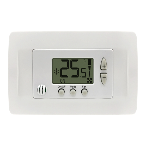
- Page 1 Room thermostat TATC/SUPER Owner’s manual and Technician settings Rev.03...
-
Page 2: Table Of Contents
Index 1. Owner’s Manual………………………………………………………………………………………….………… 3-5 1.1 Turning the unit On or Off ………………………………………………………………………………..……. 3 1.2 Adjusting the set-point temperature ……………………………………………………………………..…… 3 1.3 Selecting system mode …………………………………………………………………………………..……. 3 1.4 Selecting fan speed…………………………………………………………………………………………….. 3 1.5 Timer ………………………………………………………………………………………………………..…… 4 1.6 Locking the thermostats buttons…………………………………………………………………………..…… 4 2. -
Page 3: Owner's Manual
1. Owner’s Manual 1.1 Turning the unit On or Off Press the [On/Off] button to turn the unit On. The word “ON” will appear on display. Press the [On/Off] button again to turn the unit Off. Unit OFF Unit ON The word “OFF”... -
Page 4: Timer
1.5 Timer The timer will automatically turn the thermostat OFF after the selected number of hours. - Press and hold the [On/Off] button for 5 seconds – the hours will appear on display. - Use the [+] and [-] buttons to adjust the timer (range: 0-10 hours). - Press the [Mode] button or wait 30 seconds to return to normal mode. -
Page 5: Installation Instructions
2. Installation instructions The thermostat is designed for flush mounting in the room to be controlled. It should be located where the occupant can easily read the LCD display and use the controls. If the built in temperature sensor is being used the unit should be placed where the temperature represents the general room conditions. -
Page 6: Wiring Connections
3. Wiring connections High Medium Fan On/Off (2.6A) (DIP switch S3=OFF) Cool valve (0.5A) 4-Pipe One valve (0.5A) 2-Pipe (DIP switch (DIP switch 14 and 15 Heat valve (0.5A) S2=OFF) S2=ON) must be jumpered Condensing pump (works with “14”) (DIP switch S5=OFF) or Electric heater* (DIP switch S5=ON) Main supply 110~230VAC External sensor (option) (Technician parameter P8=1) -
Page 7: Dip Switch Configuration
4. DIP switch configuration IMPORTANT! Before making any changes in the DIP switch disconnect power from the unit. The DIP switch is located on the side of the thermostat, next to the Switch Switch T1,0 and IN1,0 terminals. Default End of line resistor connected End of line resistor not connected (last units in communication line) 2-Pipe... -
Page 8: Temperature Sensors Connection And Logic (T1 & T2)
5. Temperature sensors connection and logic (T1 & T2) Important – Use only an approved NTC 50K@25ºC external sensor with the following characteristics. N.TC. Sensor; Temperature ~ Resistance Characteristics Temp °F 45 Temp °C 7.2 10.0 12.8 15.6 18.3 21.1 23.9 26.7 29.4... -
Page 9: Technician Settings
6. Technician settings Enter technician settings Adjust the set point to 10°C and wait until display stops flashing. Press and hold the [Mode] button (7 sec.) to enter technician settings and parameters list. Use the [+] and [-] to switch between parameters: P01, P02, P03... Press the [Mode] button to select parameter and enter editing mode. - Page 10 6. Technician settings (cont.) P01. Offset for calibration of temperature reading P09. Input IN1,0 configuration Range: (-6)…(+6)°C, Default 0°C. “00” - Input IN1,0 not in use. “01” - Change over sensor P02. Set point temperature limit for cool For to 2-Pipe system – DIP switch S2=ON Range: 10...30°C, Default 10°C.
-
Page 11: P30 Beeper On / Off
6. Technician settings (cont.) P30 Beeper On / Off P91. Fan on demand configuration “00” - Beeper On (default). Fan on demand Fan continous “00” Cooling and Heating “01” - Beeper Off. “01” Heating Cooling “02” Cooling Heating P65. Fan proportional band value “03”... -
Page 12: Object List
Supported command: 0x03 = Read Holding Registers 0x06 = Write Single Register 0x10 = Write Multiple Registers 0x2B = Read Device Identification (Basic = 0x01, Regular = 0x02) 0x00 VendorName "Meitav-Tec Ltd" 0x03 VendorUrl "www.meitavtec.com" 0x01 ProductCode "22422601" 0x04 ProductName "TAT-C-SUPER"... - Page 13 7. Object list Reg./Addr. Name Range, Value, Units Default 22 / [0x015] LockRoomModuleMode 0 - Unlocked, 1 - Locked (RW) 23 / [0x016] LockRoomModuleOnOff 0 - Unlocked, 1 - Locked (RW) 24 / [0x017] LockRoomModuleFanSpeed 0 - Unlocked, 1 - Locked (RW) 25 / [0x018] LockRoomModuleSetPoint...
- Page 14 Notes - 14 -...
- Page 15 Notes - 15 -...
Need help?
Do you have a question about the TATC/SUPER and is the answer not in the manual?
Questions and answers