
Subscribe to Our Youtube Channel
Related Manuals for meitav-tec MTS/SUPER/CO2 series


Summary of Contents for meitav-tec MTS/SUPER/CO2 series
- Page 1 Touch Screen Thermostat MTSC/SUPER/CO2, MTSC24/SUPER/CO2 Series MTS/SUPER/CO2, MTS24/SUPER/CO2 Series Owner’s manual and technician settings Rev. 2.4...
-
Page 2: Table Of Contents
Index 1. Owner’s Manual ………………………………………………..3 1.1 Quick Guide …………………………………………………. 4 1.2 Turning the unit ON or OFF ……………………………….. 4 1.3 Adjusting the set-point temperature………………………...4 1.4 Switch between temperature scales………………………..4 1.5 Switching between System modes ……………………….. 5 1.6 Switching between Fan speeds……………………………..5 1.7 Fan on demand (Auto fan) ….…………………………….. -
Page 3: Owner's Manual
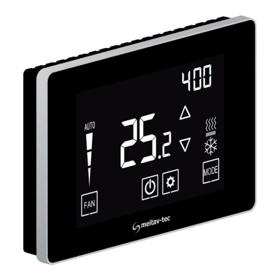
1. Owner’s manual 1.1 Quick Guide Temperature Ambient / System ON scale Set-point temperature display readings Fan speeds Set-point indication adjustment Modes indication Press to switch between Press to switch between Press to fan speeds: system modes: turn system ON or OFF *Auto High Med. -
Page 4: Turning The Unit On Or Off
1.2 Turning the unit ON or OFF Press the button to turn the unit ON – system mode and fan speed symbols will appear on display. Press again to turn the unit OFF – the symbols will disappear. Unit OFF Unit ON 1.3 Adjusting the set-point temperature While the thermostat is ON, press the... -
Page 5: Switching Between System Modes
1.5 Switching between system modes Press the button to switch between system modes: Cool Heat Auto mode only Notes: - During demand for cooling (cooling active), the will flash. - During demand for heating (heating active), the will flash. The selection of system modes may be disabled depending on system configuration. -
Page 6: Fan On Demand (Auto Fan)
1.7 Fan on demand (Auto fan) Press and hold the button to activate or deactivate fan on demand (Auto fan) function. Notes: - When activated, the fan will run with demand for cooling or heating. AUTO FAN active - The fan on demand function cannot be activated with “Fan only”... -
Page 7: Economy Mode Indications E1 - E5
1.10 Economy mode indications E1 – E6 Economy mode can be activated by triggering a window contact, door switch, key-tag or PIR sensor. When Economy mode is active, the thermostat will either turn off or use special economy set points for cooling and heating set by technician. -
Page 8: Freeze Protection
1.11 Freeze protection The Freeze protection feature will not allow the room temperature to drop below predefined cut-in temperature. Depending on which configuration the system is operating under (with or without Heat pump) this feature will force the system to operate in heat mode and activate the fan. -
Page 9: Fresh Air And Co2 Monitoring
1.12 Fresh air and CO monitoring The thermostat continuously monitors the ambient CO level using the built in CO sensor and compares the readings to the CO set-point. When the ambient CO level rises above the set-point, the fresh air damper will open to bring in fresh air. -
Page 10: Installation Instructions
2. Installation Instructions The MTS/SUPER/CO2 Thermostat designed for flush mounting in the room to be controlled. It should be located where the occupant can easily read the display and use the controls. If the built in temperature sensor is being used to measure room temperature, the panel should be placed where the temperature is representative of the general room conditions, away from cold or warm air draughts, radiant heat and direct sunlight. - Page 11 2. Installation Instructions (cont’) Installation procedure: 1. separate the front display from the back plastic cover by inserting a a small flat screwdriver into each of the three slots as shown in the picture and rotating it gently. 2. Remove the front display and keep it in a safe place. 3.
- Page 12 2. Installation Instructions (cont’) - 12 -...
-
Page 13: Wiring Configuration And Dip Switches
3. Wiring configuration and DIP Switches *External sensor / Deicing in cool sensor / Door switch / Key-Tag (options) **T2 change over sensor / T3 Deicing in cool sensor / See options on Remote OFF switch / next pages Remote economy switch / External PIR See options on next pages... - Page 14 3. Wiring configuration and DIP Switches – AC systems 1 2 3 4 5 6 7 8 1 2 3 4 5 6 1 2 3 4 5 6 7 8 1 2 3 4 5 6 1 2 3 4 5 6 7 8 1 2 3 4 5 6 1 2 3 4 5 6 7 8 1 2 3 4 5 6 Fan on/off: 24/110/230VAC, 3A max.
- Page 15 3. Wiring configuration and DIP Switches – AC systems 1 2 3 4 5 6 7 8 1 2 3 4 5 6 1 2 3 4 5 6 7 8 1 2 3 4 5 6 1 2 3 4 5 6 7 8 1 2 3 4 5 6 1 2 3 4 5 6 7 8 1 2 3 4 5 6 Fan on/off: 24/110/230VAC, 3A max.
- Page 16 3. Wiring configuration and DIP Switches – 2-Pipe FC systems 1 2 3 4 5 6 7 8 1 2 3 4 5 6 1 2 3 4 5 6 7 8 1 2 3 4 5 6 1 2 3 4 5 6 7 8 1 2 3 4 5 6 1 2 3 4 5 6 7 8 1 2 3 4 5 6 Fan on/off: 24/110/230VAC, 3A max.
- Page 17 3. Wiring configuration and DIP Switches – 4-Pipe FC systems 1 2 3 4 5 6 7 8 1 2 3 4 5 6 1 2 3 4 5 6 7 8 1 2 3 4 5 6 1 2 3 4 5 6 7 8 1 2 3 4 5 6 1 2 3 4 5 6 7 8 1 2 3 4 5 6 Fan on/off: 24/110/230VAC, 3A max.
- Page 18 3. Wiring configuration and DIP Switches – 4-Pipe FC systems 1 2 3 4 5 6 7 8 1 2 3 4 5 6 1 2 3 4 5 6 7 8 1 2 3 4 5 6 1 2 3 4 5 6 7 8 1 2 3 4 5 6 1 2 3 4 5 6 7 8 1 2 3 4 5 6 1 2 3 4 5 6 7 8 1 2 3 4 5 6 Fan on/off: 24/110/230VAC, 3A max.
-
Page 19: Technician Settings
4. Technician Settings Enter technician settings Adjust the set-point temperature to 10ºC. To enter technician settings, press and hold the button for 5 seconds. Use the button to advance to the next parameter. Use the button to return to return to the previous parameter. Press the button or wait 60 seconds to exit technician settings and return to normal display. - Page 20 4. Technician settings (cont’) P1 – Offset for temperature readings calibration Range: -6…+6°C / -9…+9°F. Default: 0°C / 0°F. P2 – Set point limit for cooling Range: 5…35°C / 41…90°F. Default: 5°C / 35°F. P3 – Set point limit for heating Range: 5…35°C / 41…95°F.
- Page 21 4. Technician settings (cont’) P7 – Lock the [+] and [-] buttons (Set buttons) “01” - [+] and [-] buttons Locked “00” - [+] and [-] buttons unlocked (default) P8 – Functionality of T1 terminals “00” - T1 terminals are not in use (default) “01”...
- Page 22 4. Technician settings (cont’) P10 – Polarity of remote switch contact on terminals IN,0 (P09 = “03” or “04”) “00” - Normally close (default) “01” - Normally open P11 – Time delay of remote switch contact on terminals IN,0 (P09 = “03” or “04”) Range: 0…999 seconds.
- Page 23 4. Technician settings (cont’) P16 – Enable/Disable Occupancy sensor “00” - Disable “01” - Enable (default) P17 – PIR (occupancy sensor) delay time before switching to unoccupied mode (ON delay) Range: 0…250 minutes, Default: 20 minutes P18 – Door switch/key-tag logic “00”...
- Page 24 4. Technician settings (cont’) P27 – Time on-delay between heating stages Range: 0…600 seconds Default: 5 seconds P28 – Time off-delay between heating stages Range: 0…600 seconds Default: 1 seconds P30 – Beeper ON or OFF “01” - Beeper ON (default) “00”...
- Page 25 4. Technician settings (cont’) P35 – Enable/Disable Freeze protection “01” - Enable freeze protection (default) “00” - Disable freeze protection P36 – Freeze protection cut-in set point Range: 8...15°C / 46…59°F Default: 8°C / 46°F P37 – Freeze protection cut-out set point Range: 10...17°C / 50…63°F Default: 10°C / 50°F P40 –...
- Page 26 4. Technician settings (cont’) P43 – Not in use P44 – Not in use P45 – Cool differential band (On/Off) Range: 0...5°C / 0…10°F Default: 1°C / 2°F P46 – Cool differential band offset Range: 0...5°C / 0…10°F Default: 0°C / 0°F P47 –...
- Page 27 4. Technician settings (cont’) P49 – Shift between Cool and Heat in Auto change over mode Range: 0...10°C / 0…20°F Default: 2°C / 4°F P50 – Shift between Cooling stages (AC only!) Range: 0...10°C / 0…20°F Default: 2°C / 4°F P51 –...
- Page 28 4. Technician settings (cont’) P55 – Heat proportional band (FC only!) Range: 2...10°C / 4…20°F Default: 2°C / 4°F P56 – Heat proportional low limit (FC only!) Range: 0...100% Default: 0% P57 – Heat proportional high limit (FC only!) Range: 0...100% Default: 100% P60 –...
- Page 29 4. Technician settings (cont’) P63 – Time on-delay between cooling stages (AC only!) Range: 0…600 seconds Default: 5 seconds P64 – Time off-delay between cooling stages (AC only!) Range: 0…600 seconds Default: 1 seconds P65 – Fan VFS proportional band in cooling Range: 2...10°C / 4…20°F Default: 2°C / 4°F P66 –...
- Page 30 4. Technician settings (cont’) P70 – Fan VFS Low speed percent in heating Range: 0...30% Default: 30% P71 – Fan VFS Medium speed percent in heating Range: 30...60% Default: 50% P72 – Fan VFS High speed percent in heating Range: 60...100% Default: 80% P74 –...
- Page 31 4. Technician settings (cont’) P76 – Fan VFS Low limit in cooling Range: 0...100% Default: 0% P77 – Fan VFS High limit in cooling Range: 0...100% Default: 100% P78 – Fan VFS Low limit in heating Range: 0...100% Default: 0% P79 –...
- Page 32 4. Technician settings (cont’) P86 – Deice in cool – cut-out temperature (AC only!) Range: -20...99°C Default: 8°C P87 – Deice in heat time (AC only!) Range: 120...420 Seconds Default: 300 Seconds P88 – Deice in heat break time (AC only!) Range: 600...1800 Seconds Default: 1500 Seconds P89 –...
- Page 33 4. Technician settings (cont’) P100 – Enable/Disable Screen dimming “00” - Disable “01” - Enable (default) P101 – Screen dimming delay Range: 0...99 minutes Default: 5 minutes P102 – Dimming percentage value Range: 1,5,10...90% Default: 10% P105 – Display brightness Range: 50...100% Default: 100% P114 –...
- Page 34 4. Technician settings (cont’) P117 – Heat PID Ki (FC only!) Range: 0...100% Default: 0% P118 – Cool PID Kd (FC only!) Range: 0...100% Default: 1% P119 – Heat PID Kd (FC only!) Range: 0...100% Default: 1% P122 – Cool proportional threshold time (update delay) (FC only!) Range: 0...100 sec.
- Page 35 4. Technician settings (cont’) P182 – CO Set point (activate fresh air damper) Range: 600…2000 ppm (display shows value divided by 10) Default: 750 ppm P183 – CO Band Range: 100…500 ppm (display shows value divided by 10) Default: 250 ppm P184 –...
-
Page 36: Mac Address (Mtsc Series Only)
5. MAC Address (MTSC Series only) Enter MAC Address settings Adjust the set-point temperature to 11ºC – the button will appear on display. To enter MAC Address settings, press and hold the button for 5 seconds. Use the buttons to change the MAC Address. Set “0”... - Page 37 Comments - 37 -...
- Page 38 Comments - 38 -...
- Page 39 Comments - 39 -...
- Page 40 www.meitavtec.com...
Need help?
Do you have a question about the MTS/SUPER/CO2 series and is the answer not in the manual?
Questions and answers