Table of Contents
Advertisement
Advertisement
Table of Contents

Related Manuals for meitav-tec MTSC


Summary of Contents for meitav-tec MTSC
- Page 1 Touch Screen Thermostat MTSC/SUPER/PPH Owner’s manual and technician settings...
- Page 2 - 2 -...
-
Page 3: Table Of Contents
1.6 Economy mode indications E1 – E5 ….………………….. 8 1.7 Freeze protection ………………………...…………………. 9 2. Installation Instructions……..………………………………..10 3. Wiring Configuration and DIP Switches…….……………..13 4. Technician Settings …….……………………………………..20 5. MAC Address (MTSC Series only) ……………...…………..36 - 3 -... -
Page 4: Owner's Manual
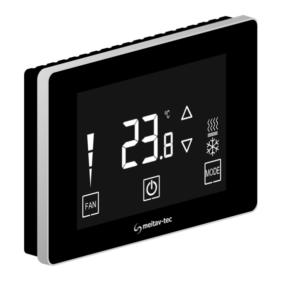
1. Owner’s manual 1.1 Quick Guide System ON Temperature Ambient / scale Set-point temperature Set-point display adjustment Fan speeds indication Press to switch between Press to fan speeds: turn system ON or OFF *Auto High Med. speed *In Auto speed, the active speed will appear System OFF - 4 -... -
Page 5: Turning The Unit On Or Off
1.2 Turning the unit ON or OFF Press the button to turn the unit ON – system mode and fan speed symbols will appear on display. Press again to turn the unit OFF – the symbols will disappear. Unit OFF Unit ON 1.3 Adjusting the set-point temperature While the thermostat is ON, press the... -
Page 6: Switching Between Fan Speeds
1.4 Switching between fan speeds Press the button to switch between fan speeds: Note: When Auto speed Is selected, the word “AUTO” Medium High Auto speed speed speed speed and the active fan speed will appear on display The selection of fan speeds may be disabled depending on system configuration. -
Page 7: Economy Mode Indications E1 - E5
1.10 Economy mode indications E1 – E6 Economy mode can be activated by triggering a window contact, door switch, key-tag or PIR sensor. When Economy mode is active, the thermostat will either turn off or use special economy set points for cooling and heating set by technician. -
Page 8: Freeze Protection
1.11 Freeze protection The Freeze protection feature will not allow the room temperature to drop below predefined cut-in temperature. Depending on which configuration the system is operating under (with or without Heat pump) this feature will force the system to operate in heat mode and activate the fan. -
Page 9: Installation Instructions
2. Installation Instructions The MTS/SUPER Thermostat designed for flush mounting in the room to be controlled. It should be located where the occupant can easily read the display and use the controls. If the built in temperature sensor is being used to measure room temperature, the panel should be placed where the temperature is representative of the general room conditions, away from cold or warm air draughts, radiant heat and direct sunlight. - Page 10 2. Installation Instructions (cont’) Installation procedure: 1. separate the front display from the back plastic cover by inserting a a small flat screwdriver into each of the three slots as shown in the picture and rotating it gently. 2. Remove the front display and keep it in a safe place. 3.
- Page 11 2. Installation Instructions (cont’) - 12 -...
-
Page 12: Wiring Configuration And Dip Switches
* For T1,0 functionality – refer to parameter P8 in the technician settings section. ** For IN1,0 functionality – refer to parameter P9 in the technician settings section. ***Communication protocol (MTSC Series only) is set by DIP Switch S1.8 as follows: S1.8 ON – BACnet S1.8 OFF –... - Page 13 Fan on/off: 24/110/230VAC, 3A max. Control - Heat elements, Heat pump, Compressors: 24/110/230VAC, 0.3A max. MTSC Series: SW1.8 = Communication Protocol: ON – BACnet, OFF – MODBUS SW1.4 = HP: ON – Heat pump active in cool, OFF – Heat pump active in heat HC: ON –...
- Page 14 3. Wiring configuration and DIP Switches – AC systems HC21 HP22 HP21 HC21 3 Speeds fan Fan VFS Fan VFS Fan VFS Fan high Fan high Fan high Fan high Fan medium Fan medium Fan medium Fan medium Fan low Fan low Fan low Fan low...
- Page 15 Fan VFS, PID valves: 0-10VDC. 5mA Not isolated Control - Heat elements, Cool/Heat valves, Compressors: 24/110/230VAC, 0.3A max. MTSC Series: SW1.8 = Communication Protocol: ON – BACnet, OFF – MODBUS SW1.4 = Enable/Disable 2 heating stage: ON – Enable, OFF – Disable SW1.5 = Chilled beam option (fan will not run with 1...
- Page 16 Fan VFS, PID valves: 0-10VDC. 5mA Not isolated Control - Heat elements, Cool/Heat valves, Compressors: 24/110/230VAC, 0.3A max. MTSC Series: SW1.8 = Communication Protocol: ON – BACnet, OFF – MODBUS SW1.4 = Enable/Disable 2 heating stage: ON – Enable, OFF – Disable SW1.5 = Chilled beam option (fan will not run with 1...
- Page 17 Fan VFS, PID valves: 0-10VDC. 5mA Not isolated Control - Heat elements, Cool/Heat valves, Compressors: 24/110/230VAC, 0.3A max. MTSC Series: SW1.8 = Communication Protocol: ON – BACnet, OFF – MODBUS SW1.4 = Enable/Disable 2 heating stage: ON – Enable, OFF – Disable SW1.5 = Chilled beam option (fan will not run with 1...
- Page 18 Control - Heat elements, Cool/Heat valves, Compressors: 24/110/230VAC, 0.3A max. Floor heating – the fan will not run with 1 stage heat MTSC Series: SW1.8 = Communication Protocol: ON – BACnet, OFF – MODBUS SW1.4 = Enable/Disable 2 heating stage: ON – Enable, OFF – Disable SW1.5 = Chilled beam option (fan will not run with 1...
-
Page 19: Technician Settings
4. Technician Settings Enter technician settings Adjust the set-point temperature to 10ºC. To enter technician settings, press the display three times within 5 seconds as shown below: Use the button to advance to the next parameter. Use the button to return to return to the previous parameter. Press the button or wait 60 seconds to exit technician settings and return to normal display. - Page 20 4. Technician settings (cont’) P1 – Offset for temperature readings calibration Range: -6…+6°C / -9…+9°F. Default: 0°C / 0°F. P2 – Set point limit for cooling Range: 5…35°C / 41…90°F. Default: 5°C / 35°F. P3 – Set point limit for heating Range: 5…35°C / 41…95°F.
- Page 21 4. Technician settings (cont’) P7 – Lock the [+] and [-] buttons (Set buttons) “01” - [+] and [-] buttons Locked “00” - [+] and [-] buttons unlocked (default) P8 – Functionality of T1 terminals “00” - T1 terminals are not in use (default) “01”...
- Page 22 4. Technician settings (cont’) P10 – Polarity of remote switch contact on terminals IN,0 (P09 = “03” or “04”) “00” - Normally close (default) “01” - Normally open P11 – Time delay of remote switch contact on terminals IN,0 (P09 = “03” or “04”) Range: 0…999 seconds.
- Page 23 4. Technician settings (cont’) P16 – Enable/Disable Occupancy sensor “00” - Disable “01” - Enable (default) P17 – PIR (occupancy sensor) delay time before switching to unoccupied mode (ON delay) Range: 0…250 minutes, Default: 20 minutes P18 – Door switch/key-tag logic “00”...
- Page 24 4. Technician settings (cont’) P27 – Time on-delay between heating stages Range: 0…600 seconds Default: 5 seconds P28 – Time off-delay between heating stages Range: 0…600 seconds Default: 1 seconds P30 – Beeper ON or OFF “01” - Beeper ON (default) “00”...
- Page 25 4. Technician settings (cont’) P35 – Enable/Disable Freeze protection “01” - Enable freeze protection (default) “00” - Disable freeze protection P36 – Freeze protection cut-in set point Range: 8...15°C / 46…59°F Default: 8°C / 46°F P37 – Freeze protection cut-out set point Range: 10...17°C / 50…63°F Default: 10°C / 50°F P40 –...
- Page 26 4. Technician settings (cont’) P43 – Not in use P44 – Not in use P45 – Cool differential band (On/Off) Range: 0...5°C / 0…10°F Default: 1°C / 2°F P46 – Cool differential band offset Range: 0...5°C / 0…10°F Default: 0°C / 0°F P47 –...
- Page 27 4. Technician settings (cont’) P49 – Shift between Cool and Heat in Auto change over mode Range: 0...10°C / 0…20°F Default: 2°C / 4°F P50 – Shift between Cooling stages (AC only!) Range: 0...10°C / 0…20°F Default: 2°C / 4°F P51 –...
- Page 28 4. Technician settings (cont’) P55 – Heat proportional band (FC only!) Range: 2...10°C / 4…20°F Default: 2°C / 4°F P56 – Heat proportional low limit (FC only!) Range: 0...100% Default: 0% P57 – Heat proportional high limit (FC only!) Range: 0...100% Default: 100% P60 –...
- Page 29 4. Technician settings (cont’) P63 – Time on-delay between cooling stages (AC only!) Range: 0…600 seconds Default: 5 seconds P64 – Time off-delay between cooling stages (AC only!) Range: 0…600 seconds Default: 1 seconds P65 – Fan VFS proportional band in cooling Range: 2...10°C / 4…20°F Default: 2°C / 4°F P66 –...
- Page 30 4. Technician settings (cont’) P70 – Fan VFS Low speed percent in heating Range: 0...30% Default: 30% P71 – Fan VFS Medium speed percent in heating Range: 30...60% Default: 50% P72 – Fan VFS High speed percent in heating Range: 60...100% Default: 80% P74 –...
- Page 31 4. Technician settings (cont’) P76 – Fan VFS Low limit in cooling Range: 0...100% Default: 0% P77 – Fan VFS High limit in cooling Range: 0...100% Default: 100% P78 – Fan VFS Low limit in heating Range: 0...100% Default: 0% P79 –...
- Page 32 4. Technician settings (cont’) P85 – Deice in cool – cut-in temperature (AC only!) Range: -20...99°C Default: 0°C P86 – Deice in cool – cut-out temperature (AC only!) Range: -20...99°C Default: 8°C P87 – Deice in heat time (AC only!) Range: 120...420 Seconds Default: 300 Seconds P88 –...
- Page 33 4. Technician settings (cont’) P99 – One or Two set points (for cool and for heat) (FC only!) “00” - One set point for cooling and heating (default) “01” - two set points – one for cool and one for heat P100 –...
- Page 34 4. Technician settings (cont’) P116 – Cool PID Ki (FC only!) Range: 0...100% Default: 0% P117 – Heat PID Ki (FC only!) Range: 0...100% Default: 0% P118 – Cool PID Kd (FC only!) Range: 0...100% Default: 1% P119 – Heat PID Kd (FC only!) Range: 0...100% Default: 1% P198 –...
- Page 35 4. Technician settings (cont’) P136 – Time initialization of heat valve Range: 60...500 seconds Default: 210 seconds P137 – T2 indication for cold water Range: 7...35°C Default: 30°C P138 – T2 indication for hot water Range: 20...45°C Default: 32°C P200 – Restore defaults Press the button to restore defaults Press the...
-
Page 36: Mac Address (Mtsc Series Only)
5. MAC Address (MTSC Series only) Enter MAC Address settings Adjust the set-point temperature to 11ºC – the button will appear on display. To enter MAC Address settings, press and hold the button for 5 seconds. Use the buttons to change the MAC Address. - Page 37 Comments - 37 -...
- Page 38 Comments - 38 -...
- Page 39 Comments - 39 -...
- Page 40 www.meitavtec.com...
Need help?
Do you have a question about the MTSC and is the answer not in the manual?
Questions and answers