Table of Contents
Advertisement
Quick Links
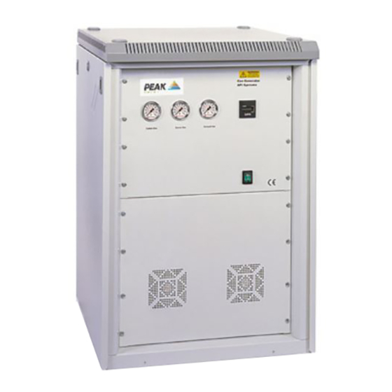
NM20ZA
Service Manual – Revision 13
High Purity Nitrogen Generator
Email Technical Support:
NM20ZA Service Manual Rev 14
Service Manual
NM20ZA 230Vac
Gas Station
(19" Rack System)
Peak Scientific Instruments Ltd
Fountain Crescent
Inchinnan Business Park
Inchinnan
Renfrew PA4 9RE
Scotland
Tel (Europe) +44 (0) 141 812 8100
Tel (USA) +1 866 647 1649 (sales)
Tel (USA) +1 866 732 5427 (tech support)
Fax (Europe) +44 (0) 141 812 8200
Email Sales:
info@peakscientific.com
support@peakscientific.com
Or on the web @
www.peakscientific.com
1
Advertisement
Table of Contents

Related Manuals for Peak Scientific NM20ZA


Summary of Contents for Peak Scientific NM20ZA
- Page 1 Tel (USA) +1 866 647 1649 (sales) Tel (USA) +1 866 732 5427 (tech support) Fax (Europe) +44 (0) 141 812 8200 Email Sales: info@peakscientific.com Email Technical Support: support@peakscientific.com Or on the web @ www.peakscientific.com NM20ZA Service Manual Rev 14...
-
Page 2: Document Change History
Parts List Updated to include new SAP part Numbers 29-08-03 Parts List Updated to include new SAP part Numbers 22-06-04 Updated 20/12/04 Shipping Weight updated 17/03/05 Flow settings updated 29/03/05 New Part No. for Relief Valve 24/08/05 NM20ZA Service Manual Rev 14... -
Page 3: Warranty Statement
These instructions must be read thoroughly and understood before installation and operation of your Peak Nitrogen Generator. Use of the Generator in a manner not specified by Peak Scientific Inst. MAY impair the SAFETY provided by the equipment. When handling, operating or carrying out any maintenance, personnel must employ safe engineering practices and observe all relevant local health and safety requirements and regulations. -
Page 4: Table Of Contents
Technical Specification Connection to the Instrument Generator Controls Electrical Connection Operator Training START-UP Sequence Pressure & Flow Settings Principal of Operation Routine Maintenance Electrical Diagram – WD-NM20/30 Pneumatic Diagram – PD-NM20ZA Parts List Maintenance Log NM20ZA Service Manual Rev 14... -
Page 5: Introduction
Unpacking and Installation. Although Peak Scientific takes every precaution with safe transit and packaging, it is advisable to fully inspect the unit for any sign of transit damage. -
Page 6: Generator Environment
75mm (3”) should be maintained down both sides and across the top of the unit. Please refer to the drawing below for the general dimensions of the generator. MAXIMUM AMBIENT CONDITIONS: - ° ° ° ° C (dry bulb) 70%RH (Max) General Dimensions NM20ZA Service Manual Rev 14... -
Page 7: Technical Specification
Control Circuit Breaker 2.0 Amps Electrical Connection Single Phase Power Cord General Dimensions W x D x H 60 x 67 x 94 (inches) (24 x 27 x 37) Weight 112.5 (lbs) (248) Shipping Weight (lbs) (372) NM20ZA Service Manual Rev 14... -
Page 8: Connection To The Instrument
2- off 1/4" x 1/8" Comp. Fitting (02-1000) with 1/8" Tubing (00-1262) Power Cord 1 off 1/4" Double Nipple (02-4399) (04-1038-EU) 1 off 1/8" x 1/4" Compression Fitting (02-1009) (04-1029-US) with 1/4" Tubing (00-1266) (04-1030-UK) 230Vac NM20ZA Service Manual Rev 14... -
Page 9: Generator Controls
Curtain Gas Outlet. Source Gas Outlet. Curtain Gas Source Gas Exhaust Gas Elapsed Time Meter. Exhaust Gas Outlet. CURTAIN SOURCE EXHAUST Serial Plate. On/Off Switch. Mains Power IEC. Socket. Drain Connection. SUPPLY DRAIN Air Inlet Fans. NM20ZA Service Manual Rev 14... -
Page 10: Electrical Connection
Connect the generator to a single-phase supply using the power cord provided. Operator Training The NM20ZA Laboratory Gas Generator is designed specifically to minimize operator involvement. Given that the generator is installed as described in earlier sections and is serviced in accordance with the following maintenance recommendations then it should simply be a matter of turning the generator on. -
Page 11: Start-Up Sequence
The above settings should allow the PSI Gas Station to be operated with all standard configurations for the Api range of LC/MS/MS instruments. Should the above settings not provide sufficient flow or pressure for your application please contact the factory for assistance. NM20ZA Service Manual Rev 14... -
Page 12: Principal Of Operation
Service Manual – Revision 13 Principal of Operation. Peak Scientific Instruments NM20ZA Generators utilize two different types of air preparation membranes to produce the required Gas outputs. The Nitrogen side of the generator employs “Hollow Fibre Membrane” Technology to efficiently separate Nitrogen from other gases present in ambient air. An overview of this process can be seen below. -
Page 13: Routine Maintenance
Compressor Units (the lesser of) Every 6000 hours or 18- months. Service kits are available for all routine maintenance; please contact the factory for further details. FAILURE TO FOLLOW THE PRESCRIBED MAINTENANCE PLAN WILL INVALIDATE THE PRODUCT WARRANTY NM20ZA Service Manual Rev 14... - Page 14 NOTE: - Compressed gas systems are dangerous and attempting to remove or open any component whilst under pressure could result in injury or death. Remove the 8-off fixing screws securing the Lower Front Panel and push forward the sliding tray as shown. NM20ZA Service Manual Rev 14...
- Page 15 Once the filters are replaced, carefully slide the tray back into place ensuring that the power cables and silver braided hoses are clear of all obstructions. Re-fit the 8-off screws ensuring they are properly tightened to prevent vibration. NM20ZA Service Manual Rev 14...
- Page 16 NOTE: - Compressed gas systems are dangerous and attempting to remove or open any component whilst under pressure could result in injury or death. Un-lock and remove the right side panel. Continued > Next Page NM20ZA Service Manual Rev 14...
- Page 17 Clean the bowl with a damp cloth prior to re-assembly. Re- Filter Element (02-4335) assembly is the reverse procedure. Ensure the drain pipe is secure in the fitting at the Coalescing bottom of the bowl Filter NM20ZA Service Manual Rev 14...
-
Page 18: Compressor Maintenance
NOTE: - Compressed gas systems are dangerous and attempting to remove or open any component whilst under pressure could result in injury or death. Remove the 8-off fixing screws securing the Lower Front Panel and pull out the sliding tray as shown. NM20ZA Service Manual Rev 14... - Page 19 Disconnect the two braided hoses to the compressors Disconnect the two grey compressor plugs (ensuring the metal clip has been loosened) and the white fan plug. Disconnect the two black plugs from the front panel fans. NM20ZA Service Manual Rev 14...
- Page 20 Remove the four fixing screws from the sides of the compressor tray. The tray assembly can now be lifted clear. Re-assembly is the reverse procedure. After re-fitting switch the generator on and check for leaks. NM20ZA Service Manual Rev 14...
- Page 21 L N L N E Un-Loading Mains Socket Pin Valves Supply Configuration Small Compressor (Q2) Large Compressor (Q1) Connector Connector Plug Connector Plug Connector Plug Plug Rear Cooling Fans Front Cooling Fans Beko Autodrain (If Fitted) NM20ZA Service Manual Rev 14...
-
Page 22: Pneumatic Diagram - Pd-Nm20Za
16. Zero Air Receiver ELECTRICAL PANEL ASSEMBY 7. Solenoid Valves 17. Pressure Flow Controller FRONT PANEL 8. Exhaust Silencer 18. Output Ports 9. Pressure Switches 19. Drain Port Curtain Source Exhaust 10. DryPoint Membrane NM20ZA Pneumatic Diagram NM20ZA Service Manual Rev 14... -
Page 23: Parts List
Output Regulator Assembly 08-4484 Pressure / Flow Controller 08-4486 Preventative Maintenance Kit, Svc Flow Meters peak Gas Gen 08-5100 WP085100 Gauge Pressure 100mm 0-11 BAR for Service Engineers 02-4593 WP024593 CD, NM20ZA SERVICE INFO PEAK NM20ZAV11 WPNM20ZAV11 NM20ZA Service Manual Rev 14... - Page 24 NM20ZA Service Manual – Revision 13 Notes: NM20ZA Service Manual Rev 14...
-
Page 25: Maintenance Log
NM20ZA Service Manual – Revision 13 Maintenance Log Model- NM20ZA. Serial number : Work Done Remarks Date Name NM20ZA Service Manual Rev 14...
Need help?
Do you have a question about the NM20ZA and is the answer not in the manual?
Questions and answers