Table of Contents
Advertisement
Quick Links
Last Update: November 2023
Version: V2
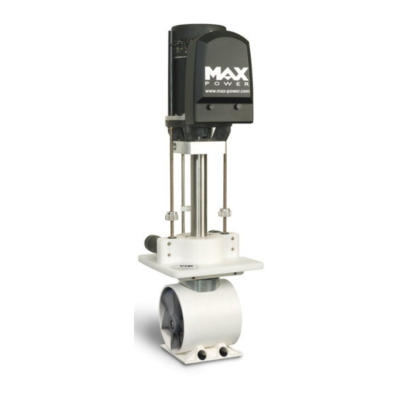
VERTICAL RETRACTABLE THRUSTER
VIP 150 48V ELECTRIC
INSTALLATION
OPERATION
MAINTENANCE
Serial Number:.............................
Date of Installation:......................
THIS MANUAL MUST BE KEPT ON BOARD AT ALL TIMES
Via Philips 5, 20900, Monza, Italy
Tel.:+39 039 200 1973-936
Fax: +39 039 2004299
www.max-power.com
Advertisement
Table of Contents

Related Manuals for MAX power VIP 150 48V ELECTRIC


Summary of Contents for MAX power VIP 150 48V ELECTRIC
- Page 1 Last Update: November 2023 Version: V2 VERTICAL RETRACTABLE THRUSTER VIP 150 48V ELECTRIC INSTALLATION OPERATION MAINTENANCE Serial Number:......Date of Installation:...... THIS MANUAL MUST BE KEPT ON BOARD AT ALL TIMES Via Philips 5, 20900, Monza, Italy Tel.:+39 039 200 1973-936 Fax: +39 039 2004299 www.max-power.com...
-
Page 2: Table Of Contents
VIP 150 48V with 24V Electronic Controller 2023 BEFORE STARTING THE INSTALLATION, IT IS RECOMMENDED TO CAREFULLY READ THE FOLLOWING MANUAL. TABLE OF CONTENTS mber Description Page POSITIONING DETERMINE THE LOCATION OF THE AUXILIARY EQUIPMENT MECHANICAL INSTALLATION MOUNTINING BASE INSTALLATION 3.1. -
Page 3: Positioning
48V battery bank and be easily accessible THRUSTER MUST and clearly marked The automatic battery isolator (24V command), as by Max Power, SUPPLIED SHOULD installed in the positive ply cable, as close as possible to the battery bank, THRUSTER... -
Page 4: Mechanical Installation
(Please refer to “B Drawing” at back of this UILD DOCUMENT , either a reinforced G.R.P. base or a 5086 MAX POWER can SUPPLY MOUNTING flange. These bases save considerable shipyard time while ALUMINUM ALLOY MOUNTING solid and precise installation. - Page 5 VIP 150 48V with 24V Electronic Controller 2023 The VIP plate sideways PUSHES THRUST Mounting against the inside of the base MOUNTING Base when ng. This means that one RUNNI MUST Flange ( a ) totally lower the and check the ounting UNIT following:...
-
Page 6: Construction Of Hull Opening & Closing Plate
VIP 150 48V with 24V Electronic Controller 2023 CONSTRUCTION OF HULL OPENING & CLOSING PLATE: The opening made for the in the is closed by a plate, which can be made THRUSTER HULL from the section, or specially fabricated. CUTOUT HULL a) The closing plate d fit into a 15 –... -
Page 7: Final Adjustment Of The Closing Plate
VIP 150 48V with 24V Electronic Controller 2023 FINAL ADJUSTMENT OF THE CLOSING PLATE: Once the is permanently bolted onto the base, reinstall the closing THRUSTER MOUNTING plate to do the final adj stments. "Up" Position Detector Proximity ( b ) Switches ( d ) ( c ) -
Page 8: Electrical Installation
VIP 150 48V with 24V Electronic Controller 2023 When finished with the final , fix the alloy plate bracket by bolting ADJUSTMENTS THROUGH the GRP in addition to the cable clamps. TURBINE IMPORTANT: Please keep in mind that the power motors is not ... -
Page 9: Power Cable Selection
THUS electric motor that is protected by the the power cables THRUSTER FUSE SUPPLYING motor. THRUSTER The Max Power fuses have been selected for their operation cycle and characteristics, CURRENT CONSEQUENTLY lower rated than traditionally rated may be MUCH FUSE fitted. -
Page 10: Battery Requirements
RUSTER SHOULD marked. An electrical battery isolator, as s pplied by Max Power, ld also be installed in the SHOU positive cable, as close as possible to the battery bank, in order to benefit... -
Page 11: Control Circuit
“electronic control box” can only be THRUSTERS UIPPED USED with Max Power’s range of control panels as shown in this MANUAL The VIP electronic control box must be supplied by 24V stable power. The installer protect the positive... -
Page 12: Control Panel And Thruster Control Box Functions
VIP 150 48V with 24V Electronic Controller 2023 CONTROL PANEL AND THRUSTER CONTROL BOX FUNCTIONS: "On/Off" Push-button: Black with Green "On" LED. Control Panel: To switch "ON" or "OFF" down PUSH the black , while PUSH BUTTON PUSHING Joystick joystick to the right for one second. To "Lower"... - Page 13 VIP 150 48V with 24V Electronic Controller 2023 4.7.3 T "Left" or "Right": HRUSTING a) Use joystick to either left or right. THRUST b) Please note that it is only possible to left or right when is detected to be THRUST THRUSTER down.
-
Page 14: Tests & Checks
VIP 150 48V with 24V Electronic Controller 2023 TESTS and CHECKS BEFORE LAUNCHING: a) Raise and lower THRUSTER b) Check that the closing plate firmly. HULL SHUTS c) Confirm that all bolts have been ently tightened, especially the base bolts. SUFFICI d) Correct the of the position detectors, if needed. -
Page 15: Basic Maintenance
If drive leg oil seals are to be worn, replace drive leg with exchange FOUND UNIT g) Always keep the propellers and clean. TUNNEL h) Please contact closest Max Power for local service points. YOUR DISTRIBUTOR... -
Page 16: Bronze Drive Leg
Always keep the propellers and clean. TUNNEL g) Do not paint the anode. h) Please contact closest Max Power for local service points. YOUR DISTRIBUTOR GENERAL: a) R check that the power cable connections are tightened correctly and that they... -
Page 17: Principal Dimensions
286mm 955mm Stroke 243mm Stroke 243mm Hull parts Total Unit Weight: 50kg UNLESS TITLE REVISION PART NO. OTHERWISE Principal Dimensions VIP 150 48V SPECIFIED CADD REF. MATERIAL SCALE Max Power DRAWN CHECK RELEASE HEAT TREAT & FINISH DATE DATE DATE... -
Page 18: Build Drawings
216mm 216mm 10mm Gussets 270mm 240mm Sikaflex Gasket Construction Point 216mm 10mm Other Hull Shape Other Hull Shape TITLE: Build Drawing PRODUCT REFERENCE: VIP 150 48V DRAWN: REVISION: DATE: 2022... -
Page 19: 8.3 Wiring Diagram
VIP 150 48V with 24V Electronic Controller 2023 8.3 WIRING DIAGRAM:... -
Page 20: Electronic Control Box Connections
NOTES: The installer must protect the positive supply cable by means of a fuse (slow b low). The size of these supply wires (min. 2,5mm² with Imax = 15 A) depends on the length of the cable run and the voltage drop in these cables should not exceed 5% of the nominal battery voltage. A double pole isolator/breaker clearly marked "Thruster " should be installed on the yachts main equipment switchboard in order to isolate the control circuit and/or power circuit, when thruster is not in use. This isolator/breaker should ide ally be supplied from an independent ... -
Page 21: 8.5 Wiring Of Additional Control Panels For Vip Thrusters
VIP 150 48V with 24V Electronic Controller 2023 8.5 WIRING OF ADDITIONAL CONTROL PANELS FOR VIP THRUSTERS: PARTS LISTS & DIAGRAMS: PARTS LIST & DIAGRAM: A No DESCRIPTION Qty CODE 1 Motor Relay Cover 1 313735 1 2 Electric Thruster Motor 48V 636662 1 3 Complete Thruster Relay 24V ... -
Page 22: Parts Diagram: B
VIP 150 48V with 24V Electronic Controller 2023 10 – Heat sensor TITLE: Parts List: A PRODUCT REFERENCE: VIP 150, Electric DRAWN: REVISION: DATE: PARTS DIAGRAM: B... - Page 23 REVISION PART NO. 3RD ANGLE PROJECTION UNLESS TITLE REVISION PART NO. OTHERWISE Parts List: B VIP 150, 48V. SPECIFIED CADD REF. MATERIAL SCALE Max Power DRAWN CHECK RELEASE HEAT TREAT & FINISH POWER DATE DATE DATE 03/05/01...
- Page 24 No DESCRIPTION: Qty CODE 16 Composite Leg 1 35035 22 Leg Bolts 2 634204 25 Propeller 2 636576 26 Propeller G Screw 2 634518 27 Propeller Pin DIN7 5x48 A4 2 312053 48 Nyloc N 8mm 1 635604 49 Machine Washer 1 635628 50 Coter Pin 1 635627 51 Water Gland Retaining Ring 1 ...
- Page 25 PURPOSE DOCUMENT by the End User from Max Power or its approved network of resellers. This PRODUCTS PURCHASED will adhere to the following format: DOCUMENT 10.1 DEFINITIONS Repair N –...
-
Page 26: Warranty Coverage
PRIOR TO CONTACTING THE DEALER/INSTALLER Contact yo dealer/installer to report the problem. a) If do not know who this is, contact the nearest Max Power distri BUTOR b) If are in foreign waters, please contact the nearest Max Power distri... - Page 27 VIP 150 48V with 24V Electronic Controller 2023 CYPRUS CYPRUS OCEAN MARINE EQUIPMENT LTD TUTI MARE TRADING Limassol Limassol Tel: + 357 53 69 731 Tel: + 357 25 431 313 Fax: + 357 53 52 976 Fax: + 357 25 431 300 Email: oceanm@spidernet.com.cy Email: tutimare@cytanet.com.cy...
-
Page 28: Distributer Contact List
VIP 150 48V with 24V Electronic Controller 2023 NORWAY SWEDEN PROGRESS INGENIORFIRMA AS PLASTIMO NORDIC Kjeisaas Henan Tel: + 47 22 02 79 00 Tel: + 46 304 360 60 Fax: + 47 22 02 79 01 Fax: + 46 304 307 43 Email: thomas@progressing.no Email: mikael.andersson@navimo.se... -
Page 29: Warranty Form
WARRANTY FORM VERY IMPORTANT Please complete this form and fax a COPY to Max Power with a copy of the installation invoice or the invoice of the yacht/boat in order for the warranty to come into effect. To Be Completed by Owner: Name of Owner:…………………………….
Need help?
Do you have a question about the VIP 150 48V ELECTRIC and is the answer not in the manual?
Questions and answers