Table of Contents
Advertisement
Quick Links
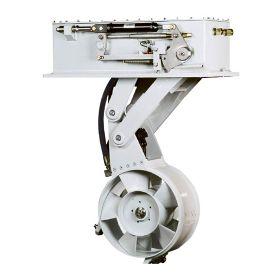
MAX POWER RETRACT R450
A copy of this manual must remain
on board for consultation.
- 1
INSTALLATION MANUAL RETRACT R 450
F
O
R
F
O
R
B
U
I
L
T
B
Y
B
U
I
L
T
B
Y
_
_
_
_
D
E
L
I
V
E
R
E
D
D
E
L
I
V
E
R
E
D
_
_
_
_
_
_
_
_
_
_
_
_
_
_
_
_
_
_
_
_
_
_
_
_
_
_
_
_
_
_
_
_
_
_
_
_
_
_
_
_
_
_
_
_
_
_
_
_
Last update: November 2023
Advertisement
Table of Contents

Related Manuals for MAX power R450/50


Summary of Contents for MAX power R450/50
- Page 1 MAX POWER RETRACT R450 A copy of this manual must remain on board for consultation. INSTALLATION MANUAL RETRACT R 450 Last update: November 2023...
-
Page 2: Troubleshooting Guide
MAX POWER INTRODUCTION CONTACTING MAX POWER IMPORTANT GENERAL INFORMATION CHECK LIST FOR THE PROJECT MANAGER DETERMINING BEST EQUIPMENT LOCATION OF THE RETRACT THRUSTER UNIT OF THE AUXILIARY EQUIPMENT INSTALLATION PROCEDURES CONSTRUCTION OF THE MOUNTING BASE CONSTRUCTION OF HULL OPENING & CLOSING PLATE... - Page 3 MAX POWER INTRODUCTION AFTER SALES SERVICE ADDRESS: MAX POWER Via Philips 5, 20900 Monza, Italy TEL : + 39 039 200 1973-936 FAX : + 39 039 2004299 RETRACT SERIAL N° . R4 _ _ . _ . _ _...
- Page 4 IMPORTANT: All Test readings must be filled out on the form provided and sent to Max Power by fax no later than one week after the water tests have been completed so that the Max Power standard warranty is correctly validated. This form is attached at the end of this manual.
-
Page 5: Guide Blocks
INSTALLATION OF THE RETRACT UNIT CONSTRUCTION OF THE MOUNTING BASE MAX POWER can supply as an option, a G.R.P. laminated mounting base, aluminium alloy machined mounting-flange. These options allow you to save considerable installation time, and assure precise installation. -
Page 6: Construction Of Hull Opening & Closing Plate
MAX POWER METAL HULLS: The mounting base may be constructed with the hull or prefabricated, and then welded onto the hull later. NOTE: In both hull cases, the top surface of the mounting base ( the flange) must be given particular attention and machined perfectly flat in order to accept the «... - Page 7 The nylon washers avoid stainless steel contact with the aluminum case. The nuts should be NYLOCK self-locking type. The 4 lifting lugs provided by MAX POWER, should be put in a small plastic bag, along with the hydraulic pipe plugs, for storage and future use by the ships crew.
- Page 8 A RETRACT R450/40 Can take up to 110 LPM of hydraulic flow this will causes on a normal installation approximately 210 bar pressure at the thrusters inlet ports. A RETRACT R450/50 Can take up to 170 LPM of hydraulic flow this will causes on a normal installation approximately 170 bar pressure at the thrusters inlet ports.
- Page 9 All the hydraulic power equipment, such as the piping, reservoir, pump, directional valve, etc. should be installed in compliance with the usual rules of accessibility to enable periodic checks and maintenance. MAX POWER recommends the use of ISO GRADE 15 to 32 hydraulic oil for the power circuit. PRESSURE PIPING...
-
Page 10: Directional Control Valve
The control box command’s the up down unit and hydraulic power spool valves in the correct sequence with correct timing. (Sequence chart with diagrams) There is scope for modifying sequence timing in this box but consult MAX POWER FIRST! (See diagram N° 8) All Retract equipment is connected to this box (See diagram N°... -
Page 11: Before Launching
MAX POWER recommends the use of ISO GRADE 15 to 32 hydraulic oils for the power circuit. This mineral oil has already been used by Max Power during the run in tests and consequently the RETRACT motor and piping are already filled with this kind off oil. -
Page 12: Operation And Use
MAX POWER Warning: All hydraulic systems develop very high pressures. Failure of piping, connections etc that have been improperly installed will most likely happen on start up. Stay clear of these components. Wear eye protection, and be aware that high- pressure oil can cause major skin damage. - Page 13 Intermittently: 5 min at 20°C Continuous operation: For longer service periods, Max Power recommends an optional heat exchanger and water pump installation to provide extra oil cooling. TROUBLESHOOTING GUIDE PROBLEM : Thrust stops almost immediately after it has been applied. The alarm buzzer comes on and the green light turns off.
- Page 14 MAX POWER The RETRACT R450 is equipped with a manual override device, which can be used for lowering the RETRACT turbine from the UP to the DOWN position. IMPORTANT never leave the Manuel override screw unscrewed, while using the hydraulic up down unit this would result in very serious damage.
- Page 15 MAX POWER 9. Check the entire hydraulic system hoses and connections for possible chaffing and leaks. 10. Every two years, drain the entire hydraulic oil system. Properly clean or replace filters in order to protect the hydraulic circuit in general.
- Page 16 MAX POWER PROJECT MANAGER’S TEST RESULTS FORM To be filled out and faxed to MAX POWER - 16 INSTALLATION MANUAL RETRACT R 450...
- Page 17 MAX POWER TEST RESULT FORM (part 1) This form must be filled out and send to MAX POWER via email within a week after launching, in order for the standard Max Power warranty to be valid: Date : ………………………… REFERENCE : S _ _ .R4_ _ . _ _ _ _ 11.
- Page 18 MAX POWER When all the tests have been completed as per the manual, please record the following measurements where applicable. With the engine(s) running, thruster in the down position, but not running: Record the voltage at the remote control box: …………………...
- Page 19 A minimum immersion depth of one full turbine diameter should be respected with the thruster positioned, as forward as possible for bow installation or as aft as possible for stern installation. The thruster must be parallel with the bottom of the hull not to the water line!
- Page 20 MAX POWER Allow 200 Mounting base as supied by MAX POWER Hull parts manufactured by ship yard Principal dimentions Optional flotation foam to reduce loss of boyancy Retract Thruster Construction point ( Never changes nomater the hull shape ) Flexable water seals...
- Page 21 MAX POWER Thruster mounted to high Will cause low performance and more loss of buoyancy. Thruster mounted correctly Thruster mounted to low Will cause contact between Hull plate and thrusters turbine. This will seriously damage turbine. - 21 INSTALLATION MANUAL RETRACT R 450...
- Page 22 MAX POWER Closing adjustments (lock) This is a correctly locked thruster Maximum gap 0.01mm Closing adjustments (closing plate) Fig 1 Caution this situation would cause damage to the turbine while at sea . In this situation there is still up wards movement possible...
- Page 23 Thruster up and locked Gas spring on other side pushing Thruster down Gas spring on other side pushing Ram at rest Ram pulling Ram spring Lifting arm Bolt Bolt spring Bolt spring Thruster unlocking Gas spring on other side pushing Ram spring compresed Ram pulling Bolt puled out of lifting arms lock...
- Page 24 MAX POWER Manuel operation To use manual lowering screw Disconnect hydraulic connections on ram A&B (or energize up down unit control valve) Turn manual lowering screw clockwise Place security bolt (A) in thread hole (B) before working on the unit.
- Page 25 Control system wiring diagram R450 10 x 1 mm² Yachts main equipment breaker bord Control panel(s) N° 1 2 12 13 14 functions on 12v OF F OF F OF F OF F OF F OF F OF F OF F OF F OF F OF F...
- Page 26 MAX POWER POWER 47nk400 47nk400 47nk400 47nk400 47nk400 47nk400 47nk400 47nk400 47nk400 47nk400 47nk400 Switch bar C10 The more bars are on the longer the time delay before port 31&32 energize 47nk400 47nk400 47nk400 47nk400 47nk400 12 13 14 15 16 17...
- Page 27 MAX POWER R450 Control box wiring (2012 – 2021) - + + + + + + + + + - + - + + - + + + - + + 2 12 13 14 15 16 17 18 19...
- Page 28 MAX POWER R450 Control box wiring (after 2022) Service & closing plate fixations At each out haul Remove both propellers using a hub extractor Replace all anodes ( C ) Hull plate bracket to be made in such a way as no contact is...
- Page 29 Service Centers 1) Definitions Authorized Repair Number – The number given by Max Power on reporting a fault with your thruster Dealer – An authorized Max Power sales centre End User – The boat supplied with supplied equipment and the owner thereof Installer – The authorized centre responsible for the installation of your thruster Manufacturer –...
-
Page 30: Max Power
MAX POWER 3) Warranty Registration Register your purchase now to receive free extended warranty coverage of 1 year (total 3 years). This can be done using one of the following methods (NB. proof of purchase must be included to establish that equipment is still under warranty): The quickest and easiest method to register your warranty is to send the attached installation check list and warranty registration to the Manufacturer website: https://www.max-power.com/warranty... - Page 31 Dealer/Installer will come to site to decipher the cause of the fault If the cause of fault is due to a manufacturing problem the dealer will contact Max Power to receive Repair Authorization Number. If the problem is due to an installation error please contact your installer.
Need help?
Do you have a question about the R450/50 and is the answer not in the manual?
Questions and answers