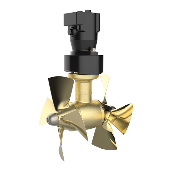
Table of Contents
Advertisement
Quick Links
INSTALATION OPERATION MAINTENANCE
Serial N° : ..........................................................................................................................
Date of Installation : ......................................................................................
IT IS IMPORTANT TO KEEP THIS MANUAL ON BOARD!
INSTALLATION MANUAL CT550
CT550 MANUAL
Last update: June 2020
Address :5, Via Philips Str, 20900 Monza (MI),
Italy Tel: +39 039 2001973 Fax: +39 039 2004299
1
Advertisement
Table of Contents

Summary of Contents for MAX power CT550
- Page 1 INSTALLATION MANUAL CT550 CT550 MANUAL INSTALATION OPERATION MAINTENANCE Last update: June 2020 Serial N° : .......................... Date of Installation : ………………………………………………………………………….. IT IS IMPORTANT TO KEEP THIS MANUAL ON BOARD! Address :5, Via Philips Str, 20900 Monza (MI), Italy Tel: +39 039 2001973 Fax: +39 039 2004299...
-
Page 2: Table Of Contents
PROPELLERS ..................................6 PROTECTION GRILLS ................................ 6 HYDRAULIC (general remarks) ............................7 HYDRAULIC SPECIFICATIONS............................8 MAINTENANCE ................................8 CT550 PART LIST ............................... 10 WIRING DIAGRAM ..............................12 HYDRAULIC DIAGRAM ............................... 13 POSITIONING AND MESURMENTS ..........................14 PROPELLER ASSEMBLY .............................. 15 MAIN DIMENSIONS .............................. - Page 3 INSTALLATION MANUAL CT550 Your thruster is a high quality technical product and should be treated as such. The employment of qualified marine personnel, with experience in bow thruster installation, is strongly advised. Where possible, the boat manufacturer’s architects, design departments and/or shipyards should be consulted, prior to installation taking place.
-
Page 4: General Installation Guidlines
INSTALLATION MANUAL CT550 1. GENERAL INSTALLATION GUIDLINES Decide on the best location for the thruster. (See drawing: “Positioning & Measurements” at back of manual). The tunnel must be as low as possible and as far forward as possible. The propellers must not protrude beyond the hull line. -
Page 5: Propeller Drive Leg & Motor Support
INSTALLATION MANUAL CT550 Fit the tunnel and mark the areas to be fibre-glassed. Sand these areas inside and out. In certain installations it is preferable to drill the position of the thruster support before the installation of the tunnel. Refit the tunnel. Apply reinforced fibreglass filler to all areas, taking care that you fill the gap between hull and tunnel. -
Page 6: The Hydraulic Motor
INSTALLATION MANUAL CT550 4. THE HYDRAULIC MOTOR Insert the lower drive coupling onto the leg drive shaft (lightly grease the shaft before doing this). Then position the motor and tighten the 4 x 12 mm to 80Nm. IMPORTANT: Please note that the above coupling might need to be adjusted if any other tunnel than a Max Power tunnel (thickness 12-14mm) is used. -
Page 7: Hydraulic (General Remarks)
INSTALLATION MANUAL CT550 7. HYDRAULIC (general remarks) A typical installation of the hydraulic power thruster requires the following elements: oil reservoir/tank hydraulic pump directional control valve hydraulic motor circuit piping oil cooler (depending on type of installation) The oil reservoir/tank with return filter and suction strainer should be as close to the pump as possible and on charge. -
Page 8: Hydraulic Specifications
INSTALLATION MANUAL CT550 The hydraulic directional control valve (DCV) must be equipped with a pressure gauge and pressure relief valve and should preferably be placed as close as possible to the thruster unit. The piping can be flexible or a mix of rigid and flexible type and should have crimp-connected fittings. - Page 9 INSTALLATION MANUAL CT550 Installation Notes THE MAX-POWER TEAM WISHES YOU SUCCESSFUL MANOEUVRING AND ENJOYABLE CRUISING. IT IS IMPORTANT TO KEEP THIS MANUAL ON BOARD!
-
Page 10: Ct550 Part List
INSTALLATION MANUAL CT550 CT550 PART LIST... - Page 11 INSTALLATION MANUAL CT550 SPARE PART LIST N° Description Quantity Reference code MOTOR 636278 MOTOR SUPPORT 636220 NUT M12 631790 SPRING WASHER M12 636225 WASHER M12 634876 STUD M12 636224 COUPLING 313365 MOTOR SHAFT 636241 GASKET 636236 DRIVELEG 636218 SEAL 630859...
-
Page 12: Wiring Diagram
INSTALLATION MANUAL CT550 WIRING DIAGRAM H EAT R LYS... -
Page 13: Hydraulic Diagram
INSTALLATION MANUAL CT550 HYDRAULIC DIAGRAM... -
Page 14: Positioning And Mesurments
INSTALLATION MANUAL CT550 POSITIONING AND MESURMENTS MODEL DIM(mm) 420-430 12-14 E ideal E min Weight (Kg) -
Page 15: Propeller Assembly
INSTALLATION MANUAL CT550 PROPELLER ASSEMBLY 1) Insert the key into the keyslot of the propeller shaft 2) Insert the washer for M20 into the shaft. This washer is to center the anode. Center the washer on the propeller shaft 3) Insert the lock washer into the... -
Page 16: Main Dimensions
INSTALLATION MANUAL CT550 6) Insert the anode on the shaft. The anode in centered by the washer M20. Then screw the hd cap screw M10x25 on the propeller shaft putting on the thread of the screw a few quantity of Loctite 243 medium grade. -
Page 17: Warranty Coverage
The purpose of this document is to set out the terms of warranty cover offered in relation to products purchased by the End User from Max Power or its approved network of resellers. This document will adhere to the following format:-... - Page 18 PROBLEM PRIOR TO CONTACTING THE DEALER/INSTALLER Contact your dealer/installer to report the problem. a. If you do not know who this is contact the nearest Max Power distributor b. If you are in foreign waters please contact the nearest Max Power distributor...


Need help?
Do you have a question about the CT550 and is the answer not in the manual?
Questions and answers