Table of Contents
Advertisement
Quick Links
Last Update: November 2023
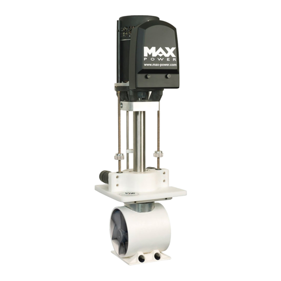
VERTICAL RETRACTABLE THRUSTER
VIP 250 ELECTRIC 24V
INSTALLATION
OPERATION
MAINTENANCE
Serial Number:.............................
Date of Installation:......................
THIS MANUAL MUST BE KEPT ON BOARD AT ALL TIMES
Via Philips 5, 20900, Monza, Italy
Tel.:+39 039 200 1973-936
Fax: +39 039 2004299
www .max-power.com
Advertisement
Table of Contents

Related Manuals for MAX power VIP 250 ELECTRIC 24V


Summary of Contents for MAX power VIP 250 ELECTRIC 24V
- Page 1 Last Update: November 2023 VERTICAL RETRACTABLE THRUSTER VIP 250 ELECTRIC 24V INSTALLATION OPERATION MAINTENANCE Serial Number:......Date of Installation:...... THIS MANUAL MUST BE KEPT ON BOARD AT ALL TIMES Via Philips 5, 20900, Monza, Italy Tel.:+39 039 200 1973-936 Fax: +39 039 2004299...
-
Page 2: Table Of Contents
VIP 250, 24V with Electronic Controller BEFORE STARTING THE INSTALLATION, IT IS RECOMMENDED TO CAREFULLY READ THE FOLLOWING GUIDE. TABLE OF CONTENTS Number Description Page POSITIONING DETERMINE THE LOCATION OF THE AUXILIARY EQUIPMENT MECHANICAL INSTALLATION MOUNTINING BASE INSTALLATION 3.1. 4 - 5 CONSTRUCTION OF HULL OPENING &... -
Page 3: Positioning
An electrical battery isolator, as supplied by Max Power, should be installed in the positive supply cable, as close as possible to the thruster battery bank, in order to benefit from all automatic safety features of the electronic control system. -
Page 4: Mechanical Installation
MOUNTING BASE INSTALLATION (Please refer to “Build Drawing” at back of this document ): MAX POWER can supply, either a reinforced G.R.P. mounting base or a 5086 aluminum alloy-mounting flange. These bases save considerable shipyard time while assuring solid and precise installation.... - Page 5 VIP 250, 24V with Electronic Controller The VIP pushes its thrust plate sideways against the inside of the mounting base when Mounting Base running. This means that one must totally Flange lower the unit and check the following: ( a ) Mounting Base That the VIP’s thrust plate is free to...
-
Page 6: Construction Of Hull Opening & Closing Plate
VIP 250, 24V with Electronic Controller 3.2 CONSTRUCTION OF HULL OPENING & CLOSING PLATE: The opening made for the thruster in the hull is closed by a plate, which can be made from the cutout hull section, or specially fabricated. a) The closing plate should fit into a 15 –... -
Page 7: Final Adjustment Of The Closing Plate
VIP 250, 24V with Electronic Controller 3.4 FINAL ADJUSTMENT OF THE CLOSING PLATE: Once the thruster is permanently bolted onto the mounting base, reinstall the closing plate to do the final adjustments. "Up" Position Detector Proximity ( b ) Switches ( d ) ( c ) -
Page 8: Electrical Installation
VIP 250, 24V with Electronic Controller When finished with the final adjustments, fix the alloy plate bracket by bolting through the GRP turbine in addition to the cable clamps. IMPORTANT: Please keep in mind that the power supply to up/down motors is not automatically interrupted if the proximity switches do not detect the position detectors. -
Page 9: Power Cable Selection
The Max Power fuse has been application selected for it’s time and current characteristics, consequently a much lower rated fuse than traditionally rated may be fitted. -
Page 10: Battery Requirements
An electrical battery isolator, as supplied by Max Power, should also be installed in the positive supply cable, as close as possible to the thruster battery bank, in order to... -
Page 11: Control Circuit
Please note that VIP thrusters equipped with an “electronic control box” can only be used with Max Power’s range of control panels as shown in this manual. The VIP electronic controller can be supplied in either 12V or 24V, depending on the thruster relay and up /down motor voltage. -
Page 12: Control Panel And Thruster Control Box Functions
VIP 250, 24V with Electronic Controller CONTROL PANEL AND THRUSTER CONTROL BOX FUNCTIONS: "On/Off" Push-button: Black with Green "On" LED. Control Panel: To switch "ON" or "OFF" push down the black push-button, while pushing Joystick joystick to the right for one second. To "Lower"... - Page 13 VIP 250, 24V with Electronic Controller 4.7.3 Thrusting "Left" or "Right": a) Use joystick to thrust either left or right. b) Please note that it is only possible to thrust left or right when thruster is detected to be fully down. c) The thruster controller provides a time delay between left and right thrust in order to avoid rapid direction changes, but no delay when thrusting to same side.
-
Page 14: Tests & Checks
VIP 250, 24V with Electronic Controller TESTS and CHECKS 5.1 BEFORE LAUNCHING: a) Raise and lower thruster. b) Check that the hull closing plate shuts firmly. c) Confirm that all bolts have been sufficiently tightened, especially the base bolts. d) Correct the adjustment of the position detectors, if needed. ... -
Page 15: Basic Maintenance
Do not use aggressive solvents as they might damage drive leg seals. f) If drive leg oil seals are found to be worn, replace drive leg with exchange unit. g) Always keep the propellers and tunnel clean. h) Please contact your closest Max Power distributor for local service points. -
Page 16: General
Every two years change column seal, part number 52 on parts list. For more detailed maintenance procedures, please contact your closest Max Power distributor (See “ Distributor Contact List ”) for further assistance. -
Page 17: Principal Dimensions
3RD ANGLE PROJECTION 370mm 370mm 1134mm Stroke 295mm Stroke 295mm Hull parts UNLESS TITLE REVISION PART NO. OTHERWISE VIP 250, 24V Principal Dimensions SPECIFIED CADD REF. MATERIAL SCALE Max Power DRAWN CHECK RELEASE HEAT TREAT & FINISH DATE DATE DATE 12/06/15... -
Page 18: Build Drawings
290mm 290mm 10mm Gussets 330mm 295mm Sikaflex Gasket Construction Point 290mm 10mm Other Hull Shape Other Hull Shape TITLE: Build Drawing PRODUCT REFERENCE: VIP 250, Electr.. DRAWN: REVISION: DATE: 12/06/15... -
Page 19: Wiring Diagram
VII' 250, 24V with Electronic Controller WIRING DIAGRAM " • •... -
Page 20: Electronic Control Box Connections
Orange ( Raise ) Panel Black On LED Up Purple LED Down Green Yellow Alarm Not Used Neg. MAX POWER To "Up" and "Down" Left Controller Down Position Proximity Neg. Type MP - VIP To Thruster Right Switches Relay Coils... -
Page 21: Parts Lists & Diagrams
VIP 250, 24V with Electronic Controller PARTS LISTS & DIAGRAMS : 9.1 PARTS LIST & DIAGRAM: A N° DESCRIPTION: Qty. Code 313735 Motor Relay Cover Electric Thruster Motor 24V 312871 Complete Thruster Relay 24V 315322 Motor/Relay Wiring Loom 635660 Coupling Motor Side 630487 Rubber Coupling 633743... -
Page 22: Parts Diagram: B
VIP 250, 24V with Electronic Controller TITLE: Parts List: A PRODUCT REFERENCE: VIP 250, Electric DRAWN: REVISION: DATE: PARTS DIAGRAM: B... - Page 23 REVISION PART NO. 3RD ANGLE PROJECTION UNLESS TITLE REVISION PART NO. Parts List: B OTHERWISE VIP 250, Electr SPECIFIED CADD MATERIAL REF. SCALE Max Power DRAWN CHECK RELEASE HEAT TREAT & FINISH POWER DATE DATE DATE...
- Page 24 Description Old Code 315321 Composite Leg Leg Bolts Propeller 35032 Propeller Grub Screw Propeller Pin Nyloc Nut 8mm Machine Washer Coter Pin Water Gland Retaining Ring Water Gland Sliding Shaft Plate Shaft Plate O - Ring Sliding Shaft Sliding Shaft Bolt Torque Transmission Plate Sliding Shaft O - Ring Shaft Key...
- Page 25 The warranty as outlined above is only applicable to Max Power manufactured thrusters and optional equipment as used in marin e pleasure industry. The supplier holds the exclusive right to test the produ ct and...
Need help?
Do you have a question about the VIP 250 ELECTRIC 24V and is the answer not in the manual?
Questions and answers