Table of Contents
Advertisement
Quick Links
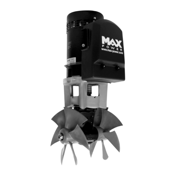
Manual CT165 & CT225
CT165 / CT225
With electronic thruster control
INSTALLATION OPERATION MAINTENANCE
Serial No.: ------------------------------------------------------
Installation date: -------------------------------------------------
THIS MANUAL MUST BE KEPT ONBOARD AT ALL TIMES
Via Philips 5, 20900 Monza (MI), Italy
Tel. +39 039 200 1973-936 - Fax +39 039 2004299
www.max-power.com
E-mail:contact@max-power.com
www.max-power.com
Last update: December 2013
Advertisement
Table of Contents


Need help?
Do you have a question about the CT165 and is the answer not in the manual?
Questions and answers