Table of Contents
Advertisement
Manual CT35-IP & CT45IP
Last update:December 2013
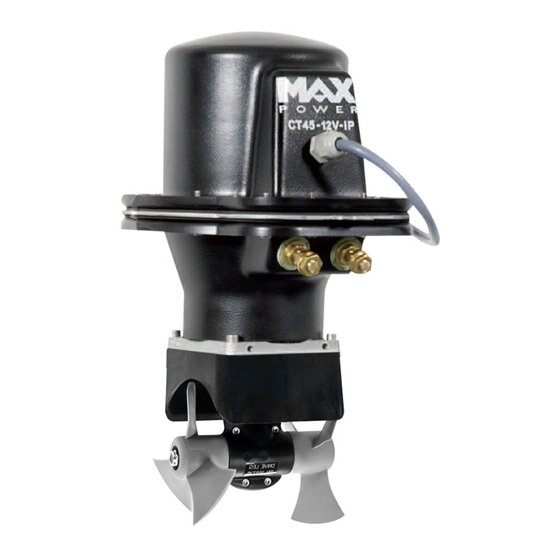
CT35-IP / CT45-IP
Ignition Protected Thruster
With electronic thruster control
CERTIFIED ISO 8846
INSTALLATION OPERATION MAINTENANCE
Serial No.: ------------------------------------------------------
Installation date: -------------------------------------------------
THIS MANUAL MUST BE KEPT ONBOARD AT ALL TIMES
Via Philips 5, 20900 Monza (MI), Italy
Tel. +39 039 200 1973-936 - Fax +39 039 2004299
www.max-power.com
E-mail:contact@max-power.com
www.max-power.com
Advertisement
Table of Contents

Related Manuals for MAX power CT35-IP


Summary of Contents for MAX power CT35-IP
- Page 1 Manual CT35-IP & CT45IP Last update:December 2013 CT35-IP / CT45-IP Ignition Protected Thruster With electronic thruster control CERTIFIED ISO 8846 INSTALLATION OPERATION MAINTENANCE Serial No.: ------------------------------------------------------ Installation date: ------------------------------------------------- THIS MANUAL MUST BE KEPT ONBOARD AT ALL TIMES Via Philips 5, 20900 Monza (MI), Italy Tel.
-
Page 2: Table Of Contents
Manual CT35-IP & CT45IP Last update:December 2013 Contents Section Title Page General installation guidelines Tunnel Composite motor support and drive leg Electric Motor Propellers Protection grills Electrical installation Main power fuse Batteries Electronic control box Control panel and thruster control box functions... -
Page 3: General Installation Guidelines
For the CT35-IP mono, the propeller must be centred in the tunnel. In the case of the CT45-IP duo, the drive leg must be centered in the tunnel In no case should the propellers of either models protrude out of the tunnel. -
Page 4: Tunnel
Manual CT35-IP & CT45IP Last update:December 2013 2. TUNNEL Once the final tunnel position has been determined and all dimensions have been checked, mark the centre-point of the tunnel on both sides of the hull and drill holes of 8 –10 mm ∅ on either side. -
Page 5: Composite Motor Support And Drive Leg
Manual CT35-IP & CT45IP Last update:December 2013 DO NOT LAMINATE THE AREA OF THE TUNNEL TO WHICH THE ELECTRICAL MOTOR SUPPORT WILL BE FIXED. 3. COMPOSITE MOTOR SUPPORT AND DRIVE LEG For the CT35-IP (Mono): The propeller must be at the center of the tunnel. The motor support and the drive leg will therefore not be centered in the tunnel. -
Page 6: Electric Motor
Manual CT35-IP & CT45IP Last update:December 2013 positioning and then tightening the two 6mm ∅ screws alternatively using a 5mm Allen key (maximum torque: 12 Nm). Check that the propellers rotate freely, without resistance or friction. It is imperative that the holes and the screws remain free of sealing compound, otherwise there is a risk of an incorrect assembly of the parts. -
Page 7: Main Power Fuse
These values are given as an indication, assuming that the batteries are charged at 100% and in charge, that is 13.8V. The performance data of the CT35-IP / CT45-IP is measured with an approx. consumption of 250 Amps and approx. 11V at the motor’s connections. -
Page 8: Electronic Control Box
Max Power advises the use of an electric battery isolator ref. OPTI3160/3. If an electric battery isolator is not used then simply seal-off the two grey wires coming out of the control box. -
Page 9: Control Panel Installation
Manual CT35-IP & CT45IP Last update:December 2013 12. CONTROL PANEL INSTALLATION Control panels should be protected from the natural elements while the thruster is not in use. Install the control panel(s) in easily accessible positions, without obstructing the main engine and/or steering controls. -
Page 10: Electrical Measurements
Manual CT35-IP & CT45IP Last update:December 2013 14. ELECTRICAL MEASUREMENTS In normal “usage” mode, i.e. thrusters running, boat in the water, with fully charged batteries under ongoing charge (alternator), electrical measurements should be made at the following points: At the batteries... -
Page 11: Safety
Opening or modifying the thruster may result in it no longer being Ignition Protected. In case of a problem please contact your local Max Power distributor Control panels should be protected from the natural elements while the thruster is not in use. -
Page 12: Electrical Installation Diagram
Manual CT35-IP & CT45IP Last update:December 2013 19. ELECTRICAL INSTALLATION DIAGRAM www.max-power.com... -
Page 13: Relay And Control Box Connections Diagram
Manual CT35-IP & CT45IP Last update:December 2013 20. RELAY AND CONTROL BOX CONNECTIONS www.max-power.com... -
Page 14: Spare Parts Diagram
Manual CT35-IP & CT45IP Last update:December 2013 21. SPARE PARTS DIAGRAM www.max-power.com... -
Page 15: Spare Parts List
22. SPARE PARTS LIST N° Description Quantités Référence Upper motor casing MPOP5835/SUP Backing flange MPOP5215 Relay 12V MP053028/2 Electric Motor CT35-IP / CT45-IP MP023000 Flange gasket MPOP5831 Centre flange MPOP5214 Lower motor casing MPOP5835/INF Motor fixing screws MP024030 MP025095 Motor drive pin and spring... -
Page 16: Troubleshooting Guide
Manual CT35-IP & CT45IP Last update:December 2013 23. TROUBLESHOOTING GUIDE Before contacting your nearest Max Power distributor, please check the below troubleshooting guide. Problem Check The control panel does not light • Check the 6 wire connector behind the joystick •... -
Page 17: Warranty Coverage
The warranty as outlined above is only applicable to Max Power manufactured thrusters and optional equipment as used in marine pleasure industry. The supplier holds the exclusive right to test the product and...
Need help?
Do you have a question about the CT35-IP and is the answer not in the manual?
Questions and answers