Table of Contents
Advertisement
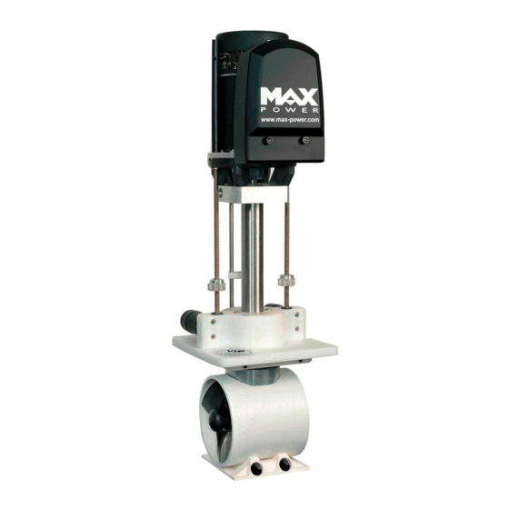
VERTICAL RETRACTABLE THRUSTER
VIP 150 ELECTRIC
12/24V
INSTALLATION
OPERATION
MAINTENANCE
Serial Number:.............................
Date of Installation:......................
THIS MANUAL MUST BE KEPT ON BOARD AT ALL TIMES
Via Philips 5, 20900, Monza, Italy
Tel.:+39 039 200 1973-936
Fax: +39 039 2004299
e-mail : mp@max-power.com
www.max-power.com
Advertisement
Table of Contents

Related Manuals for MAX power VIP 150 Electric


Summary of Contents for MAX power VIP 150 Electric
- Page 1 VERTICAL RETRACTABLE THRUSTER VIP 150 ELECTRIC 12/24V INSTALLATION OPERATION MAINTENANCE Serial Number:......Date of Installation:...... THIS MANUAL MUST BE KEPT ON BOARD AT ALL TIMES Via Philips 5, 20900, Monza, Italy Tel.:+39 039 200 1973-936 Fax: +39 039 2004299 e-mail : mp@max-power.com...
-
Page 2: Table Of Contents
VIP 150, 12/24V with Electronic Controller 25/12/05 BEFORE STARTING THE INSTALLATION, IT IS RECOMMENDED TO CAREFULLY READ THE FOLLOWING GUIDE. TABLE OF CONTENTS Number Description Page POSITIONING DETERMINE THE LOCATION OF THE AUXILIARY EQUIPMENT MECHANICAL INSTALLATION MOUNTINING BASE INSTALLATION 3.1. 4 - 5 CONSTRUCTION OF HULL OPENING &... -
Page 3: Positioning
An electrical battery isolator, as supplied by Max Power, should be installed in the positive supply cable, as close as possible to the thruster battery bank, in order to benefit from all automatic safety features of the electronic control system. -
Page 4: Mechanical Installation
MOUNTING BASE INSTALLATION (Please refer to “Build Drawing” at back of this document MAX POWER can supply, either a steel reinforced G.R.P. mounting base or a 5086 aluminium alloy-mounting flange. These bases save considerable shipyard time while assuring solid and precise installation. - Page 5 VIP 150, 12/24V with Electronic Controller 25/12/05 The VIP pushes its thrust plate sideways Mounting against the inside of the mounting base Base when running. This means that one must Flange ( a ) Mounting totally lower the unit and check the Base following: ( b )
-
Page 6: Construction Of Hull Opening & Closing Plate
VIP 150, 12/24V with Electronic Controller 25/12/05 3.2 CONSTRUCTION OF HULL OPENING & CLOSING PLATE: The opening made for the thruster in the hull is closed by a plate, which can be made from the cutout hull section, or specially fabricated. a) The closing plate should fit into a 15 –... -
Page 7: Final Adjustment Of The Closing Plate
VIP 150, 12/24V with Electronic Controller 25/12/05 3.4 FINAL ADJUSTMENT OF THE CLOSING PLATE: Once the thruster is permanently bolted onto the mounting base, reinstall the closing plate to do the final adjustments. "Up" Position Detector Proximity ( b ) Switches ( d ) ( c ) -
Page 8: Electrical Installation
VIP 150, 12/24V with Electronic Controller 25/12/05 When finished with the final adjustments, fix the alloy plate bracket by bolting through the GRP turbine in addition to the cable clamps. IMPORTANT: Please keep in mind that the power supply to up/down motors is not automatically interrupted if the proximity switches do not detect the position detectors. -
Page 9: Power Cable Selection
Fuse The Max Power fuse has been application selected for it’s time and current characteristics, consequently a much lower rated fuse than traditionally rated may be fitted. Max... -
Page 10: Battery Requirements
An electrical battery isolator, as supplied by Max Power, should also be installed in the positive supply cable, as close as possible to the thruster battery bank, in order to benefit... -
Page 11: Control Circuit
Please note that VIP thrusters equipped with an “electronic control box” can only be used with Max Power’s range of control panels as shown in this manual. The VIP electronic controller can be supplied in either 12V or 24V, depending on the thruster relay and up /down motor voltage. -
Page 12: Control Panel And Thruster Control Box Functions
VIP 150, 12/24V with Electronic Controller 25/12/05 CONTROL PANEL AND THRUSTER CONTROL BOX FUNCTIONS: "On/Off" Push-button: Black with Green "On" LED. Control Panel: To switch "ON" or "OFF" push down the black push-button, while pushing Joystick joystick to the right for one second. To "Lower"... - Page 13 VIP 150, 12/24V with Electronic Controller 25/12/05 4.7.3 Thrusting "Left" or "Right": a) Use joystick to thrust either left or right. b) Please note that it is only possible to thrust left or right when thruster is detected to be fully down.
-
Page 14: Tests & Checks
VIP 150, 12/24V with Electronic Controller 25/12/05 TESTS and CHECKS 5.1 BEFORE LAUNCHING: a) Raise and lower thruster. b) Check that the hull closing plate shuts firmly. c) Confirm that all bolts have been sufficiently tightened, especially the base bolts. d) Correct the adjustment of the position detectors, if needed. -
Page 15: Basic Maintenance
Do not use aggressive solvents as they might damage drive leg seals. f) If drive leg oil seals are found to be worn, replace drive leg with exchange unit. g) Always keep the propellers and tunnel clean. h) Please contact your closest Max Power distributor for local service points. -
Page 16: Bronze Drive Leg
Always keep the propellers and tunnel clean. g) Do not paint the anode. h) Please contact your closest Max Power distributor for local service points. 7.6 GENERAL: a) Regularly check that the power cable connections are tightened correctly and that they are free to move when VIP is going up/down, and that they are in good condition. -
Page 17: Drawings & Diagrams
VIP 150, 12/24V with Electronic Controller 25/12/05 DRAWINGS & DIAGRAMS: 8.1 PRINCIPAL DIMENSIONS:... -
Page 18: Build Drawings
VIP 150, 12/24V with Electronic Controller 25/12/05 8.2 BUILD DRAWING: 13,00mm... -
Page 19: Wiring Diagram
VIP 150, 12/24V with Electronic Controller 25/12/05 8.3 WIRING DIAGRAM:... -
Page 20: Electronic Control Box Connections
VIP 150, 12/24V with Electronic Controller 25/12/05 ELECTRONIC CONTROL BOX CONNECTIONS: Motor Limit Switches Heat Control Panel... -
Page 21: Wiring Of Additional Control Panels For Vip Thrusters
VIP 150, 12/24V with Electronic Controller 25/12/05 8.5 WIRING OF ADDITIONAL CONTROL PANELS FOR VIP THRUSTERS: PARTS LISTS & DIAGRAMS : 9.1 PARTS LIST & DIAGRAM: A NEW CODE: N° DESCRIPTION: Qty. MP082021 313735 Motor Relay Cover Electric Thruster Motor 12V MP083010 312869 Electric Thruster Motor 24V... -
Page 22: Parts Diagram: B
VIP 150, 12/24V with Electronic Controller 25/12/05 TITLE: Parts List: A PRODUCT REFERENCE: VIP 150, Electric DRAWN: REVISION: DATE: PARTS DIAGRAM: B... -
Page 23: Parts List: B
VIP 150, 12/24V with Electronic Controller 25/12/05 9.3 PARTS LIST: B... - Page 24 Description New Code: Old Code Composite Leg MP088100 16. 35035 Leg Bolts MPOP 5340 22. 634204 Propeller MPOP 5230 25. 35031 Propeller Grub Screw OPTI 4040 26. 634518 Propeller Pin MPOP 5220 27. 312054 Nyloc Nut 8mm VPO8 4190 48. 635604 Machine Washer VPO8 5390 49.
- Page 25 The purpose of this document is to set out the terms of warranty cover offered in relation to products purchased by the End User from Max Power or its approved network of resellers. This document will adhere to the following format:- 10.1 DEFINITIONS...
-
Page 26: Warranty Coverage
PRIOR TO CONTACTING THE DEALER/INSTALLER Contact your dealer/installer to report the problem. a) If you do not know who this is, contact the nearest Max Power distributor. b) If you are in foreign waters please contact the nearest Max Power distributor. - Page 27 VIP 150, 12/24V with Electronic Controller 25/12/05 CYPRUS CYPRUS OCEAN MARINE EQUIPMENT LTD TUTI MARE TRADING Limassol Limassol Tel: + 357 53 69 731 Tel: + 357 25 431 313 Fax: + 357 53 52 976 Fax: + 357 25 431 300 Email: oceanm@spidernet.com.cy Email: tutimare@cytanet.com.cy...
- Page 28 VIP 150, 12/24V with Electronic Controller 25/12/05 NORWAY SWEDEN PROGRESS INGENIORFIRMA AS PLASTIMO NORDIC Kjeisaas Henan Tel: + 47 22 02 79 00 Tel: + 46 304 360 60 Fax: + 47 22 02 79 01 Fax: + 46 304 307 43 Email: thomas@progressing.no Email: mikael.andersson@navimo.se...
-
Page 29: Warranty Form
VERY IMPORTANT COPY Please complete this form and fax a to Max Power with a copy of the installation invoice or the invoice of the yacht/boat in order for the warranty to come into effect. To Be Completed by Owner: Name of Owner:…………………………….
Need help?
Do you have a question about the VIP 150 Electric and is the answer not in the manual?
Questions and answers