Advertisement
Quick Links
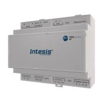
Installation Guide for the IN770PAN⁎⁎⁎O000 Gateway for Panasonic AC Systems
The order code may vary depending on the product seller and the buyer's location.
⁎⁎⁎ stands for the gateway capacity and varies depending on the specific gateway purchased.
Version 2.0.3
Owner's record
Find the serial number on the silver label on the right side of the gateway. For sales or technical
assistance, we recommend writing it in the space below:
SN:
Safety Instructions
Follow these safety and installation instructions carefully. Improper work may
lead to serious harm to your health and may seriously damage this Intesis
gateway and/or any other installation equipment.
Only accredited technical personnel, following all these safety instructions and in accordance with
the country's legislation for the installation of electric equipment, are authorized to install this
Intesis gateway.
Install this Intesis gateway indoors, in a restricted access location, and sheltered from direct solar
radiation, water, high relative humidity, or dust.
Mount this Intesis gateway, preferably, on a DIN rail inside a grounded metallic cabinet following the
instructions below.
In the case of wall mounting, firmly fix this Intesis gateway on a non-vibrating surface following the
instructions below.
Disconnect any wires from its power source before manipulating and connecting them to this Intesis
gateway.
Use a SELV-rated NEC Class 2 or Limited Power Source (LPS) power supply.
Use a circuit breaker before the power supply. Rating: 250 V, 6 A.
Respect the expected polarity of power and communication cables when wiring this gateway.
Supply the correct voltage to power this Intesis gateway. The admitted range voltage is detailed in
the technical specifications table.
Connect this Intesis gateway only to networks without routing to the outside
plant. All communication ports are considered indoor only.
This Intesis gateway is designed for installation in an enclosure. To avoid electrostatic discharges to
the unit in environments with static levels above 4 kV, precautions should be taken when the device
is mounted outside an enclosure. When working in an enclosure (ex. making adjustments, setting
switches etc.) typical anti-static precautions should be observed before touching the unit.
Safety instructions in other languages can be found at:
Configuration
Connect the gateway to a computer using the USB Mini-B type to USB Type A cable (included).
Configure the gateway using Intesis MAPS. Download the latest version of the configuration tool
at www.intesis.com/products/intesis-maps.
For further information on the configuration, refer to the
Mounting
Mount the gateway on a wall or over a DIN rail. We recommend the DIN rail
mounting option, preferably inside a grounded metallic industrial cabinet.
Wall mounting
1.
Press the top-side mobile clips in the rear panel until you hear a click.
2.
Use the clip holes to fix the gateway on the wall using screws.
Use M3 screws, 25 mm (1") length.
3.
Make sure the gateway is firmly fixed.
https://intesis.com/docs/manuals/v6-safety
Configuration
Guide.
© HMS Industrial Networks SLU | www.hms-networks.com
Installation Guide | Publication date: 2024-04-15
DIN rail mounting
Keep the clips in their original position.
1.
Fit the gateway's top-side clips in the upper edge of the DIN rail.
2.
Press the low side of the gateway gently to lock it in the DIN rail.
3.
Make sure the gateway is firmly fixed.
For some DIN rails, to complete step 2, you may need a small screwdriver
or similar to pull the bottom clip down.
Connections
Power supply: Use a SELV-rated NEC class 2 or Limited Power Source (LPS) power supply. Connect
the gateway's ground terminal (
) to the installation grounding.
Power rating:
• For DC: 12 .. 36 VDC ±10%, Max: 250 mA
• For AC: 24 VAC ±10 %, 50-60 Hz, Max: 127 mA
Recommended voltage: 24 VDC, Max: 127 mA
Advertisement

Related Manuals for HMS Networks Intesis IN770PAN O000 Series


Summary of Contents for HMS Networks Intesis IN770PAN O000 Series
- Page 1 Installation Guide | Publication date: 2024-04-15 Installation Guide for the IN770PAN⁎⁎⁎O000 Gateway for Panasonic AC Systems The order code may vary depending on the product seller and the buyer's location. DIN rail mounting ⁎⁎⁎ stands for the gateway capacity and varies depending on the specific gateway purchased. Keep the clips in their original position.
- Page 2 Installation Guide | Publication date: 2024-04-15 Technical Specifications Communication ports: PORT USAGE WIRING Plastic, type PC (UL 94 V-0). Color: Light Grey. RAL 7035 BACnet MS/TP and SG: Signal Housing Net dimensions (dxwxh): Millimeters: 90 x 106 x 58 mm / Inches: 3.5 x 4.2 x EIA-485 Modbus RTU ground...
Need help?
Do you have a question about the Intesis IN770PAN O000 Series and is the answer not in the manual?
Questions and answers