HMS Networks Intesis 700 Series User Manual
Mitsubishi heavy industries vrf systems to modbus, knx, bacnet, and home automation
Hide thumbs
Also See for Intesis 700 Series:
- Manual (69 pages) ,
- User manual (50 pages) ,
- User manual (40 pages)

Subscribe to Our Youtube Channel
Related Manuals for HMS Networks Intesis 700 Series


Summary of Contents for HMS Networks Intesis 700 Series
- Page 1 ENGLISH 700series Air Gateway - IN776MHI⁎⁎⁎O000 MITSUBISHI HEAVY INDUSTRIES VRF SYSTEMS to Modbus, KNX, BACnet, and Home Automation USER MANUAL Version 1.2.12 Publication date 2024-09-04...
- Page 2 The information in this document shall therefore not be construed as a commitment on the part of HMS Networks and is subject to change without notice. HMS Networks makes no commitment to update or keep current the information in this document.
-
Page 3: Table Of Contents
700series Air Gateway - IN776MHI⁎⁎⁎O000 Table of Contents 1. Description, Compatible AC systems, and Order Codes ..............1 2. Licensing ..........................2 3. General Information ........................ 3 3.1. Intended Use of the User Manual ..................3 3.2. General Safety Information ....................3 3.3. -
Page 4: Description, Compatible Ac Systems, And Order Codes
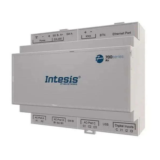
Description, Compatible AC systems, and Order Codes 700series Air Gateway - IN776MHI⁎⁎⁎O000 1. Description, Compatible AC systems, and Order Codes IN776MHI⁎⁎⁎O000 Gateway. Modbus®, KNX®, BACnet®, and Home Automation gateway for Mitsubishi Heavy Industries® HVAC systems. This gateway is compatible with VRF units commercialized by Mitsubishi Heavy Industries. Use the compatibility tool to get a complete list of compatible units: https://compatibility.intesis.com/ You can set up this Intesis gateway for Modbus TCP, Modbus RTU, KNX TP, BACnet/IP, BACnet MS/TP, or Home... -
Page 5: Licensing
700series Air Gateway - IN776MHI⁎⁎⁎O000 Licensing 2. Licensing Distribution license(s) for the IN776MHI⁎⁎⁎O000 gateway: Maximum AC units Order Code License Indoor units Outdoor units IN776MHIXXSO000 IN776MHI00SO000 Small IN776MHI00MO000 Medium IN776MHI00LO000 Large See note See note NOTE For IN776MHI00LO000, the maximum number of indoor units you can integrate depends on the number of integrated outdoor units. -
Page 6: General Information
General Information 700series Air Gateway - IN776MHI⁎⁎⁎O000 3. General Information 3.1. Intended Use of the User Manual This manual contains the main features of this Intesis gateway and the instructions for its appropriate installation, configuration, and operation. Any person who installs, configures, or operates this gateway or any associated equipment should be aware of this manual's contents. -
Page 7: Admonition Messages And Symbols
700series Air Gateway - IN776MHI⁎⁎⁎O000 Admonition Messages and Symbols This Intesis gateway is designed for installation in an enclosure. When the device is mounted outside an enclosure, precautions should be taken to avoid electrostatic discharges to the unit in environments with static levels above 4 kV. -
Page 8: Overview
Overview 700series Air Gateway - IN776MHI⁎⁎⁎O000 4. Overview This IN776MHI⁎⁎⁎O000 gateway supports four combinations. Gateway's client interface ↔ Gateway's server interface Modbus TCP and RTU KNX TP Mitsubishi Heavy Industries VRF systems BACnet/IP or MS/TP Home Automation IMPORTANT This document assumes that the user is familiar with these technologies. Figure 1. -
Page 9: Inside The Package
700series Air Gateway - IN776MHI⁎⁎⁎O000 Inside the Package Figure 3. Integration of Mitsubishi Heavy Industries units into BACnet systems Figure 4. Integration of Mitsubishi Heavy Industries units into Home Automation systems 4.1. Inside the Package ITEMS INCLUDED • Intesis IN776MHI⁎⁎⁎O000 Gateway •... -
Page 10: Gateway General Functionality
Gateway General Functionality 700series Air Gateway - IN776MHI⁎⁎⁎O000 • Scan function: Find the AC units connected to the air conditioning bus. • Specific signals to monitor outdoor units. • 2 x DIP switches for the EIA-485 connector termination and polarization configuration. •... -
Page 11: Quick Start Guide
700series Air Gateway - IN776MHI⁎⁎⁎O000 Quick Start Guide 5. Quick Start Guide IMPORTANT While the following procedure outlines the fundamental steps for installing, wiring, and configuring the gateway, it is crucial to thoroughly review all documentation to prevent errors. Install Intesis MAPS on your laptop. -
Page 12: Hardware
Hardware 700series Air Gateway - IN776MHI⁎⁎⁎O000 6. Hardware 6.1. Mounting IMPORTANT Before mounting, please ensure that the chosen installation place preserves the gateway from direct solar radiation, water, high relative humidity, or dust. NOTE Mount the gateway on a wall or over a DIN rail. We recommend the DIN rail mounting option, preferably inside a grounded metallic industrial cabinet. -
Page 13: Din Rail Mounting
700series Air Gateway - IN776MHI⁎⁎⁎O000 Mounting DIN RAIL MOUNTING Keep the clips in their original position. Fit the gateway’s top-side clips in the upper edge of the DIN rail. Press the low side of the gateway gently to lock it in the DIN rail. Make sure the gateway is firmly fixed. -
Page 14: Connection
Connection 700series Air Gateway - IN776MHI⁎⁎⁎O000 6.2. Connection CAUTION Disconnect all systems from power before manipulating and connecting them to the gateway. IMPORTANT Keep communication cables away from power and ground wires. 6.2.1. Gateway Connectors Figure 5. Wiring diagram USER MANUAL Version 1.2.12 Page 11 of 37... -
Page 15: Wiring The Connectors
700series Air Gateway - IN776MHI⁎⁎⁎O000 Connection WIRING THE CONNECTORS IMPORTANT For all connectors, use solid or stranded wires (twisted or with ferrule). Cross-section/gauge per terminal: • One core: 0.2 .. 2.5 mm / 24 .. 11 AWG • Two cores: 0.2 .. 1.5 mm / 24 .. -
Page 16: Connection To The Power Supply
Connection 700series Air Gateway - IN776MHI⁎⁎⁎O000 6.2.2. Connection to the Power Supply The power supply connector is a green pluggable terminal block (three poles) labeled as Power. Apply the voltage within the admitted range and of enough power: • For DC: 12 .. 36 VDC (±10%), Max: 250 mA •... -
Page 17: Wiring Considerations
700series Air Gateway - IN776MHI⁎⁎⁎O000 Connection WIRING CONSIDERATIONS • Maximum wiring length: 1000 meters (0.75 miles). • Loop wiring is not allowed. NOTE For the Mitsubishi Heavy Industries domestic series with an SC-BIKN-E connector, you need an SC-ADNA-E adapter (not included). NOTE See the Wiring diagram (page... -
Page 18: Connection To Knx
Connection 700series Air Gateway - IN776MHI⁎⁎⁎O000 IMPORTANT Observe the standard restrictions of the EIA-485 bus: • Maximum distance of 1200 meters (0.75 miles). • Maximum of 32 devices connected to the bus. • A 120 ohms (Ω) termination resistor is needed at each end of the bus. The gateway has an internal bus biasing circuit incorporating the termination resistor. - Page 19 700series Air Gateway - IN776MHI⁎⁎⁎O000 Connection NOTE When commissioning the gateway for the first time, DHCP will be enabled for 30 seconds. During that time, if there is a DHCP server, an IP address will be automatically assigned to the gateway. After that time, the default IP address 192.168.100.246 will be automatically set.
-
Page 20: Connection To Home Automation
Connection 700series Air Gateway - IN776MHI⁎⁎⁎O000 6.2.7. Connection to Home Automation Connect the Home Automation Ethernet cable to the gateway's Ethernet Port. The correct cable to use depends on where the gateway is connected: • Connecting directly to a Home Automation device: use a crossover Ethernet UTP/FTP CAT5 or higher cable. •... -
Page 21: Gateway Layout
700series Air Gateway - IN776MHI⁎⁎⁎O000 Gateway Layout 6.3. Gateway Layout Figure 6. Disposition of hardware elements in the gateway Plastic covers numbered in the image as ①, ②, ③, and ④ can be easily disassembled. NOTE LEDs and DIP switches are hidden behind the removable plastic covers and can only be accessed by disassembling the covers. -
Page 22: Led Indicators
LED Indicators 700series Air Gateway - IN776MHI⁎⁎⁎O000 6.4. LED Indicators Table 1. LEDs location and behavior Cover Color Description Top side LED 1 (PWR) Green Power on (not programmable) LED 2 (ERR) Blinking: Hardware error Under frontal cover ① LED 3 Green 485 Tx (RS485 for BACnet or Modbus) LED 4... -
Page 23: Dip Switches
700series Air Gateway - IN776MHI⁎⁎⁎O000 DIP Switches 6.5. DIP Switches The gateway has two DIP switches (see the figure Disposition of hardware elements in the gateway (page 18)): • DIP switch A (SW A) • DIP switch B (SW B) Each DIP switch is dedicated to a 485 port, and its function is to activate or deactivate the termination resistor (position 1) and the polarization (positions 2 and 3) of each port: Position... -
Page 24: Technical Specifications
Technical Specifications 700series Air Gateway - IN776MHI⁎⁎⁎O000 6.7. Technical Specifications Plastic, type PC (UL 94 V-0). Color: Light Grey. RAL 7035 Housing Net dimensions (HxWxD): Millimeters: 90 x 106 x 58 mm / Inches: 3.5 x 4.2 x 2.3" Wall: Use M3 25 mm (1") length screws. Secure mounting: below 2 meters (6 feet) Mounting DIN rail (recommended mounting) EN60715 TH35 Wire cross-section/gauge per terminal:... -
Page 25: Dimensions
700series Air Gateway - IN776MHI⁎⁎⁎O000 Dimensions 6.8. Dimensions NET DIMENSIONS (HxWxD) Millimeters: 90 x 106 x 58 mm Inches: 3.5 x 4.2 x 2.3" IMPORTANT Leave enough clear space to wire the gateway easily and for the subsequent manipulation of elements. -
Page 26: Available Protocol Combinations
Available Protocol Combinations 700series Air Gateway - IN776MHI⁎⁎⁎O000 7. Available Protocol Combinations 7.1. Integration into Modbus Systems 7.1.1. Modbus Registers NOTICE This part is common for Modbus RTU and TCP. Functions to read Modbus registers: • 03 Read Holding Registers. •... - Page 27 700series Air Gateway - IN776MHI⁎⁎⁎O000 Integration into Modbus Systems 1: Lock Remote Lock (all the units) 3000 R, W 0-Unlock Table 3. Outdoor unit registers Register name Possible values Modbus address (OU address[0..127] × 20) + OU Compressor 1 Frequency 0 ..
- Page 28 Integration into Modbus Systems 700series Air Gateway - IN776MHI⁎⁎⁎O000 0: Unlock Remote Lock (IU address[0..127] × 20) + 6 R, W 1-Lock 0: Swing 1: Position 1 Louver / Vane Position 2: Position 2 (IU address[0..127] × 20) + 7 R, W 3: Position 3 4: Position 4...
-
Page 29: Integration Into Knx Systems
700series Air Gateway - IN776MHI⁎⁎⁎O000 Integration into KNX Systems 7.2. Integration into KNX Systems 7.2.1. KNX The following tables list all available KNX signals for this gateway. NOTE Physical Address: The gateway supports (P/S) and (P/I/S) format levels. NOTICE Communication object flags: •... - Page 30 Integration into KNX Systems 700series Air Gateway - IN776MHI⁎⁎⁎O000 Table 6. Outdoor units Description Function Flags Status_OU Compressor 1 Frequency 14.033-DPT_Value_Frequency (4byte) R, T Status_OU Compressor 2 Frequency 14.033-DPT_Value_Frequency (4byte) R, T Status_OU Heat Exchange low 1 temperature °C / °F 9.001/9.027-DPT_Value_Temp (2byte) R, T Status_OU Heat Exchange low 2 temperature...
- Page 31 700series Air Gateway - IN776MHI⁎⁎⁎O000 Integration into KNX Systems Description Function Flags 0: Auto 1: Heat Control_Operation mode 2: Dry 5.x (1byte) Ri, W, U 3: Fan 4: Cool 0: Auto 1: Heat Status_Operation mode 2: Dry 5.x (1byte) R, T 3: Fan 4: Cool 0: Cool...
- Page 32 Integration into KNX Systems 700series Air Gateway - IN776MHI⁎⁎⁎O000 Description Function Flags Thresholds: Status_Fan speed scaling 5.001-DPT_Scaling (1byte) R, T 100% Control_Fan speed low 1: Set fan speed low 1.001-DPT_Switch (1bit) Ri, W, U 1: Speed low active Status_Fan speed low 1.001-DPT_Switch (1bit) R, T 0: Speed low not active...
- Page 33 700series Air Gateway - IN776MHI⁎⁎⁎O000 Integration into KNX Systems Description Function Flags Celsius: 0 .. 30 °C Status_AC ambient temperature 9.001/9.027-DPT_Value_Temp (2byte) R, T Fahrenheit: 32 .. 86°F Control_KNX ambient temperature °C / °F 9.001/9.027-DPT_Value_Temp (2byte) Ri, W, U 0: Normal Status_FilterSign 1.005-DPT_Alarm (1bit) R, T...
-
Page 34: Integration Into Bacnet Systems
Integration into BACnet Systems 700series Air Gateway - IN776MHI⁎⁎⁎O000 7.3. Integration into BACnet Systems NOTICE You can consult the Protocol Implementation Conformance Statement (PICS) document here. 7.3.1. BACnet Objects NOTICE This part is common for BACnet MS/TP and BACnet/IP. Input object types: •... - Page 35 700series Air Gateway - IN776MHI⁎⁎⁎O000 Integration into BACnet Systems Object name Possible values Type Object instance OUXX_Heat Exchange low 4 temperature °C / °F 0-Analog Input (OU[1..12] × 20) + 10000 + 5 OUXX_Heat exchange high 1 temperature °C / °F 0-Analog Input (OU[1..12] ×...
- Page 36 Integration into BACnet Systems 700series Air Gateway - IN776MHI⁎⁎⁎O000 1: Swing 2: Pos1 IUXX_Louver / Vane Position_S 3: Pos2 13-Multistate Input (IU[1..128] × 25) + 2 4: Pos3 5: Pos4 1: Swing 2: Pos1 IUXX_Louver / Vane Position_C 3: Pos2 14-Multistate Output (IU[1..128] ×...
-
Page 37: Integration Into Home Automation Systems
700series Air Gateway - IN776MHI⁎⁎⁎O000 Integration into Home Automation Systems 7.4. Integration into Home Automation Systems 7.4.1. Home Automation Signals The following tables list all available Home Automation signals for this gateway. NOTE • SET: Command used to control the indoor unit. It is sent by the client. •... -
Page 38: Late Configuration: Change The Gateway's Protocol
Late Configuration: Change the Gateway's Protocol 700series Air Gateway - IN776MHI⁎⁎⁎O000 8. Late Configuration: Change the Gateway's Protocol Reconfiguring the gateway with a different protocol is very easy: Connect the gateway to the PC and open the configuration tool Intesis MAPS. Select the new template you need. -
Page 39: Error Codes
700series Air Gateway - IN776MHI⁎⁎⁎O000 Error Codes 9. Error Codes NOTE These error codes are the same for all applications. Code in the wired Error code Description No active error Remote controller communication error Duplicated indoor unit address Outdoor unit signal line error Communication error during operation Indoor heat exchanger temperature thermistor anomaly Indoor return air temperature thermistor anomaly... - Page 40 Error Codes 700series Air Gateway - IN776MHI⁎⁎⁎O000 Code in the wired Error code Description Suction pipe temperature thermistor anomaly High/Low pressure sensor anomaly Underneath temperature thermistor anomaly Power transistor temperature thermistor anomaly Insufficient in refrigerant amount or detection of service valve closure Anomalous compressor by loss of synchronism Compressor startup failure...
Need help?
Do you have a question about the Intesis 700 Series and is the answer not in the manual?
Questions and answers