Advertisement
Quick Links
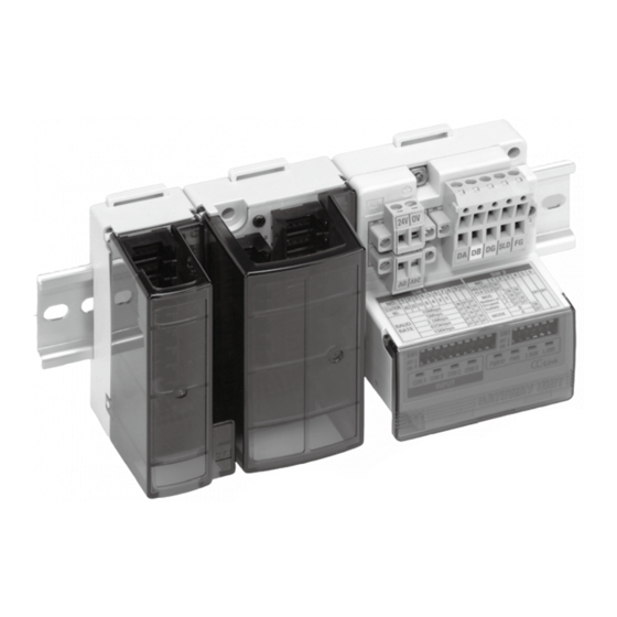
GW System, 4 Branches
EX510
Series
Compatible communication network
Compatible communication network
Pressure switch
Flow switch
Input device
2124
∗ Input units with
covers
16-point input unit
(interlinks 16 connectors)
∗ The product is shown
without a cover.
Two 2-wire auto switches can be
connected to a single connector.
n i t
G W u
16-point input unit
(interlinks 8 connectors)
∗ The product is shown
without a cover.
Auto switch
®
RoHS
Advertisement

Related Manuals for SMC Networks EX510 Series


Summary of Contents for SMC Networks EX510 Series
- Page 1 GW System, 4 Branches EX510 Series ® n i t G W u RoHS Compatible communication network Compatible communication network ∗ Input units with covers 16-point input unit (interlinks 16 connectors) ∗ The product is shown without a cover. 16-point input unit (interlinks 8 connectors) ∗...
- Page 2 S I u n d i n g I n c l u a l v e SY3000/5000 S0700 f o l d v m a n i (Plug-in) (Plug-in) VQZ1000/2000/3000 SY3000/5000 SYJ3000/5000/7000 (Plug-in) SJ2000/3000 SZ3000 S0700 SQ1000/2000 VQ1000/2000 EX12 EX140 EX180 EX260...
- Page 3 Features of Series EX510 Conventional Adoption of Series EX510 Programmable logic Programmable logic Power supply Power supply controller controller Including SI unit Including SI unit Including SI unit Input unit Serial transmission system manifold valve manifold valve manifold valve EX510 Including SI unit Including SI unit Including SI unit...
- Page 4 Compact SI unit Feature • The SI unit which connects output devices such as a solenoid valve has a compact design, compared with a existing model. (Compactness: volume ratio more than 60%) EX120 EX510 Existing model (Series Series Can flexibly change to Field Bus. Feature •...
- Page 5 Cable length of up to 20 meters is available. Feature Various units can be connected within a radius of 20 meters around the GW unit. i f o l d M a n i f o l d M a n v a l v i f o l d M a n...
- Page 6 Protection Feature Each unit is protected against a short-circuit from a power supply load. Input/Output unit fuses are replaceable. The short circuit protection is integrated for the SI unit. Replaceable fuse EX12 EX140 EX180 EX260 EX250 EX600 EX500 EX510 EX510 EX...
- Page 7 Number of inputs 64 inputs (16 inputs x 4 branches) ∗ Possible to change depending on the switch setting Connection input device The EX510 series input unit (connection from communication port A to D) Supply voltage 24 VDC Supply current Max.
- Page 8 EX510 Series GW System, 4 Branches Parts Description GW Unit Description Applications Communication socket For connecting with a network, using the communication connector ( !0 ) , which is part of the accessories. (BUS) Power supply socket Supplies power for output devices, which have a power supply (PWR(V)) connector ( !1 ) , such as a solenoid valve.
- Page 9 EX510 Series EX510-GMJ1 (CC-Link compliant) Display Setting Display Contents Indicator light condition HOLD/CLR setting The output power supply voltage is supplied as specified. Light is turned on. PWR(V) Setting of occupied The output power supply voltage is not supplied as specified. Light is turned off.
- Page 10 EX510 Series GW System, 4 Branches EX510-GDN1 (DeviceNet™ compliant) Display Setting HW/SW setting Display Contents Indicator light condition HOLD/CLR setting Number of The output power supply voltage is supplied as specified. Light is turned on. PWR(V) input settings Communication The output power supply voltage is not supplied as specified. Light is turned off.
- Page 11 EX510 Series EX510-GPR1 (PROFIBUS DP compliant) Display Setting HOLD/CLR Display Contents Indicator light condition Number of HW/SW The output power supply voltage is supplied as specified. Light is turned on. input settings PWR(V) The output power supply voltage is not supplied as specified. Light is turned off.
- Page 12 EX510 Series GW System, 4 Branches How to Order Input Unit EX510-DX N 1 EX510-DX Unit type Compatible sensor 1 connector, 2-input type NPN output Replaceable fuse 1 connector, 1 input type (EX9-FU10) PNP output 2-wire type Note) B (2-wire type) is available with 1 connector, 2-input type only. Specifications EX510-DXN...
- Page 13 EX510 Series Parts Description EX510-DX1 EX510-DX2 CN10 CN12 CN11 CN14 CN13 CN15 Shown with cover removed. Shown with cover removed. Accessories Branch connector (2 pcs.) Bracket EX510-LC1 ∗ Attached to Marker label EX510-DX1 only Input Unit Description Applications For press-fitting the branch connector ( o ) to the branch cable (EX510-FC) for Branch connector on the connecting with the GW unit.
- Page 14 EX510 Series GW System, 4 Branches Internal Circuits and Wiring Examples ... Input unit for 2-wire type (1 connector, 2-input type) EX510-DXB1 • Branch connector on the input unit side CN0 to CN7 Fuse (1A) For input +24 V For sensor +24 V IN11 IN11 IN13...
- Page 15 EX510 Series Internal Circuits and Wiring Examples ... Input unit for NPN (1 connector, 1 input type) EX510-DXN2 • Branch connector on the input unit side CN0, 2, 4, ... , 14 Fuse (1A) For input +24 V For sensor +24 V RD (+) IN11 IN13...
- Page 16 EX510 Series GW System, 4 Branches How to Order Output Unit EX510-DY P 3 Output specifications Connector type Sink/NPN output Terminal box type (Internal power supply) Source/PNP output Terminal box type (External power supply) Specifications EX510-DYN3 EX510-DYP3 EX510-DYN4 EX510-DYP4 Model Output type Sink/NPN (Positive common) Source/PNP (Negative common)
- Page 17 EX510 Series Parts Description Output Unit Description Applications For press-fitting the branch connector (!1 ) to Branch connector on the output unit the branch cable (EX510-FC) for connecting with GW unit. side Output terminal Connect the output load, etc. LED for power Light ON: Power supply ON (Normal) state Light OFF: Power supply OFF state supply...
- Page 18 EX510 Series GW System, 4 Branches Internal Circuits and Wiring Examples ... Output unit for NPN (External power supply type) EX510-DYN4 • Terminal Block Connector (CN1) Common for driving a load (–) Fuse (5A) Functions Common for driving a load (–) Description 1 2 3 For output +24 V...
- Page 19 EX510 Series Internal Circuits and Wiring Examples ... Output unit for PNP (External power supply type) EX510-DYP4 • Terminal Block Connector (CN1) +24V Fuse (5A) Functions For output +24 V Common for driving a load (+) Description TD (+) Common for driving a load (+) 1 2 3 TD (–) Common for driving a load (–)
- Page 20 EX510 Series GW System, 4 Branches How to Order SI Unit EX510-S Output specifications Mounting specifications Screw mounting Sink/NPN (Positive common) Mounting on DIN rail vertically Source/PNP (Negative common) Mounting on DIN rail horizontally Applicable valve manifold Mounting on DIN rail horizontally (Dedecated for the SJ manifold) Note) Plug-lead manifold...
- Page 21 EX510 Series Parts Description You can place an order for the manifold (valve series mentioned below) with the SI unit. For further information, please refer to the individual valve/manifold catalog. Also, you can change the system of your device by retrofitting the SI unit with the manifold already purchased. EX510-S01 EX510-S01A EX510-S01B...
- Page 22 EX510 Series GW System, 4 Branches Internal Circuits and Wiring Examples EX510-S001/NPN output (Connector for connecting a load) For load +24 V For output +24 V Load OUT0 – TD (+) OUT1 – output TD (–) For load +24 V Load For output 0 V Branch connector on...
- Page 23 EX510 Serial Wiring Compatible 5 Port Solenoid Valves Plug-lead Type Manifold Port size for A, B ports Applicable Sonic conductance: C Piping with One-touch fittings cylinder Thread piping Series /(sbar)] size Metric size Inch size (representative value) (reference) ø ø ø...
- Page 24 EX510 Series GW System, 4 Branches Plug-in Type Manifold Port size for A, B ports Applicable Sonic conductance: C Piping with One-touch fittings cylinder Thread piping Series /(sbar)] size Metric size (representative value) (reference) ø ø ø SJ2000 ø25 0.36 ...
- Page 25 EX510 Series System Composition/Options GW unit Input device Pressure switch Auto switch Flow switch q Branch cable A 4 core flat cable is required for connecting between units. How to Order EX510-FC 10 Cable length (L) Brown: +24 V Black: Communications + White: Communications –...
- Page 26 EX510 Series GW System, 4 Branches e Cable assembly for outputting EX510-VSS EX510-VSQ Cable assembly for connecting the unused outputs in the SI unit. How to Order EX510-V EX510-VWS EX510-VWQ Output Valve connector 1 point None 2 points For Series SY, SYJ For Series VQ, VQZ Note) Cable length (L)
- Page 27 EX510 Series Ordering Examples Shown is an example for ordering the EX510 series. DeviceNet™ communication line ∗ Cover not attached Branch connector (EX510-LC1) ∗ Cover not attached ∗ Cover not attached .......... q Gateway unit EX510-GDN1 1 unit (DeviceNet™ compliant) ......
- Page 28 EX510 Series Specific Product Precautions 1 Be sure to read before handling. Design and Selection Mounting Warning Caution 1. Use within the allowable voltage range. 1. Do not drop, bump, or apply excessive im- pact. Using beyond the allowable voltage range is likely to cause the units and connecting devices to be damaged or to malfunction.
- Page 29 EX510 Series Specific Product Precautions 2 Be sure to read before handling. Wiring Operating Environment Warning Warning 1. Avoid miswiring. 6. Do no use this product near sources that gener- ate a surge which exceeds the benchmark test, If miswired, there is a probability of damaging units or connect- ing devices.
Need help?
Do you have a question about the EX510 Series and is the answer not in the manual?
Questions and answers