Denon AVR-2809CI Owner's Manual
Denon avr-2809ci: user guide
Hide thumbs
Also See for AVR-2809CI:
- Service manual (177 pages) ,
- Specification (2 pages) ,
- Getting started (2 pages)
Table of Contents

Subscribe to Our Youtube Channel
Related Manuals for Denon AVR-2809CI


Summary of Contents for Denon AVR-2809CI
- Page 1 AV SURROUND RECEIVER AVR-2809CI Owner’s Manual...
-
Page 2: Safety Instructions
SAFETY INSTRUCTIONS SAFETY PRECAUTIONS Read Instructions – All the safety and operating instructions should be read 13. Power-Cord Protection – Power-supply cords should be routed so that they before the product is operated. are not likely to be walked on or pinched by items placed upon or against CAUTION Retain Instructions –... - Page 3 2. IMPORTANT NOTICE: DO NOT MODIFY THIS PRODUCT This product, when installed as indicated in the instructions contained in this manual, meets FCC requirements. Modification not expressly approved by DENON may void your authority, granted by the FCC, to use the product. 3. NOTE This product has been tested and found to comply with the limits for a Class B digital device, pursuant to Part 15 •...
-
Page 4: Table Of Contents
n Contents Menu Operations Input Setup Operations ·····················································································20 Settings Related to Playing Input Sources ································36 Getting Started Example of Display of Default Values ········································21 a Auto Preset ·············································································36 Examples of On-screen Display and Front Display ···················21 s Preset Skip ··············································································36 Accessories ·····················································································2 Menu Map ·····················································································22 d Preset Name ···········································································36 Cautions on Handling ·····································································3... -
Page 5: Getting Started
Operating DENON Audio Components ········································61 Selecting the Input Source ···························································50 Presetting ·····················································································61 Thank you for purchasing this DENON product. To ensure proper Operations During Playback ·························································50 Operating Preset Components ····················································61 operation, please read this owner’s manual carefully before using the product. -
Page 6: Cautions On Handling
About the Remote Control Unit Operating Range of the Remote Control Unit In addition to the AVR-2809CI, the included main remote control unit • Before turning the power switch on Check once again that all connections are correct and that there are (RC-1102) can also be used to operate the equipment listed below. -
Page 7: Part Names And Functions
Part Names and Functions For buttons not explained here, see the page indicated in parentheses ( ). Front Panel Cursor buttons (uio p) ······················································· (20) CH SEL / ENTER button ···················································· (20, 59) RETURN button ······································································· (20) V.AUX INPUT connectors ························································(16) SETUP MIC jack ·······································································... -
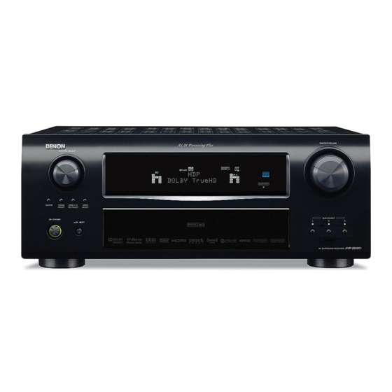
Page 8: Display
Display Q4 Q3 Input signal indicators RESTORER indicator This lights when the RESTORER mode is selected. Input signal channel indicators These light when digital signals are input. AL24 indicator This lights when AL24 Processing Plus is activated (vpage 72). Information display The input source name, surround mode, setting values and other HDMI indicator information are displayed here. -
Page 9: Rear Panel
Rear Panel RS-232C connector ···································································(19) AC inlet (AC IN) ········································································ (20) HDMI connectors ···················································· (11, 12, 14, 15) REMOTE CONTROL jacks ························································(19) AC OUTLET ·············································································· (20) VIDEO / S-VIDEO connectors ····································(12 ~ 16, 19) TRIGGER OUT jacks ·································································(19) Digital audio connectors (OPTICAL / COAXIAL)··········· (12 ~ 16) Analog audio connectors (AUDIO) ································... -
Page 10: Remote Control Unit
Remote Control Unit n Main remote control unit (RC-1102) n Sub remote control unit (RC-1106) Signal transmission indicator ··················· (61) Mode select buttons ·································· (61) The time for which the backlight stays on can Quick select / System call buttons ····· (60, 64) be changed (vpage 65 “Setting the Time the Backlight Stays Lit”). -
Page 11: Connections
With some types of connections, certain settings must be made Cables Used for Connections on the AVR-2809CI. For details, refer to the instructions for the respective connection items below. Select the cables according to the equipment being connected. -
Page 12: Video Conversion Function
Video Conversion Function About onscreen displays due to input signals • This function automatically converts various formats of video signals input to the AVR-2809CI into the The method of onscreen display (OSD) varies with the type of video signal input to AVR-2809CI. -
Page 13: Speaker Connections
4 Ω/ohms), the temperature will rise, and the protection circuit might be activated. The power supply • Since “Amp Assign” of AVR-2809CI is set to “ZONE2” by default, audio is not output from the surround will go into the standby state, and the power indicator will flash red at 2 second intervals. -
Page 14: Connecting Equipment With Hdmi Connectors
Dolby TrueHD, Bitstream Blu-ray • When the AVR-2809CI and Blu-ray Disc player / DVD player are connected using an HDMI cable, also DTS-HD connect the AVR-2809CI and monitor using an HDMI cable. • If the connected monitor or Blu-ray Disc player / DVD player only has a DVI-D connector, use an HDMI/ DVI converter cable. -
Page 15: Connecting The Monitor
Connecting the Monitor Connecting the Playback Components Carefully check the left (L) and right (R) channels and the inputs and outputs, and be sure to interconnect • Select the terminal to use and connect the device (vpage 9 “Video Conversion Function”). •... -
Page 16: Record Player
Use a DENON control dock for iPod (ASD-1R, ASD-11R, ASD-3N or Turntable (MM cartridge) CD player ASD-3W sold separately) to connect the iPod to the AVR-2809CI. For instructions on the control dock for iPod settings, refer to the control dock for iPod’s operating instructions. -
Page 17: Tv/Cable Tuner
TV/CABLE Tuner Satellite Receiver Select the terminal to use and connect the device. Select the terminal to use and connect the device. TV tuner DBS / BS tuner When using a coaxial cable for the digital audio connection, make the settings at menu “Input Setup” •... -
Page 18: Connecting The Recording Components
Select the terminal to use and connect the device. Digital video recorder • When recording via the AVR-2809CI, the playback device’s cable must be of the same type as the cable used to connect the AVR-2809CI’s VCR OUT connector. Example: TV IN → S-Video cable : VCR OUT → S-Video cable TV IN →... -
Page 19: Cd Recorder / Md Recorder / Tape Deck
• When recording via the AVR-2809CI, the playback device´s cable on the main remote control unit and select “EXT. IN” or make the must be of the same type as the cable used to connect the AVR- settings at menu “Input Setup”... -
Page 20: External Power Amplifier
External Power Amplifier Antenna Terminals An F-type FM antenna cable plug can be connected directly. n AM loop antenna assembly Power amplifier Remove the vinyl tie and take out Direction of broadcasting station the connection line. AM loop antenna (supplied) Bend in the reverse direction. -
Page 21: Xm Connector
® ® • The AVR-2809CI is an XM Ready receiver. You can receive XM • The AVR-2809CI is a SIRIUS Satellite Radio Ready receiver. You can ® Satellite Radio by connecting to the XM Mini-Tuner and Home Dock receive SIRIUS... -
Page 22: Multi-Zone
(vpage 67 ~ 69). an external controller using the RS-232C • When using an S-Video cable or a video cable for connection between the AVR-2809CI and an input connector, perform the operation below device, connect to the video connectors. -
Page 23: Connecting The Power Cord
Wait until all connections have been completed before connecting the power cord. With the AVR-2809CI, settings and operations for most functions can be performed by operating while looking at the menus displayed on Symbols used to indicate buttons in this manual Connection to the AC outlets the monitor screen. -
Page 24: Example Of Display Of Default Values
Example of Display of Default Examples of On-screen Display and Front Display Values Some typical examples are described below. GFront displayH GOn-screen displayH In lists of selectable items or adjustable ranges, the item Screen title surrounded by a border is the default value. MENU *MENU 1.Auto Setup... -
Page 25: Menu Map
Menu Map Auto Setup (vpage 23 ~ 26) MENU n Start Menu n Parameter Check 1.Auto Setup • Step 1: Speaker Detection • Speaker Confi guration Check 2.Manual Setup • Step 2: Measurement • Distance Check 3.Input Setup • Step 3: Calculation •... -
Page 26: Preparations
Auto Setup ® • Audyssey MultEQ XT automatically measures the acoustical Preparations problems in the listening environment to create the best audio Symbols used to indicate buttons in this manual experience for your home theater. Button located on both the main unit Connect the included calibrated setup microphone to •... -
Page 27: Auto Setup
• Loud test sounds may be played during Audyssey MultEQ XT • Do not disconnect the setup microphone until the auto setup Since “Amp Assign” of AVR-2809CI is set to “ZONE2” by default, automatic speaker setup. This is part of normal operation. If there procedure is completed. - Page 28 Step 2 : Measurement Step 3 : Calculation Step 4 : Check F Menu screen F F Menu screen F F Menu screen F Auto Setup Auto Setup Auto Setup Audyssey MultEQ XT Audyssey MultEQ XT Audyssey MultEQ XT Auto Setup Step2:Measurement Step3:Calculation Step4:Check...
-
Page 29: Parameter Check
• The front L speaker was not properly Cancel Speaker :None detected. The auto setup measurement results are stored in the AVR-2809CI. Retry Cancel q Select “Store 0”, then press • “Storing Please wait ... ” is displayed on the on-screen display •... -
Page 30: Manual Setup
5.Information 4.Zone Setup 5.Option Setup Since “Amp Assign” of AVR-2809CI is set to “ZONE2” by default, audio is not output from the surround back speakers. When using the surround back speakers with MAIN ZONE, change the “Amp Assign” setting to “7.1ch” (vpage 32). -
Page 31: Subwoofer Setup
d Distance f Channel Level • Select “Large” or “Small” not according to the physical size of the Set distance from listening position to speakers. Adjust channel levels to obtain equal volume from all speakers. speaker but according to the low frequency reproduction capabilities Before making the settings, measure the distance from the based on the frequency set at “Crossover Frequency”... -
Page 32: Crossover Frequency
h Front Speaker Setup a Color Space • When the menu “Speaker Configuration” – “Surround Back Select front speakers to use for each surround mode. Make settings for output color space. Speaker” setting (vpage 27) is set to “1spkr”, the surround back speaker display is set to “SB”. -
Page 33: Hdmi Audio Out
Subwoofer Audio Setup f HDMI Audio Out Select subwoofer use. Select HDMI audio output device. Make settings for audio playback. [Selectable items] [Selectable items] F Menu screen F : Select subwoofer use. : Use speakers connected to receiver for audio playback. 2.Manual Setup 2-3.Audio Setup Subwoofer Mode... -
Page 34: Dolby Digital Setup
Adjust CH d Dolby Digital Setup g EQ Preset q S elect speaker adjustment method. Set dynamic range for downmix playback of Dolby Digital Set MultEQ XT related settings and Manual EQ beforehand. [Selectable items] sources. Each CH : Adjust tonal quality for each speaker separately. EQ Customize [Selectable items] L/R CH... -
Page 35: Option Setup
Option Setup When using speakers that cannot satisfactorily play low frequencies, “VAR” is fixed when a power amplifier is assigned to the ZONE2 or Make various other settings. distortion of the bass sound can be reduced by setting “HPF” to ZONE3 output channel at menu “Manual Setup”... -
Page 36: Volume Control
Master Volume d Source Delete Master volume display during adjustment. For details, see “Amp Assign / Multi-zone Connections and Operations” Remove input sources that are not used from the display. (vpage 67, 68). [Selectable items] [Selectable items] : Turn display on. : Use this source. -
Page 37: Quick Select Name
Default g Quick Select Name A0 Setup Lock Reset the settings to the default values. Change the Quick Select name. Protect settings from inadvertent change. Up to 16 characters can be input. [Selectable items] [Input characters] j Remote ID Setup : Turn protection on. -
Page 38: Input Setup
Input Setup Use this procedure to select the input source and make the settings n PHONO related to playing input sources. Symbols used to indicate buttons in this manual This menu is for “PHONO”. Button located on both the main unit n TUNER (AM/FM) F Menu screen F BUTTON... -
Page 39: Settings Related To Playing Input Sources
Changing the input source within Input Setup NOTE • It is not possible to select HDMI input signals. If you set “Block Presets” to “Skip”, you can skip the preset memory 3.Input Setup Press u to align the • When playing HDMI video input signals, the analog video signal blocks (A to G). -
Page 40: Input Mode
Resolution Aspect [Input source] CD DVD HDP TV/CBL Make settings for resolution of HDMI video output signal. This sets the aspect ratio when outputting 480i/576i or 480p/576p V.AUX SIRIUS input signals from the HDMI output connector. [Input source] DVD HDP TV/CBL [Selectable items] [Input source] DVD HDP TV/CBL V.AUX... -
Page 41: Rename
Mode” to “Digital”. j Source Level [Selectable items] • When the AVR-2809CI and monitor are connected with an HDMI Corrects the playback level of the selected input source’s audio 1-RCA cable, if the monitor is not compatible with HDMI audio signal : Assign component video 1 input connector. -
Page 42: L Ipod
[Selectable items] connected to the VCR (iPod) connector. Check the XM and SIRIUS radio reception sensitivity. • Even if “iPod Dock” is set to “Assign”, if AVR-2809CI and control Unlock : Do not lock selected channel(s). dock for iPod are not connected, the input is used as the normal input source. -
Page 43: Surround Modes
Surround Modes Select the mode to suit the source q Standard Playback Symbols used to indicate buttons in this manual Select the “Cinema”, “Music”, “Game” and “Pro Logic” modes at Button located on both the main unit This is the mode for enjoying surround sound according to the menu “Parameter”... -
Page 44: Playing Multi-Channel Sources (Dolby Digital, Dts, Etc.)
Can also be selected by pressing z1 : This is displayed when the input signal is “DTS-ES Matrix 6.1” and the AVR-2809CI’s “AFDM” setting is set to “ON”. z3: When playing sources recorded in monaural in the MONO MOVIE z2 : This is displayed when the input signal is “DTS-ES Discrete... -
Page 45: Stereo Playback
Stereo Playback Parameter Selecting the mode DIRECT/STEREO Select by press Adjusting the parameters Symbols used to indicate buttons in this manual [Selectable items] Button located on both the main unit MENU Press BUTTON STEREO and the remote control unit The menu is displayed. <BUTTON>... -
Page 46: Surround Parameter
F Menu screen F Dynamic Range Control Surround Parameter 4.Parameter Compress dynamic range (difference between loud and soft sounds). Adjust surround sound parameters. 1.Surround Parameter [Selectable items] Auto High 2.Tone The parameters (items) which can be adjusted differ 3.Audyssey Settings 4.RESTORER depending upon the following conditions. - Page 47 A dopt “7.1ch” for the “Amp Assign” setting. The default setting for the Amp Assign mode of AVR-2809CI • is “ZONE2” . w A dopt a setting other than “OFF” for the “SB CH Out” setting of “Surround Parameter”.
-
Page 48: Tone
A5 SB CH Out Tone Audyssey Settings (Selectable displays during 2-channel source playback.) Adjust the tonal quality of the sound. Select MultEQ XT, Dynamic EQ and Dynamic Volume. Determine whether to use surround back speakers. [Selectable items] A8 Tone Control S1 MultEQ XT : The surround back channel signal is played. - Page 49 S2 Dynamic EQ S3 Dynamic Volume S4 Setting Audyssey Dynamic EQ solves the problem of deteriorating sound Audyssey Dynamic Volume solves the problem of large variations in Can be set when “Dynamic Volume” is set to “ON”. quality as volume is decreased by taking into account human volume level between television programs, commercials, and between Set Dynamic Volume effect.
-
Page 50: Restorer
RESTORER Night Mode Audio Delay This function restores compressed audio signals to how they Optimized setting for late-night listening. Compensate for mismatched timing between video and audio. were before compression and corrects the sense of volume of Set the dynamic range compression of the output audio. Delay audio. -
Page 51: Information
Information Status Audio Input Signal Symbols used to indicate buttons in this manual Shows information about current settings. Shows information about audio input signals. Button located on both the main unit BUTTON and the remote control unit F Menu screen F <BUTTON>... -
Page 52: Hdmi Information
HDMI Information Auto Surround Mode Preset Station Shows information about HDMI input signals and monitor. Shows information about auto surround mode settings. Shows information about preset stations. The surround mode for which the last memory function was used F Menu screen F F Menu screen F for the different input signal types is displayed. -
Page 53: Preparations
Playback Operations During Playback Preparations Symbols used to indicate buttons in this manual Button located on both the main unit Adjusting the Master Volume BUTTON and the remote control unit Turning the Power On <BUTTON> Button only on the main unit <MASTER VOLUME>... -
Page 54: Playing Video And Audio Equipment
Playing Video and Audio Symbols used to indicate buttons in this manual • If the desired station cannot be tuned in with auto tuning, tune it in Equipment Button located on both the main unit manually. BUTTON and the remote control unit •... -
Page 55: Listening To Preset Stations
XM Ready ® Subscription Listening to Preset Stations Listening to XM Satellite Radio Once you have installed the XM Mini-Tuner Home Dock, inserted the Programs Operation on the Main Unit XM Mini-Tuner, connected the XM Mini-Tuner Home Dock to your XM Ready®... -
Page 56: Checking The Xm Signal Strength And Radio
Presetting Radio Channels Checking the XM Signal Strength and Symbols used to indicate buttons in this manual (Preset Memory) Radio ID Button located on both the main unit BUTTON Your favorite broadcast channels can be preset so that you can and the remote control unit <SOURCE SELECT>... -
Page 57: Searching Categories
Searching Categories Basic Operation The strength of both the SIRIUS satellite and terrestrial signals can be <SOURCE SELECT> [SAT TU 1] Press Either turn or press checked at menu “Input Setup” – “Antenna Aiming” (vpage 39). (AMP mode) to select “SIRIUS”. Presetting Radio Channels When using the main remote control unit to operate, Channel category... -
Page 58: Searching Categories
[6], [7], Make the necessary preparations. [1], [2] • “UPDATING” is displayed while the encording code is being q S et the iPod in the DENON control dock for iPod. [SEARCH] updated. (vSee the control dock for iPod’s operating instructions.) •... -
Page 59: Listening To Music
• With the default settings, the iPod can be used connected to the MENU : ”Input Setup” – ”iPod” – “Repeat” (vpage 40) • DENON will accept no responsibility whatsoever for any loss of iPod VCR (iPod) connector. Shuffl ing playback data. -
Page 60: Other Operations And Functions
Other Operations and Functions Other Operations Recording on an External Equipment Symbols used to indicate buttons in this manual (REC OUT mode) Button located on both the main unit BUTTON You can listen to one program source while recording a different and the remote control unit Playing Super Audio CD program source. -
Page 61: Convenient Functions
<SOURCE • To cancel, press , then turn • When you want to listen to TV audio by AVR-2809CI, connect optical CBL” by setting “Input Setup” – “Assign” – “HDMI In” in the menu. SELECT> until “ZONE2 Source” is displayed. -
Page 62: Channel Level
HDMI, or an increase in equipment. (o: front, p: rear) NOTE When you power off AVR-2809CI, the HDMI control function does not operate. Either power on or set to standby. • The fader function does not affect the subwoofer. -
Page 63: Quick Select Function
Quick Select Function Last Function Memory With this function, the currently playing input source, surround This stores the settings as they were directly before the standby mode, MultEQ XT settings and volume can be stored in the mode was set. memory. -
Page 64: Remote Control Unit Operations
• In the AMP, TUNER and iPod modes, when the remote ID is : Blu-ray Disc player / Presetting : SIRIUS / XM set, the AVR-2809CI can be used independently even in an DVD player (Recorder) / CD player (Recorder) environment containing multiple DENON amplifiers. - Page 65 Functions of Buttons by Component EL Display EL Display MODE SELECTOR iPod Device Mode [MODE [1], DVD player Blu-ray Disc CD player SELECTOR] Device operated DVD recorder CD recorder Video deck TAPE iPod [8 9], (Default setting) player (Default setting) [6 7], [3], Playback Playback...
- Page 66 EL Display EL Display MODE SELECTOR Satellite Receiver / Cable TV Device Mode [MODE [1], Device operated TV (HITACHI) TV (SONY) SELECTOR] [8 9], [6 7], [3], [2], Punch through Punch through Punch through Punch through [SOURCE ON], [SOURCE OFF] SOURCE ON Power on Power on...
-
Page 67: Setting The Remote Id
Press and hold in for at least 3 seconds. [RC SETUP] If your AV devices are of a brand other than DENON or if they The signal transmission indicator flashes twice and the setting cannot be operated with the preset memory function, their is completed. -
Page 68: System Call Function
Signal transmission [MODE SELECTOR] Press the buttons you want to register in the same Press for the device you want to indicator AMP] sequence as the operations you want to perform. punch through (DVD or VCR). [ DVD] The signal transmission indicator lights when a button is [MODE pressed. -
Page 69: Adjusting The Backlight's Brightness
System Call Function Sub Remote Control Unit Adjusting the Backlight’s Brightness [RC SETUP] Press and hold in for at least 3 seconds. The display’s brightness can be adjusted in 5 steps. (RC-1106) The signal transmission indicator flashes twice. (Default: Step 3) The sub remote control unit (RC-1106) included with the AVR- [RC SETUP] Press... -
Page 70: Amp Assign / Multi-Zone Connections And Operations
ZONE2 Multi-zone Settings with the Amp Assign Function ZONE3 ZONE2/3-MONO The amp assign function lets you assign the amplifiers for the different channels built into the AVR-2809CI (MONO) (MONO) to the speaker outputs for the different zones. Select the desired playback environment from among “Setting 1” to “Setting 3”, then set the corresponding “Amp Assign”... -
Page 71: Multi-Zone Settings And Operations With Zone Output
Monitor terminals. Power amplifier Setting 3 : Blu-ray Disc player / ZONE2 AVR-2809CI Making bi-amp connections for the FL and FR channels in the MAIN ZONE DVD player video output and conducting 5.1-channel playback Input (switching with other modes not possible) -
Page 72: Multi-Zone Operations
Multi-zone Operations Turning off the Sound Temporarily Symbols used to indicate buttons in this manual Button located on both the main unit In the zone mode for which you want to mute the sound, press BUTTON [MUTE] and the remote control unit Turning the Power On and Off <BUTTON>... -
Page 73: Other Information
Other Information Number of surround back speakers w Setting for primarily watching movies using diffusion type About Speaker Installation speakers for the surround speakers We recommend using 2 speakers. For the greatest sense of surround sound envelopment, diffuse When using dipolar speakers in particular, be sure to use 2 speakers. radiation speakers such as bipolar types, or dipolar types, provide Surround back speakers a wider dispersion than is possible to obtain from a direct radiating... - Page 74 It is fully The AVR-2809CI is equipped with a digital signal processing circuit The surround channel signals are converted into stereo and full band compatible with conventional products, including conventional DTS...
- Page 75 SURROUND Technology and other US and World Wide Patents AL24 Processing for All Channels Pending technology. DENON has further developed its proprietary AL24 Processing, an “Neural” and “Neural Audio” and “Neural Surround” are analog waveform reproduction technology, to support the 192-kHz trademarks of Neural Audio Corporation.
-
Page 76: Surround Modes And Parameters
Surround Modes and Parameters Signals and adjustability in the different modes Channel output Parameter (default values are shown in parentheses) Surround mode Surround Surround D. Comp AFDM Front L/R Center Subwoofer SB CH Out Cinema EQ. Mode Room Size Level Delay time Subwoofer Back L/R... - Page 77 Signals and adjustability in the different modes Parameter (default values are shown in parentheses) Surround mode NEO:6 MUSIC Dynamic PRO LOGIC g/gx MUSIC mode only EXT. IN only Tone Night Mode Dynamic EQ mode only MultEQ XT Volume RESTORER (NOTE6) (NOTE6) (NOTE7) (NOTE8)
- Page 78 Differences in Surround Mode Names Depending on the Input Signals Input signals Button DTS-HD DOLBY DOLBY DIGITAL SACD Linear DTS-HD DTS ES DTS ES DOLBY DOLBY Note Linear DTS-HD DOLBY DOLBY DOLBY DOLBY Surround mode ANALOG High DSCRT MTRX DOLBY DIGITAL DIGITAL Master...
- Page 79 Button Input signals DTS-HD DOLBY DOLBY DIGITAL SACD Linear DTS-HD DTS ES DTS ES DOLBY DOLBY Note Linear DTS-HD DOLBY DOLBY DOLBY DOLBY Surround mode ANALOG High DSCRT MTRX DOLBY DIGITAL DIGITAL Master DIGITAL DIGITAL DIGITAL DIGITAL (multi (multi Resolution (With (With (5.1ch)
- Page 80 Relationship Between Video Signals and Monitor Output Video Input signals Monitor output Video S-VIDEO Input signals Monitor output convert HDMI COMPONENT S-VIDEO VIDEO HDMI COMPONENT S-VIDEO VIDEO convert MONITOR OUT HDMI COMPONENT S-VIDEO VIDEO HDMI COMPONENT S-VIDEO VIDEO — VIDEO VIDEO VIDEO VIDEO...
-
Page 81: Troubleshooting
Set does not • External noise or interference is • Reset the microprocessor. power indicator • Please re-install AVR-2809CI in a – operate properly. causing the set to malfunction. will flash in red place having good ventilation. - Page 82 • Blu-ray Disc player / DVD player • Use a DTS-compatible player. – is not compatible with DTS sound playback. GAudioH • The AVR-2809CI’s “Decode • Set to the “Auto” or “DTS” Symptom Cause Countermeasure Page Mode” setting is set to “PCM”.
- Page 83 • Check the connections. 11 ~ 16, 19 HDMI audio • The “Manual Setup” – “HDMI • Set to “Amp”. appears. AVR-2809CI and monitor are signals are not Setup” – “HDMI Audio Out” faulty. output from setting is set to “TV”.
- Page 84 XM Mini-Tuner Dock or the XM the XM Mini-Tuner dock cable is displayed. Mini-Tuner dock is not connected connected to the AVR-2809CI. ”ANTENNA • The antenna is not connected. • Check that the connections are to the AVR-2809CI. ERROR” is correct.
-
Page 85: Specifications
Specifications Audio section Tuner section [FM] [AM] • Power amplifier (note: µV at 75 Ω/ohms, 0 dBf = 1 x 10 Rated output: Front (A, B): Receiving Range: 87.5 MHz ~ 107 .9 MHz 520 kHz ~ 1710 kHz 115 W + 115 W (8 Ω/ohms, 20 Hz ~ 20 kHz with 0.08 % T.H.D.) Usable Sensitivity: 1.0 µV (11.2 dBf) 18 µV... - Page 86 00477, 00877, 01510, 01877 Bush 40388 40420 00144, 00237 Skyworth 01464 Cairn 40157 Musical Fidelity 40393 Denon SAT Tuner Gehua 00476 Sony 01006, 01460 California Audio Labs 40029, 40303 Myryad 40157 52271 (ID1), 52272 (ID2), General Instrument 00003, 00276, 00476 Sprucer...
- Page 87 TaeKwang 20439 Viewsonic 01272, 01329 Axis 01111 Digiality 01685 Tandberg 20109 B@ytronic 01412 Vizio 01126 Digifusion 01645, 01743 Denon 40766, 42868 Teac 20280, 20283, 20308, 20309 Base 01718 Voodoo 01272 Digihome 01284 40053, 40420 Technics 20229 Beko 00455 Xbox 01805...
- Page 88 00123, 00173, 00200, 00249, Elap 00713, 01567 Golden Interstar 01283 Micro 00713 Panasat 00615, 00879, 01333, 01433 00394, 00442, 00480, 00504, 00247, 00455, 00701, 00847, Kathrein Elsat 00713 GoldStar 00394 Micro Elektronic 00713 00658, 00713, 00818, 01221, Panasonic 01304, 01404, 01508, 01526, 01416, 01561, 01567 Elta 00200, 01659...
- Page 89 00853, 00863, 01108, 01109, 00125, 00713, 00820, 00853, Turnsat 00713 Bell ExpressVu 00775 01392 01142, 01206, 01276, 01377, Strong 00879, 01159, 01284, 01300, British Sky Samsung Twinner 00713, 01611 Rebox 01214 01442, 01458, 01570, 01609, 01409, 01626 01175 Broadcasting 01700, 01916 00879, 01162, 01333, 01356 Sagem 01253, 01307...
- Page 90 Clayton 11037 Denko 10264 Amstrad 10217, 10343, 11196 10362, 10371, 10433, 10648, 10668, 10698, 10714, 10778, CMS Hightec 10217 Denon 10145, 10511 Bang & Olufsen 10565 11037, 11982 11037, 11556, 11900, 11982 10017, 10030, 10047, 10054, Denver 10037, 10587 Amtron...
- Page 91 Domeos 10668 Europhon 10037, 10109, 10217 10037, 10163, 10217, 10361 Hanimex 10218 Huanglong 10009 Domland 10394 Evesham 11248 Geloso 10009, 10163, 10374 Hankook 10030, 10178, 10180 Huangshan 10009, 10264, 10817 10009, 10037, 10217, 10361, Dongda 10009 Evolution 11756 Gemini 10047 Huanyu 10217, 10264, 10374, 10817 Hanseatic...
- Page 92 10009, 10163, 10362, 10374, 10009, 10011, 10030, 10036, 10035 Kolster 10037, 10218 Meile 10264, 10817 Luma 11037 10047, 10051, 10053, 10154, 10009, 10030, 10035, 10037, Jensen 10761, 10815, 10817, 11933 Kongque 10009, 10264, 10817 10156, 10170, 10178, 10217, 10037, 10073, 10163, 10217, 10060, 10150, 10154, 10178, Lumatron Memorex...
- Page 93 10011, 10017, 10037, 10178, 10011, 10030, 10051, 10060, 10009, 10030, 10036, 10047, 10009, 10208, 10226, 10264, Radialva 10163, 10218 Pilot Shanghai 10180, 10236, 10264, 10433, 10178, 10706 10092, 10093, 10154, 10171, 10817 Orion Sampo Radiola 10037, 10217, 10556 10463, 10556, 10714, 10880, 10178, 10650, 10700, 11755, 10011, 10037, 10109, 10163, Shaofeng...
- Page 94 10000, 10011, 10017, 10036, 10009, 10037, 10264, 10418, 10000, 10001, 10017, 10030, Syntax 11144, 11240, 11331, 11610 Telestar 10009, 10037, 10556 10037, 10053, 10074, 10150, Transonic 10455, 10512, 10587, 10698, 10035, 10037, 10047, 10051, Sony Sysline 10037 Teletech 10009, 10037, 10668, 11037 10154, 10353, 10650, 11100, 10712, 10780 10054, 10060, 10093, 10154,...
- Page 95 Zanussi 10163, 10217 Schneider 11982 Orion 30695 Panasonic 10051, 10250 GoldStar 20037, 20480, 21237 10000, 10017, 10030, 10037, 11037 Pacific 30695 Penney 10051 Goodmans 20278, 20352, 20637 10047, 10092, 10093, 10145, Sova 11952 Panasonic 31490 Philips 10037, 10556 Grandin 20278, 20742 Zenith 10171, 10178, 10463, 10812, 11145, 11265, 11904, 11909,...
- Page 96 20352, 20480, 20642, 20742, ITT Nokia 20041, 20104, 20106, 20240 Dell 21972 Genexxa 20000, 20037, 20104, 20278 21137 Toshiba 31045 20037, 20278 Denon 200842, 20081 Go Video 20240, 20432, 20614, 21137 20046 Janeil 20240 20000, 20035, 20037, 20039, Derwent 20041 Brandt...
- Page 97 20041, 20045, 20067, 20081, 20000, 20035, 20037, 20039, 20000, 20035, 20037, 20047, Quelle 20081 Seleco 20037, 20041 20184, 21162 20046, 20047, 20048, 20104, Optimus 20048, 20104, 20162, 20240, Radialva 20037, 20048, 20081 Semp 20045 Memorex 20162, 20209, 20240, 20278, 20432, 21062, 21162, 21262 Kambrook 20037 20348, 20479, 21162, 21237,...
- Page 98 30717, 30723, 30730, 30831, Alba 30713, 30717, 30730, 30783, Bush 20845, 21008, 21145, 21972, 30833, 30884, 31051, 31140, 30490, 30634, 31634, Hewlett Packard 21972 30884, 31140, 31530, 31695 Denon 21996 31367, 31483, 31695, 31832 [32134] Howard Computers 21972 Alco 30790 Tosonic 20278 Byd:sign...
- Page 99 DreamX 31151 Gradiente 30490, 30651 Kansas Technologies 31233, 31530 Maxim 30713, 30872, 31367 Onkyo 30503, 30627, 31769 30833, 31152, 31730 Graetz 30665 Karcher 30783 Maya 31345 Oopla 31158 30651, 30675, 30713, 30730, Gran Prix 30831, 30898 Kawasaki 30790 30690, 30730, 31730 Oppo 31224 Dual...
- Page 100 30789, 30790, 30833, 31483, Skymaster 30730, 30768 Cytron 31347 Telefunken Richmond 31233 Xenius 30790 31832, 31923 Skyworth 30898 Denon 30490 30869 Teletech 30713, 30768 XLogic 30768, 31152, 31228 Sliding 31115 Denver 31056 30672, 30690, 30699, 30713, Tensai 30651, 30690, 30770...
- Page 101 b1 : These preset codes can be recorded in the SAT/CBL mode. Philips 30646, 31158, 31340 DVD preset codes : Ces codes de présélection peuvent être enregistrés en mode SAT/CBL. 32134 30490 Pioneer 30631 Codes préréglés DVD Polaroid 31086 b2 : These preset codes can be recorded in the TV mode. ProVision 31321 : Ces codes de présélection peuvent être enregistrés en mode TV.
- Page 102 Denon Brand Company, D&M Holdings Inc. Printed in Japan 5411 10104 102DA...
Need help?
Do you have a question about the AVR-2809CI and is the answer not in the manual?
Questions and answers