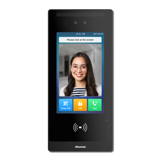
Akuvox E18 Quick Manual
Smart intercom
Hide thumbs
Also See for E18:
- Installation manual (6 pages) ,
- Quick manual (12 pages) ,
- Manual (11 pages)
Advertisement
Table of Contents
Unpacking
Before using the device, check the device model and ensure that the shipped box includes the
following items:
lush-mounting bracket
�
M�x�� Torx head screw
Product Overview
White Light LED
LCD
Card Reader
Flush-mounting boxer
�
ST�x�� crosshead screw
Flush-mounting plate
�
Plastic wall anchor
Infrared LED
Camera
Face-liveness Detection Camera
Photosensitive Sensor
Speaker
E18
�
M�x� crosshead screw
Allen wrench
Advertisement
Table of Contents

Summary of Contents for Akuvox E18
- Page 1 Unpacking Before using the device, check the device model and ensure that the shipped box includes the following items: � lush-mounting bracket Flush-mounting boxer Flush-mounting plate M�x� crosshead screw � � � Allen wrench M�x�� Torx head screw Plastic wall anchor ST�x��...
-
Page 2: Before You Start
Before You Start Tools needed (not included in shipped box) · Cat Ethernet Cable · Crosshead Screwdriver · Electric Drill Voltage and Current Specifications · It is suggested that use PoE or ��VDC �A power adapter to power on device. AWG Sizes and Properties Table Please follow the properly wire data to install device: Power Supply... - Page 3 Use wet cloth clean device surface softly, and then wipe the surface with dry cloth for cleaning the device. �. If there is abnormal situation of the device, including uncommon sound and smell, please power off the device and contact Akuvox Technical Team immediately.
-
Page 4: Installation
Wiring Interface To protect the device from potential damage caused by over-voltage, it is recommended to wire a diode into the circuit. Connect the anode of the diode to the negative cable of the lock, and connect the cathode of the diode to the positive cable of the lock. Installation Step �: Flush-mounting Box Installation Dig out a square hole with dimension ���*���*��mm... - Page 5 Place the flush-mounting box in the hole. Mark six positioning holes of the flush-mounting bracket on the wall. Note:The positioning holes should be marked in the center of the holes. Remove the flush-mounting box. Use an electric drill with a �mm diameter bit to make four holes with ��mm in depth in the marked holes.
- Page 6 Step �: Main Unit Installation As shown in the picture, combine bracket, device, and plate together. Secure them by fixing six M�x� crosshead screws. Lead the wires from the flush-mounting box through the plate, sealing ring, and wiring cover. Connect wires to the corresponding interface as needed (for details, refer to "Wiring Interface").
-
Page 7: Device Test
Do not attempt to modify, alternate, maintain, or repair device by yourself. Akuvox warranty does not apply to damages caused by anyone who is not representative of Akuvox or an Akuvox authorized service provider. Please contact Akuvox Technical Team if the device need to be... - Page 8 Information contained in this document is believed to be accurate and reliable at the time of printing. This document is subject to change without notice, any update to this document can be viewed on Akuvox’ s website: http://www.akuvox- .com © Copyright 2024 Akuvox Ltd. All rights reserved.


Need help?
Do you have a question about the E18 and is the answer not in the manual?
Questions and answers