D-Link DXS-3250 Web/Installation Manual
L2 stackable gigabit mngd. switch with optional 10gig uplinks
Hide thumbs
Also See for DXS-3250:
- Cli manual (466 pages) ,
- Web/installation manual (372 pages) ,
- Web/installation manual (424 pages)

Related Manuals for D-Link DXS-3250


Summary of Contents for D-Link DXS-3250
- Page 1 Web/Installation Guide DXS-3200 Series Product Model : L2 Stackable Gigabit Mngd. Switch with Optional 10Gig Uplinks Release 1 ©Copyright 2005. All rights reserved.
-
Page 2: Table Of Contents
Software Download and Reboot ....................39 Startup Menu Functions ........................ 41 Getting Started........................45 Starting the D-Link Embedded Web Interface................46 Understanding the D-Link Embedded Web Interface..............48 Using Screen and Table Options ....................51 Resetting the Device ........................53 Logging Off from the Device ...................... - Page 3 Table of Contents Configuring Stacking ........................59 Managing Device Information ....................60 Defining the System Description ....................61 Defining Advanced System Settings ..................... 62 Managing Power over Ethernet Devices................63 Defining PoE System Information....................64 Defining PoE Interfaces ......................... 66 Configuring Device Security....................
- Page 4 D-Link DXS-3250/DXS-3227P/DXS-3227 User Guide Defining Multicast Bridging Groups..................... 170 Managing System Files....................... 174 File Management Overview ......................175 Downloading System Files......................17 Uploading System Files ......................177 Activating Image Files ......................... 178 Copying Files ..........................179 Managing System Files....................... 180 Configuring Quality of Service ....................
- Page 5 Managing RMON Statistics ......................257 Appendix A Technical Specifications .................. 264 Appendix B Cables and Connectors .................. 267 Appendix C Troubleshooting....................269 Problem Management .........................270 Troubleshooting Solutions ......................270 Warranty ............................273 Product Registration ........................276 Contacting D-Link Technical Support ..................277 International Offices........................304 Page 4...
-
Page 6: Preface
Interface web pages are easy-to-use and easy-to-navigate. In addition, The D-Link Embedded Web Interface pro- vides real time graphs and RMON statistics to help system administrators monitor network performance. This preface provides an overview to the D-Link Embedded Interface User Guide, and includes the following sec- tions: •... - Page 7 Section 3. Starting and Configuring the Device — Provides step-by-step instructions for the initial device configuration. Using the Embedded Web Interface User Guide This section provides an overview to the D-Link Web System Interface User Guide. The D-Link Web System Inter- face User Guide provides the following sections: •...
-
Page 8: Intended Audience
D-Link DXS-3250/DXS-3227P/DXS-3227 User Guide • Section 16. Managing System Files — Provides information about downloading, uploading, and copying system files. • Section 20. Managing System Logs — Provides information about enabling and defining system logs. • Section 21. Managing Device Diagnostics — Provides information about configuring port mirroring, testing copper and fiber cables, and viewing device health information. - Page 9 Preface Intended Audience Page 8...
-
Page 10: Device Description
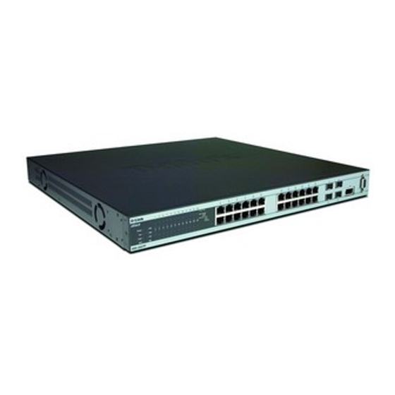
D-Link DXS-3250/DXS-3227P/DXS-3227 User Guide Section 1. Device Description This section contains a description of the D-Link DXS-3250 and D-Link DXS-3227, and contains the following top- ics: • Viewing the Device • Ports Description • Cable Specifications • LED Defiitions •... - Page 11 DXS-3250 Front Panel The D-Link DXS-3250 is a 48 port Gigabit Ethernet Managed Switch. The device contains 48 gigabit network ports and 4 SFP Ports on the front panel for network connectivity, and 2 stacking ports on the back panel.
-
Page 12: Back Panels
(fiber) connections. On the front panel there are the Port activity LEDs on each port with the system LEDs displayed separately. Back Panels The following figure illustrates both the DXS-3250 and DXS-3227 back panels. Figure 3: DXS-3250 and DXS-3227 Back Panel The DES-3010 device back panel is configured as follows: •... -
Page 13: Ports Description
Device Description Ports Description Ports Description This section describes the device ports and includes the following topics: • 1000Base-T Gigabit Ethernet Ports • 100Base-FX Fiber port • SFP Port • RS-232 Console Port 1000Base-T Gigabit Ethernet Ports The device contains a 1000 Base-TX Gigabit port. The port is an RJ-45 port which supports half- and full-duplex mode 10/100/1000 Mbps. -
Page 14: Stacking Ports
D-Link DXS-3250/DXS-3227P/DXS-3227 User Guide Stacking Ports The device provides two stacking HyperG.Link interface ports. One stacking port provides an Up connection, while the second provides a Down stacking connection. A 4X to 4X Infidband Cable is used to connect devices in the stacking configuration. -
Page 15: Cable Specifications
Device Description Cable Specifications Cable Specifications The following table contains the various cable specification for the DXS-3250/DXS-3227P: Table 1: DXS-3250/DXS-3227P Cable Specifications Cab le Typ e D escr ip tio n 1000Base-T UTP Cat. 5e (100 meters max.) UTP Cat. 5 (100 meters max.) EIA/TIA-568B 150-ohm STP (100 meters max.) -
Page 16: Led Defiitions
System — Indicating the device power supply status. Port LEDs 1000Base-T Gigabit Ethernet RJ-45 Port LEDs The LEDs on the two devices are differently indicated. The following figure illustrates the DXS-3250 port LEDs. Figure 5: DXS-3250 1000Base-T Gigabit Ethernet RJ-45 Port LEDs Page 15... -
Page 17: Led Defiitions
Device Description LED Defiitions The DXS-3227 device has the LED indications on a LED panel on the left side of the device. The following figure illustrates the port LEDs. Figure 6: DXS-3227 1000Base-T Gigabit Ethernet RJ-45 Port LEDs The RJ-45 ports on both devices have two LEDs, one for speed, and one for Link /activity. The LED indications are described in the following table: Table 2: 1000Base-T Gigabit Ethernet RJ-45 Port LED Indications... -
Page 18: System Leds
No link is established on the port. System LEDs The two devices have different system LEDs. DXS-3250 The sytstem LEDs on the DXS-3250 device in on the left side of the device. The following figure illustrates the DXS-3250 system LEDs. Figure 8: DXS-3250 System LEDs DXS-3227 The sytstem LEDs on the DXS-3227 device in on the left side of the device. - Page 19 Device Description LED Defiitions The LED indications are described in the following table: Table 4: System LED Indications LED Des cription L ED Des cription I nd i c a t i on Green The device is powered up. The device is not powered up. Indicates a faulty fan.
-
Page 20: Cable, Port, And Pinout Information
D-Link DXS-3250/DXS-3227P/DXS-3227 User Guide Cable, Port, and Pinout Information This section describes the devices physical interfaces and provides information about cable connections. Stations are connected to the device ports through the physical interface ports on the front panel. For each station, the appropriate mode (Half/Full Duplex, Auto Negotiation) is set. -
Page 21: Physical Dimensions
Device Description Physical Dimensions Physical Dimensions The device has the following physical dimensions: • Width: 440 mm (17.32 inch) • Depth: 430mm (16.93 inch) • Height: 45 mm (1.77 inch) Page 20... -
Page 22: Mounting Device
D-Link DXS-3250/DXS-3227P/DXS-3227 User Guide Section 2. Mounting Device This section contains information for installing the device, and includes the following sections: • Preparing for Installation • Installing the Device • Connecting the Device • Rack Installation Page 21... - Page 23 Mounting Device Preparing for Installation Preparing for Installation This section provides an explanation for preparing the installation site, and includes the following topics: • Installation Precautions • Site Requirements • Unpacking Installation Precautions Warnings • The surface on which the switch is placed should be adequately secured to prevent it from becoming unstable and/or falling over.
-
Page 24: Package Contents
Carefully remove the device from the container and place it on a secure and clean surface. Remove all packing material. Inspect the product for damage. Report any damage immediately. If any item is found missing or damaged, please contact your local D-Link reseller for replacement. Page 23... -
Page 25: Installing The Device
Mounting Device Installing the Device Installing the Device The device can be installed on a flat surface or mounted in a rack. This section includes the following topics: • Desktop or Shelf Installation • Rack Installation Desktop or Shelf Installation When installing the switch on a desktop or shelf, the rubber feet included with the device should first be attached. - Page 26 D-Link DXS-3250/DXS-3227P/DXS-3227 User Guide Notes • Disconnect all cables from the unit before mounting the device in a rack or cabinet. • When mounting multiple devices into a rack, mount the devices from the bottom up. To install the device in a rack, perform the following: Place the supplied rack-mounting bracket on one side of the device ensuring the mounting holes on the device line up to the mounting holes on the rack mounting bracket.
- Page 27 Mounting Device Installing the Device Figure 13: Mounting Device in a Rack Secure the unit to the rack with the rack screws (not provided). Fasten the lower pair of screws before the upper pair of screws. This ensures that the weight of the unit is evenly distributed during installation. Ensure that the ventilation holes are not obstructed.
-
Page 28: Connecting The Device
D-Link DXS-3250/DXS-3227P/DXS-3227 User Guide Connecting the Device This section describes how to connect the device, and includes the following sections: • Connecting the Switch to a Terminal • AC Power Connection Connecting the Switch to a Terminal The device is connected to a terminal through an console port on the front panel, which enables a connection to a terminal desktop system running terminal emulation software for monitoring and configuring the device. -
Page 29: Initial Configuration
Section 3. Initial Configuration This section describes the initial device configuration and includes the following topics: • General Configuration Information • Booting the Switch • Stacking Configuration • Configuration Overview • Advanced Configuration • Software Download and Reboot • Startup Menu Functions After completing all external connections, connect a terminal to the device to monitor the boot and other procedures. -
Page 30: Booting The Switch
Initial Configuration Booting the Switch If connecting a port of the switch to the network interface card (NIC) of a terminal that does not support auto-nego- tiation or is not set to auto-negotiation, both the device port and the NIC must be manually set with the Web browser interface or CLI commands to the same speed and duplex mode. - Page 31 D-Link DXS-3250/DXS-3227P/DXS-3227 User Guide Activate the AC power receptacle. When the power is turned on with the local terminal already connected, the switch goes through Power On Self Test (POST). POST runs every time the device is initialized and checks hardware components to determine if the device is fully operational before completely booting.
-
Page 32: Stacking Configuration
Initial Configuration Stacking Configuration Note The following screen is an example configuration.Items such as addresses, versions, and dates may differ for each device. Preparing to decompress... Decompressing SW from image-1 638000 Running from RAM... ********************************************************************* *** Running SW Ver. x.x.x.x Date 11-Jan-200x Time 15:43:13 *** ********************************************************************* HW version is Base Mac address is: 00:00:b0:24:11:80... -
Page 33: Configuration Overview
D-Link DXS-3250/DXS-3227P/DXS-3227 User Guide The Startup menu is displayed and contains the following configuration functions: Startup Menu [1] Download Software [2] Erase Flash File [3] Password Recovery Procedure [4] Enter Diagnostic Mode [5] Set Terminal Baud-Rate [6] Stack menu [7] Back Enter your choice or press 'ESC' to exit: On the Startup menu, press “6”. -
Page 34: Static Ip Address And Subnet Mask
Initial Configuration Configuration Overview • User Name • SNMP Community strings Static IP Address and Subnet Mask IP interfaces can be configured on each port of the device. After entering the configuration command, it is recom- mended to check if a port was configured with the IP address by entering the “show ip interface” command. The commands to configure the device are port specific. -
Page 35: Snmp Community Strings
D-Link DXS-3250/DXS-3227P/DXS-3227 User Guide SNMP Community Strings Simple Network Management Protocol (SNMP) provides a method for managing network devices. Devices sup- porting SNMP run a local software (agent). The SNMP agents maintain a list of variables, used to manage the device. -
Page 36: Advanced Configuration
Initial Configuration Advanced Configuration configure Console# snmp-server community private type Config(config)# rw 11.1.1.2 router exit Config(config)# show snmp Console(config)# Community-String Community-Access IP address ---------------- ---------------- ---------- private readWrite 11.1.1.2 Traps are enabled. Authentication-failure trap is enabled. Trap-Rec-Address Trap-Rec-Community Version ---------------- ------------------ ------- System Contact:... -
Page 37: Receiving An Ip Address From A Bootp Server
D-Link DXS-3250/DXS-3227P/DXS-3227 User Guide -------- ------ --------------- 10.7.1.1 Static Active IP address Interface Type Directed Broadcast ------------- --------- ------- -------- 10.7.1.192/24 VLAN 1 Static Notes: 1. The device configuration does not have to be deleted to retrieve an IP address for the DHCP server. - Page 38 Initial Configuration Advanced Configuration cable for the local terminal only and allows a one-time access to the device from the local terminal with no pass- word entered. Configuring Security Passwords Introduction The security passwords can be configured for the following services: •...
-
Page 39: Software Download And Reboot
D-Link DXS-3250/DXS-3227P/DXS-3227 User Guide When changing a device mode to enable, enter “jones”. Configuring an Initial HTTP Password To configure an initial HTTP password, enter the following commands: ip http authentication local Console(config)# username admin password level Console(config)# user1 Configuring an initial HTTPS Password... -
Page 40: Software Download Through Tftp Server
Initial Configuration Software Download and Reboot Software Download Through TFTP Server This section contains instructions for downloading device software (system and boot images) through a TFTP server. The TFTP server must be configured before downloading the software. The switch boots and runs when decompressing the system image from the flash memory area where a copy of the system image is stored. -
Page 41: Startup Menu Functions
D-Link DXS-3250/DXS-3227P/DXS-3227 User Guide Enter the command “reload”. The following message is displayed: Console# reload This command will reset the whole system and disconnect your current session.Do you want to continue (y/n)[n]? Enter “Y” to reboot the switch. Boot Image Download Loading a new boot image from the TFTP server and programming it into the flash updates the boot image. -
Page 42: Download Software
Initial Configuration Startup Menu Functions The Startup menu is displayed and contains the following configuration functions: Startup Menu [1] Download Software [2] Erase Flash File [3] Password Recovery Procedure [4] Enter Diagnostic Mode [5] Set Terminal Baud-Rate [6] Stack menu [7] Back Enter your choice or press 'ESC' to exit: The following sections describe the Startup menu options. -
Page 43: Password Recovery
D-Link DXS-3250/DXS-3227P/DXS-3227 User Guide The following message is displayed. Write Flash file name (Up to 8 characters, Enter for none.):config File config (if present) will be erased after system initialization ========Press Enter To Continue ======== Enter as the name of the flash file. The configuration is erased and the device reboots. - Page 44 Initial Configuration Startup Menu Functions From the Stack menu, press “2”. The following message is displayed: Enter your choice or press 'ESC' to exit: Stacking Ports List - Add stacking ports (valid range 1-48, 49 - 50) use 'q' quit. Select the port and press <Enter>.
-
Page 45: Getting Started
D-Link DXS-3250/DXS-3227P/DXS-3227 User Guide Section 4. Getting Started This section provides an introduction to the user interface, and includes the following topics: • Starting the D-Link Embedded Web Interface • Understanding the D-Link Embedded Web Interface • Using Screen and Table Options •... -
Page 46: Starting The D-Link Embedded Web Interface
Notes • Disable the popup blocker before beginning device configuration using the EWS. This section contains information on starting the D-Link Embedded Web interface. To access the D-Link user interface: Open an Internet browser. Ensure that pop-up blockers are disabled. If pop-up blockers are enable, edit, add, and device information messages may not open. - Page 47 D-Link DXS-3250/DXS-3227P/DXS-3227 User Guide Notes • The screen captures in this Guide represent the 48 port device. The Web pages in the 24 port device may vary slightly. Figure 15: D-Link Embedded Web Interface Home Page Page 47...
-
Page 48: Understanding The D-Link Embedded Web Interface
Understanding the D-Link Embedded Web Interface Understanding the D-Link Embedded Web Interface The D-Link Embedded Web Interface Home Page contains the following views: • Port LED Indicators — Located at the top of the home page, the port LED indicators provide a visual repre- sentation of the ports on the D-Link front panel. -
Page 49: Device Representation
EWS. This section provides the following additional information: • Device Representation — Provides an explanation of the D-Link user interface buttons, including both man- agement buttons and task icons. • Using the D-Link Embedded Web Interface Management Buttons — Provides instructions for adding, modifying, and deleting configuration parameters. - Page 50 Getting Started Understanding the D-Link Embedded Web Interface Using the D-Link Embedded Web Interface Management Buttons Configuration Management buttons and icons provide an easy method of configuring device information, and include the following: Table 8: D-Link Web Interface Configuration Buttons...
-
Page 51: Using Screen And Table Options
• Deleting Configuration Information Adding Configuration Information User-defined information can be added to specific D-Link Web Interface pages, by opening a new Add page. To add information to tables or D-Link Web Interface pages: Open an D-Link Web Interface page. -
Page 52: Deleting Configuration Information
Modify the fields. Click . The fields are modified, and the information is saved to the device. Deleting Configuration Information Open The D-Link Embedded Web Interface page. Select a table row. Select the Remove checkbox. Click . The information is deleted, and the device is updated. -
Page 53: Resetting The Device
D-Link DXS-3250/DXS-3227P/DXS-3227 User Guide Resetting the Device The Reset page enables resetting the device from a remote location. Note To prevent the current configuration from being lost, save all changes from the running configuration file to the startup configuration file before resetting the device. For instructions, see Copying Files. -
Page 54: Logging Off From The Device
. The device is reset, and a prompt for a user name and password is displayed. Enter a user name and password to reconnect to the web Interface. Logging Off from the Device Click . The Logout Page opens. Figure 22: Logout Page Click . The D-Link Embedded Web Interface Home Page closes. Page 54... -
Page 55: Managing Stacking
D-Link DXS-3250/DXS-3227P/DXS-3227 User Guide Section 5. Managing Stacking Stacking provides multiple switch management through a single point as if all stack members are a single unit. All stack members are accessed through a single IP address through which the stack is managed. The stack is can be managed from the following: •... -
Page 56: Understanding The Stack Topology
Managing Stacking Understanding the Stack Topology Understanding the Stack Topology Stacked devices operate in a Ring topology. A Ring topology is where all devices in the stack are connected to each other forming a circle. Each stacked device accepts data and sends it to the device to which it is physically connected. -
Page 57: Removing And Replacing Stacking Members
D-Link DXS-3250/DXS-3227P/DXS-3227 User Guide Notes • If two members are discovered with the same Unit ID the stack continues to function, however only the unit with the older join time joins the stack. A message is sent to the user, notifying that a unit failed to join the stack. -
Page 58: Exchanging Stacking Members
Managing Stacking Exchanging Stacking Members • Units toggle between Stacking Mode and Stand-alone Mode Each time the system reboots, the Startup Configuration file in the Master unit is used to configure the stack. If a stack member is removed from the stack, and then replaced with a unit with the same Unit ID, the stack member is configured with the original device configuration. -
Page 59: Configuring Stacking
D-Link DXS-3250/DXS-3227P/DXS-3227 User Guide Configuring Stacking The Stack Page allows network managers to either reset the entire stack or a specific device. Device configuration changes that are not saved before the device is reset are not saved. If the Stacking Mas- ter is reset, the entire stack is reset. -
Page 60: Managing Device Information
Managing Device Information Section 6. Managing Device Information This section contains information for setting general system information, and includes the following sections: • Defining the System Description • Defining Advanced System Settings Page 60... -
Page 61: Defining The System Description
D-Link DXS-3250/DXS-3227P/DXS-3227 User Guide Defining the System Description The System Description Page contains parameters for configuring general device information, including the sys- tem name, location, and contact, the system MAC Address, System Object ID, System Up Time, System IP and MAC addresses, and both software and hardware versions. -
Page 62: Defining Advanced System Settings
Managing Device Information Defining Advanced System Settings Defining Advanced System Settings The Mode Page allows network managers to enable Jumbo Frames on the device. Jumbo Frames enable the transportation of identical data in fewer frames. This ensures less overhead, lower processing time, and fewer interruptions. -
Page 63: Managing Power Over Ethernet Devices
D-Link DXS-3250/DXS-3227P/DXS-3227 User Guide Section 7. Managing Power over Ethernet Devices Power over Ethernet (PoE) provides power to devices over existing LAN cabling, without updating or modifying the network infrastructure. Power over Ethernet removes the necessity of placing network devices next to power sources. -
Page 64: Defining Poe System Information
Managing Power over Ethernet Devices Defining PoE System Information Defining PoE System Information The PoE Properties Page contains system PoE information for enabling PoE on the device, monitoring the current power usage, and enabling PoE traps.To enable PoE on the device: Click the System >... - Page 65 D-Link DXS-3250/DXS-3227P/DXS-3227 User Guide Define the System Usage Threshold field. Check the Traps checkbox. Click . The system PoE parameters are defined, and the device is updated. Page 65...
-
Page 66: Defining Poe Interfaces
Managing Power over Ethernet Devices Defining PoE Interfaces Defining PoE Interfaces The Power Over Ethernet Interface Page contains information for configuring PoE interfaces, including the inter- face PoE operation status and the interface’s power consumption. To define PoE for interfaces: Click the System >... - Page 67 D-Link DXS-3250/DXS-3227P/DXS-3227 User Guide – Fault — Indicates that the device has detected a fault on the powered device. For example, the powered device memory could not be read. • Priority Level — Determines the port priority if the power supply is low. The port power priority is used if the power supply is low.
-
Page 68: Defining Poe Interfaces
Managing Power over Ethernet Devices Defining PoE Interfaces • Overload Counter — Indicates the total power overload occurrences. • Short Counter — Indicates the total power shortage occurrences. • Denied Counter — Indicates times the powered device was denied power. •... -
Page 69: Configuring Device Security
D-Link DXS-3250/DXS-3227P/DXS-3227 User Guide Section 8. Configuring Device Security This section provides access to security pages that contain fields for setting security parameters for ports, device management methods, users, and server security. This section contains the following topics: • Configuring Management Security •... -
Page 70: Configuring Management Security
Configuring Device Security Configuring Management Security Configuring Management Security This section provides information for configuring device management security. This section includes the following topics: • Configuring Authentication Methods • Configuring Passwords Configuring Authentication Methods This section provides information for configuring device authentication methods. This section includes the topics: •... -
Page 71: Defining Access Profiles
D-Link DXS-3250/DXS-3227P/DXS-3227 User Guide Defining Access Profiles Access profiles are profiles and rules for accessing the device. Access to management functions can be limited to user groups. User groups are defined for interfaces according to IP addresses or IP subnets. Access profiles con- tain management methods for accessing and managing the device. - Page 72 Configuring Device Security Configuring Management Security – Unchecked — Maintains the access profiles. Click . The Add Access Profile Page opens: Figure 29: Add Access Profile Page In addition to the fields in the Access Profile Page, the Add Access Profile Page contains the following fields: •...
- Page 73 D-Link DXS-3250/DXS-3227P/DXS-3227 User Guide – Source IP Address — Defines the interface source IP address to which the access profile applies. The Source IP Address field is valid for a subnetwork. Define the Access Profile Name, Rule Priority, Management Method, Interface, Source IP Address, Network Mask or Prefix Length, and Action fields.
-
Page 74: Defining Profile Rules
Configuring Device Security Configuring Management Security Defining Profile Rules Access profiles can contain up to 128 rules that determine which users can manage the switch module, and by which methods. Users can also be blocked from accessing the device. Rules are composed of filters including: •... - Page 75 D-Link DXS-3250/DXS-3227P/DXS-3227 User Guide • Management Method — Defines the management method for which the rule is defined. Users with this access profile can access the device using the management method selected. The possible field values are: – All — Assigns all management methods to the rule.
- Page 76 Configuring Device Security Configuring Management Security Click . The profile rule is added to the access profile, and the device is updated. To modify a Profile Rule: Click Security > Management Security > Authentication > Access Profile. The Access Profile Page opens.
-
Page 77: Defining Authentication Profiles
D-Link DXS-3250/DXS-3227P/DXS-3227 User Guide Defining Authentication Profiles Authentication profiles allow network administrators to assign authentication methods for user authentication. User authentication can be performed either locally or on an external server. User authentication occurs in the order the methods are selected. If the first authentication method is not available, the next selected method is used. - Page 78 Configuring Device Security Configuring Management Security Click . The Add Authentication Profile Page opens. Figure 34: Add Authentication Profile Page Define the Profile Name and Authentication Methods fields. Click . The authentication profile is defined, and the device is updated. Page 78...
- Page 79 D-Link DXS-3250/DXS-3227P/DXS-3227 User Guide To modify an authentication profile: Click System > Management Security > Authentication > Authentication Profiles. The Authentication Profile Page opens. Click . The Authentication Profile Settings Page opens: Figure 35: Authentication Profile Settings Page Select an authentication method from the Optional Methods list.
-
Page 80: Mapping Authentication Methods
Configuring Device Security Configuring Management Security Mapping Authentication Methods After authentication profiles are defined, they can be applied to management access methods. For example, con- sole users can be authenticated by Authentication Profile List 1, while Telnet users are authenticated by Authenti- cation Method List 2. - Page 81 D-Link DXS-3250/DXS-3227P/DXS-3227 User Guide – Local — Indicates that Authentication occurs locally. – RADIUS — Indicates that Authentication occurs at the RADIUS server. – Line — Indicates that Authentication uses a line password. – Enable — Indicates that Authentication uses an Enable password.
-
Page 82: Defining Radius Settings
Configuring Device Security Configuring Management Security Defining RADIUS Settings Remote Authorization Dial-In User Service (RADIUS) servers provide additional security for networks. RADIUS servers provide a centralized authentication method for web access. The default parameters are user-defined, and are applied to newly defined RADIUS servers. If new default param- eters are not defined, the system default values are applied to newly defined RADIUS servers. - Page 83 D-Link DXS-3250/DXS-3227P/DXS-3227 User Guide • Priority — Displays the RADIUS server priority. The possible values are 1-65535, where 1 is the highest value. The RADIUS server priority is used to configure the server query order. • Authentication Port — Identifies the authentication port. The authentication port is used to verify the RADIUS server authentication.
- Page 84 Configuring Device Security Configuring Management Security Define the Host IP Address, Priority, Authenticated Port, Timeout for Reply, Dead Time, and Usage Type fields. Click . The RADIUS server is added, and the device is updated. To edit RADIUS Server Settings: Click System >...
- Page 85 D-Link DXS-3250/DXS-3227P/DXS-3227 User Guide Defining TACACS+ Authentication Terminal Access Controller Access Control System (TACACS+) provides centralized security user access valida- tion. The sytem supports up-to 4 TACACS+ servers. TACACS+ provides a centralized user management system, while still retaining consistency with RADIUS and other authentication processes.
- Page 86 Configuring Device Security Configuring Management Security • Priority — Defines the order in which the TACACS+ servers are used. The field range is 0-65535. The default is 0. • Source IP Address — Defines the device source IP address used for the TACACS+ session between the device and the TACACS+ server.
- Page 87 D-Link DXS-3250/DXS-3227P/DXS-3227 User Guide To edit a TACACS+ server settings: Click Security > Management Security >Authentication > TACACS+. The TACACS+ Page opens. Select TACACS+ server entry. Click . The Add TACACS+ Host Page opens. Figure 42: TACACS+ Host Settings Page Define the Priority, Source IP Address, Key String, Authentication Port, Timeout for Reply, and Single Con- nection fields.
-
Page 88: Configuring Passwords
Configuring Device Security Configuring Management Security Configuring Passwords This section contains information for defining device passwords, and includes the following topics. • Defining Local Users • Defining Line Passwords • Defining Enable Passwords Defining Local Users define users, passwords, and access levels for users using the Local User Network administrators can Page. - Page 89 D-Link DXS-3250/DXS-3227P/DXS-3227 User Guide Figure 44: Add Local User Page In addition to the fields in the Local User Page, the Add Local User Page contains the following fields: • Password — Defines the local user password. Local user passwords can contain up to 159 characters.
- Page 90 Configuring Device Security Configuring Management Security Define the User Name, Access Level, Password, and Confirm Password fields. Page 90...
-
Page 91: Defining Line Passwords
D-Link DXS-3250/DXS-3227P/DXS-3227 User Guide Defining Line Passwords Network administrators can define line passwords in the Line Password Page. After the line password is defined, a management method is assigned to the password. The device can be accessed using the following methods: •... -
Page 92: Defining Enable Passwords
Configuring Device Security Configuring Management Security Defining Enable Passwords The Enable Password Page sets a local password for a particular access level. To enable passwords: Click System > Management Security > Passwords > Enable Password. The Enable Password Page opens: Figure 47: Enable Password Page The Enable Password Page contains the following fields: •... -
Page 93: Configuring Network Security
D-Link DXS-3250/DXS-3227P/DXS-3227 User Guide Configuring Network Security Network security manages both access control lists and locked ports. This section contains the following topics: • Network Security Overview • Defining Network Authentication Properties • Defining Port Authentication • Configuring Traffic Control... - Page 94 Configuring Device Security Configuring Network Security Advanced port-based authentication is implemented in the following modes: • Single Host Mode — Allows port access only to the authorized host. • Multiple Host Mode — Multiple hosts can be attached to a single port. Only one host must be authorized for all hosts to access the network.
-
Page 95: Defining Network Authentication Properties
D-Link DXS-3250/DXS-3227P/DXS-3227 User Guide Defining Network Authentication Properties The Network Authentication Properties Page allows network managers to configure network authentication parameters. In addition, Guest VLANs are enabled from the Network Authentication Properties Page. To define the network authentication properties: Click Advanced Setup > Network Security > Authentication > Properties. The Network Authentication Properties Page opens. - Page 96 Configuring Device Security Configuring Network Security Define the Port-based Authentication State, Authentication Method, Guest VLAN, and VLAN List fields. Click . The network authentication properties are set, and the device is updated. Page 96...
-
Page 97: Defining Port Authentication
D-Link DXS-3250/DXS-3227P/DXS-3227 User Guide Defining Port Authentication The Port Authentication Page allows network managers to configure port-based authentication global parameters. To define the port-based authentication global properties: Click Advanced Setup > Network Security > Authentication > Port Authentication. The Port Authentica- tion Page opens. - Page 98 Configuring Device Security Configuring Network Security • Reauthenticate Now — Reauthenticates the selected ports immediately. Select All selects all ports for reau- thentication. • Authenticator State — Displays the current authenticator state. • Quiet Period — Displays the number of seconds that the device remains in the quiet state following a failed authentication exchange.
-
Page 99: Configuring Multiple Hosts
D-Link DXS-3250/DXS-3227P/DXS-3227 User Guide Configuring Multiple Hosts The Multiple Host Page allows network managers to configure advanced port-based authentication settings for specific ports and VLANs. For more information on advanced port-based authentication, see Advanced Port- Based Authentication. To define the network authentication global properties: Click Advanced Setup >... - Page 100 Configuring Device Security Configuring Network Security • Trap Frequency — Defines the time period by which traps are sent to the host. The Trap Frequency (1- 1000000) field can be defined only if multiple hosts are disabled. The default is 10 seconds. •...
-
Page 101: Defining Authentication Hosts
D-Link DXS-3250/DXS-3227P/DXS-3227 User Guide Defining Authentication Hosts The Authenticated Host Page contains a list of authenticated users. To define authenticated users: Click Advanced Setup > Network Security > Authentication > Authenticated Host. The Authenticated Host Page opens: Figure 53: Authenticated Host Page The Authenticated Host Page contains the following fields: •... - Page 102 Configuring Device Security Configuring Network Security Defining MAC Based Access Control Lists The MAC Based ACL Page page allows a MAC- based ACL to be defined. ACEs can be added only if the ACL is not bound to an interface. T o define MAC Based ACLs: Click Security >...
- Page 103 D-Link DXS-3250/DXS-3227P/DXS-3227 User Guide Figure 55: Add MAC Based ACL Page Define the ACL Name, New Priority, Protocol, Source MAC Address, Destination MAC Address, Wildcard Masks, VLAN ID, and Action fields. Click . The IP based protocol is defined, and the device is updated.
- Page 104 Configuring Device Security Configuring Network Security Figure 56: MAC Based ACL Settings Page Modify the ACL Name, New Priority, Protocol, Source MAC Address, Destination MAC Address, Wildcard Masks, VLAN ID, and Action fields. Click . The MAC based protocol is defined, and the device is updated. Page 104...
-
Page 105: Configuring Traffic Control
D-Link DXS-3250/DXS-3227P/DXS-3227 User Guide Configuring Traffic Control This section contains information for managing both port security and storm control, and includes the following topics: • Managing Port Security • Enabling Storm Control Page 105... -
Page 106: Managing Port Security
MAC addresses. These addresses are either manually defined on the port, or learned on that port up to the point when it is locked. When a packet is received on a locked port, and the packet D-Link source MAC address is not tied to that port (either it was learned on a different port, or it is unknown to the system), the protec- tion mechanism is invoked, and can provide various options. - Page 107 D-Link DXS-3250/DXS-3227P/DXS-3227 User Guide • Interface Status — Indicates the host status. The possible field values are: – Unauthorized — Indicates that the port control is Force Unauthorized, the port link is down or the port control is Auto, but a client has not been authenticated via the port.
- Page 108 Configuring Device Security Configuring Network Security Figure 58: Port Security Settings Page Modify the Interface, Lock Interface, Action on Violation, Enable Trap, Port Status, and Trap Frequency fields. Click . The port security settings are defined, and the device is updated. Page 108...
-
Page 109: Enabling Storm Control
D-Link DXS-3250/DXS-3227P/DXS-3227 User Guide Enabling Storm Control Storm control limits the amount of Multicast and Broadcast frames accepted and forwarded by the device. When Layer 2 frames are forwarded, Broadcast, and Multicast frames are flooded to all ports on the relevant VLAN. This occupies bandwidth, and loads all nodes on all ports. - Page 110 Configuring Device Security Configuring Network Security – Multicast & Broadcast — Counts Broadcast and Multicast traffic together. – Broadcast Only — Counts only Broadcast traffic. • Broadcast Rate Threshold — Indicates the maximum rate (kilobytes per second) at which unknown packets are forwarded.
-
Page 111: Configuring Ports
D-Link DXS-3250/DXS-3227P/DXS-3227 User Guide Section 9. Configuring Ports The Interface Configuration Page contains fields for defining port parameters. To define port parameters: Click Basic Setup > Interface > Interface Configuration. The Interface Configuration Page opens. Figure 61: Interface Configuration Page The Interface Configuration Page is divided into the following sections: •... - Page 112 Configuring Ports • Duplex Mode — Displays the port duplex mode. This field is configurable only when auto negotiation is dis- abled, and the port speed is set to 10M or 100M. This field cannot be configured on LAGs. The possible field values are: –...
- Page 113 D-Link DXS-3250/DXS-3227P/DXS-3227 User Guide Click . The Port or LAG Interface Settings Page opens: Note In addition to the fields in the Interface Configuration Page, the Port or LAG Configuration Settings Page includes the Reactivate Suspended Port or Reactivate Suspended Lag fields. Select Reactivate Suspended Port or Reactivate Suspended Lag fields to return a suspended port or LAG to active status.
-
Page 114: Viewing Port Properties
Configuring Ports Viewing Port Properties Viewing Port Properties The IPort Properties Page contains fields for defining port parameters. To define port parameters: Click Basic Setup > Interface > Interface Properties. The Interface Configuration Page opens: Figure 63: IPort Properties Page The IPort Properties Page is contains the following fields: •... - Page 115 D-Link DXS-3250/DXS-3227P/DXS-3227 User Guide Define the Port and Description fields. Click . The interface properties are modified, and the device is updated. Page 115...
-
Page 116: Aggregating Ports
Aggregating Ports Section 10. Aggregating Ports Link Aggregation optimizes port usage by linking a group of ports together to form a single LAG. Aggregating ports multiplies the bandwidth between the devices, increases port flexibility, and provides link redundancy. The device supports both static LAGs and Link Aggregation Control Protocol (LACP) LAGs. LACP LAGs negotiate aggregating port links with other LACP ports located on a different device. - Page 117 D-Link DXS-3250/DXS-3227P/DXS-3227 User Guide Aggregating Ports The LAG Membership Page contains fields for configuring parameters for configured LAGs. The device supports up to eight ports per LAG, and eight LAGs per system. To define LAG parameters: Click Advanced Setup > Interface > LAG Membership. The LAG Membership Page opens.
- Page 118 Aggregating Ports Aggregating Ports Click . The LAG Membership Settings Page opens: Figure 66: LAG Membership Settings Page Define the Port and LACP fields. Click . The LAG membership settings are saved, and the device is updated. Page 118...
-
Page 119: Configuring Lacp
D-Link DXS-3250/DXS-3227P/DXS-3227 User Guide Configuring LACP LAG ports can contain different media types if the ports are operating at the same speed. Aggregated links can be set up manually or automatically established by enabling LACP on the relevant links. Aggregate ports can be linked into link-aggregation port-groups. - Page 120 Aggregating Ports Configuring LACP Figure 68: LACP Parameters Settings Page Edit the Port Priority and LACP Timeout fields. Click . The LACP settings are saved, and the device is updated Page 120...
-
Page 121: Configuring Vlans
D-Link DXS-3250/DXS-3227P/DXS-3227 User Guide Section 11. Configuring VLANs VLANs are logical subgroups with a Local Area Network (LAN) which combine user stations and network devices into a single unit, regardless of the physical LAN segment to which they are attached. VLANs allow network traffic to flow more efficiently within subgroups. -
Page 122: Defining Vlan Properties
Configuring VLANs Defining VLAN Properties Defining VLAN Properties The VLAN Properties Page page provides information and global parameters for configuring and working with VLANs. To define VLAN properties: Click Basic Setup > VLAN > Membership > Properties. The VLAN Properties Page opens. Figure 69: VLAN Properties Page The VLAN Properties page contains the following fields: •... - Page 123 D-Link DXS-3250/DXS-3227P/DXS-3227 User Guide Figure 70: Add VLAN Page Define the VLAN ID and VLAN Name fields. Click . The VLAN ID is defined, and the device is updated. Page 123...
-
Page 124: Defining Vlan Membership
Configuring VLANs Defining VLAN Membership Defining VLAN Membership The VLAN Membership Page contains a table that maps VLAN parameters to ports. Ports are assigned VLAN membership by toggling through the Port Control settings. To define VLAN membership: Click Basic Setup > VLAN > Membership > Membership. The VLAN Membership Page opens. Figure 71: VLAN Membership Page The VLAN Membership Page contains the following fields: •... -
Page 125: Defining Vlan Interface Settings
D-Link DXS-3250/DXS-3227P/DXS-3227 User Guide Defining VLAN Interface Settings The VLAN Interface Settings Page contains fields for managing ports that are part of a VLAN. The Port Default VLAN ID (PVID) is configured on the VLAN Interface Settings Page. All untagged packets arriving at the device are tagged with the port PVID. - Page 126 Configuring VLANs Defining VLAN Interface Settings • Frame Type — Specifies the packet type accepted on the port. The possible field values are: – Admit Tag Only — Only tagged packets are accepted on the port. – Admit All — Both tagged and untagged packets are accepted on the port. •...
-
Page 127: Configuring Garp
D-Link DXS-3250/DXS-3227P/DXS-3227 User Guide Configuring GARP This section contains information for configuring Generic Attribute Registration Protocol (GARP). This section includes the following topics: • Defining GARP • Defining GVRP Defining GARP Generic Attribute Registration Protocol (GARP) protocol is a general-purpose protocol that registers any network connectivity or membership-style information. - Page 128 Configuring VLANs Configuring GARP • Leave Timer— Indicates the amount of time lapse, in centiseconds, that the device waits before leaving its GARP state. Leave time is activated by a Leave All Time message sent/received, and cancelled by the Join message received.
-
Page 129: Defining Gvrp
D-Link DXS-3250/DXS-3227P/DXS-3227 User Guide Defining GVRP GARP VLAN Registration Protocol (GVRP) is specifically provided for automatic distribution of VLAN membership information among VLAN-aware bridges. GVRP allows VLAN-aware bridges to automatically learn VLANs to bridge ports mapping, without having to individually configure each bridge and register VLAN membership. To define GARP. - Page 130 Configuring VLANs Configuring GARP – Disable — Disables Dynamic VLAN creation on the interface. • GVRP Registration — Indicates if VLAN registration through GVRP is enabled on the device. The possible field values are: – Enable — Enables GVRP registration on the device. –...
-
Page 131: Defining Vlan Groups
D-Link DXS-3250/DXS-3227P/DXS-3227 User Guide Defining VLAN Groups VLAN groups increase network flexability and portability. For example, network users grouped by MAC address can log on to the network from multiple locations without moving between VLANs. VLANs can be grouped by MAC address, Subnets, and Protocols. Once a user logs on, the system attempts to classify the user by MAC address. - Page 132 Configuring VLANs Defining VLAN Groups • Protocol Group ID — ID number assigned to frames containing specified protocol value The possible field range is 1 - 2147483647. • IP Address – Defines the IP address assigned to the VLAN group. •...
- Page 133 D-Link DXS-3250/DXS-3227P/DXS-3227 User Guide Defining VLAN Protocol Ports The Protocol Group Page adds interfaces to Protocol groups. To define VLAN protocol ports: Click Advaned Setup > VLAN > Protocol Port. The VLAN Protocol Port Page opens. Figure 80: VLAN Protocol Port Page...
- Page 134 Configuring VLANs Defining VLAN Groups Figure 81: VLAN Protocol Port Setting Page Define the fields. Click . The Protocol based VLAN port is defined, and the device is updated. Page 134...
-
Page 135: Configuring Ip Information
D-Link DXS-3250/DXS-3227P/DXS-3227 User Guide Section 12. Configuring IP Information This section provides information for defining device IP addresses, and includes the following topics: • Configuring IP Interfaces • Configuring Domain Name Servers Configuring IP Interfaces This section contains information for defining IP interfaces, and includes the following sections: •... -
Page 136: Defining Ip Addresses
Configuring IP Information Configuring IP Interfaces Defining IP Addresses The IP Interface Page contains fields for assigning IP addresses. Packets are forwarded to the default IP when frames are sent to a remote network. The configured IP address must belong to the same IP address subnet of one of the IP interfaces. - Page 137 D-Link DXS-3250/DXS-3227P/DXS-3227 User Guide Figure 83: Add IP Interface Page Define the Source IP Address, Network Mask or Prefix Length, and Interface fields. Click . The IP configuration fields are saved, and the device is updated. To modify an IP interface: Click Basic Setup >...
-
Page 138: Defining Default Gateways
Configuring IP Information Configuring IP Interfaces Defining Default Gateways Packets are forwarded to the default IP when frames are sent to a remote network via the default gateway. The configured IP address must belong to the same subnet of one of the IP interfaces. To define a default gateway: Click Basic Setup >... -
Page 139: Configuring Dhcp
D-Link DXS-3250/DXS-3227P/DXS-3227 User Guide Configuring DHCP The Dynamic Host Configuration Protocol (DHCP) assigns dynamic IP addresses to devices on a network. DHCP ensures that network devices can have a different IP address every time the device connects to the network. To define a DHCP Interface: Click Basic Setup >... - Page 140 Configuring IP Information Configuring IP Interfaces Figure 87: Add DHCP IP Interface Page Define the Interface and Host Name fields. Click . The DHCP interface is added, and the device is updated. Page 140...
-
Page 141: Configuring Arp
D-Link DXS-3250/DXS-3227P/DXS-3227 User Guide Configuring ARP The Address Resolution Protocol (ARP) converts IP addresses into physical addresses, and maps the IP address to a MAC address. ARP allows a host to communicate with other hosts only when the IP address of its neighbors is known. - Page 142 Configuring IP Information Configuring IP Interfaces • Status — Displays the ARP table entry type. Possible field values are: – Dynamic — Indicates the ARP entry is learned dynamically. – Static — Indicates the ARP entry is a static entry. •...
-
Page 143: Configuring Domain Name Servers
D-Link DXS-3250/DXS-3227P/DXS-3227 User Guide Configuring Domain Name Servers Domain Name System (DNS) converts user-defined domain names into IP addresses. Each time a domain name is assigned, the DNS service translates the name into a numeric IP address. For example, www.ipexample.com is translated into 192.87.56.2. -
Page 144: Defining Dns Servers
Configuring IP Information Configuring Domain Name Servers Defining DNS Servers The DNS Server Page contains fields for enabling and activating specific DNS servers. To enable a DNS server: Click Basic Setup > IP Configuration > Domain Name System > DNS Server. The DNS Server Page opens: Figure 90: DNS Server Page The DNS Server Page contains the following fields:... - Page 145 D-Link DXS-3250/DXS-3227P/DXS-3227 User Guide Notes • All DNS servers can be selected by clicking Select All in DNS Server Table. Select Enable DNS Status. Define the Default Domain Name and Active Server fields. Click . The DNS server is enabled, and the device is updated.
-
Page 146: Defining Dns Host Mapping
Configuring IP Information Configuring Domain Name Servers Defining DNS Host Mapping DNS Host Mapping Page provides information for defining DNS Host Mapping. To define DNS host map- ping: 1. Click Basic Setup > IP Configuration > Domain Name System > Host Mapping. The DNS Host Mapping Page opens: Figure 92: DNS Host Mapping Page DNS Host Mapping Page... - Page 147 D-Link DXS-3250/DXS-3227P/DXS-3227 User Guide Figure 93: Add DNS Host Page Define the Host Name and IP Address fields. Click . The DNS host is added, and the device is updated. Page 147...
-
Page 148: Configuring Routing
Configuring IP Information Configuring Routing Configuring Routing Once the switch has been defined as a router, statics route can be defined. Network managers can define up to 32 static IP routes. To define IP Static routes: 1. Click Basic Setup > Routing > IP Static Route. The IP Static Route Page opens: Figure 94: IP Static Route Page IP Static Route Page contains the following fields:... - Page 149 D-Link DXS-3250/DXS-3227P/DXS-3227 User Guide Figure 95: Add IP Static Route Define the fields. Click . The IP static route is defined and the device is updated. Page 149...
-
Page 150: Defining The Forwarding Database
Defining the Forwarding Database Section 13. Defining the Forwarding Database Packets addressed to destinations stored in either the Static or Dynamic databases are immediately forwarded to the port. The Dynamic MAC Address Table can be sorted by interface, VLAN, or MAC Address, whereas MAC addresses are dynamically learned as packets from sources that arrive at the device. -
Page 151: Defining Static Forwarding Database Entries
D-Link DXS-3250/DXS-3227P/DXS-3227 User Guide Defining Static Forwarding Database Entries The Forwarding Database Static Addresses Page contains parameters for defining the age interval on the device. To prevent static MAC addresses from being deleted when the device is reset, ensure that the port attached to the MAC address is locked. - Page 152 Defining the Forwarding Database Defining Static Forwarding Database Entries • Remove — Removes the entry. The possible field values are: – Checked — Removes the selected entry. – Unchecked — Maintains the current static forwarding database. Note To prevent static MAC addresses from being deleted when the device is reset, make sure that the port attached to the MAC address is locked.
-
Page 153: Defining Dynamic Forwarding Database Entries
D-Link DXS-3250/DXS-3227P/DXS-3227 User Guide Defining Dynamic Forwarding Database Entries The Dynamic Addresses Page contains parameters for querying information in the Dynamic MAC Address Table, including the interface type, MAC addresses, VLAN, and table storing. The Dynamic MAC Address table contains information about the aging time before a dynamic MAC address is erased, and includes parameters for querying and viewing the Dynamic MAC Address table. - Page 154 Defining the Forwarding Database Defining Dynamic Forwarding Database Entries Click . The Dynamic Address Aging field is defined, and the device is updated. To query the Dynamic MAC Address Table: Click Advanced Setup > Forwarding Database > Dynamic Addresses. The Dynamic Addresses Page opens.
-
Page 155: Configuring Spanning Tree
D-Link DXS-3250/DXS-3227P/DXS-3227 User Guide Section 14. Configuring Spanning Tree Spanning Tree Protocol (STP) provides tree topography for any arrangement of bridges. STP also provides a sin- gle path between end stations on a network, eliminating loops. Loops occur when alternate routes exist between hosts. Loops in an extended network can cause bridges to for- ward traffic indefinitely, resulting in increased traffic and reducing network efficiency. -
Page 156: Defining Classic Spanning Tree
Configuring Spanning Tree Defining Classic Spanning Tree Defining Classic Spanning Tree The STP Properties Page contains parameters for enabling STP on the device. To enable STP on the device: Click Advanced Setup > Spanning Tree > STP > Properties. The STP Properties Page opens: Figure 97: STP Properties Page The STP Properties Page contains the following fields: •... - Page 157 D-Link DXS-3250/DXS-3227P/DXS-3227 User Guide • Priority (0-65535) — Specifies the bridge priority value. When switches or bridges are running STP, each is assigned a priority. After exchanging BPDUs, the device with the lowest priority value becomes the Root Bridge. The default value is 32768. The port priority value is provided in increments of 4096.
-
Page 158: Defining Stp On Interfaces
Configuring Spanning Tree Defining STP on Interfaces Defining STP on Interfaces Network administrators can assign STP settings to specific interfaces using the STP Interface Page. The Global LAGs section displays the STP information for Link Aggregated Groups. To assign STP settings to an interface: Click Advanced Setup >... - Page 159 Designated Bridge ID — Indicates the bridge priority and the MAC Address of the designated bridge. • Designated Port ID — Indicates the selected port D-Link priority and interface. • Designated Cost — Indicates the cost of the port participating in the STP topology. Ports with a lower cost are less likely to be blocked if STP detects loops.
-
Page 160: Defining Rapid Spanning Tree
Configuring Spanning Tree Defining Rapid Spanning Tree Defining Rapid Spanning Tree While Classic STP prevents Layer 2 forwarding loops in a general network topology, convergence can take between 30-60 seconds. This time may delay detecting possible loops and propagating status topology changes. Rapid Spanning Tree Protocol (RSTP) detects and uses network topologies that allow a faster STP convergence without creating forwarding loops. - Page 161 D-Link DXS-3250/DXS-3227P/DXS-3227 User Guide – Rapid STP — Rapid STP is enabled on the device. – Multiple STP — Multiple STP is enabled on the device. • Fast Port Operational Status — Indicates whether Fast Link is enabled or disabled for the port or LAG. If Fast Port is enabled for a port, the port is automatically placed in the forwarding state.
- Page 162 Configuring Spanning Tree Defining Rapid Spanning Tree Figure 101:RSTP Settings Page Define the Interface, Point-to-Point Admin Status and Activate Protocol Migration fields. Click . RSTP is defined for the interface, and the device is updated. Page 160...
-
Page 163: Defining Multiple Spanning Tree
D-Link DXS-3250/DXS-3227P/DXS-3227 User Guide Defining Multiple Spanning Tree Multiple Spanning Tree (MSTP) provides differing load balancing scenarios. For example, while port A is blocked in one STP instance, the same port can be placed in the Forwarding state in another STP instance. The MSTP Properties Page contains information for defining global MSTP settings, including region names, MSTP revisions, and maximum hops. -
Page 164: Defining Mstp Instance Settings
Configuring Spanning Tree Defining Multiple Spanning Tree Defining MSTP Instance Settings MSTP maps VLANs into STP instances. Packets assigned to various VLANs are transmitted along different paths within Multiple Spanning Tree Regions (MST Regions). Regions are one or more Multiple Spanning Tree bridges by which frames can be transmitted. - Page 165 D-Link DXS-3250/DXS-3227P/DXS-3227 User Guide Figure 104:VLAN Instance Configuration Table Define the Instance ID field. Click . The MSTP Instances are assigned, and the device is updated. Page 163...
-
Page 166: Defining Mstp Interface Settings
Configuring Spanning Tree Defining Multiple Spanning Tree Defining MSTP Interface Settings Network Administrators can assign MSTP Interface settings in the MSTP Instance Settings Page To define MSTP interface settings: Click Advanced Setup > Spanning Tree > MSTP > Interface Settings. The MSTP Interface Settings Page opens: Figure 105:MSTP Interface Settings Page MSTP Instance Settings Page contains the following fields:... - Page 167 D-Link DXS-3250/DXS-3227P/DXS-3227 User Guide • Role — Indicates the port role assigned by the STP algorithm to provide to STP paths. The possible field val- ues are: – Root — Provides the lowest cost path to forward packets to the root device.
- Page 168 Configuring Spanning Tree Defining Multiple Spanning Tree Figure 106:MSTP Interface Table Define the Port Priority and the Path Cost fields. Click . The MSTP interface settings are defined, and the device is updated. Page 166...
-
Page 169: Configuring Multicast Forwarding
D-Link DXS-3250/DXS-3227P/DXS-3227 User Guide Section 15. Configuring Multicast Forwarding This section contains the following topics: • Defining IGMP Snooping • Defining Multicast Bridging Groups • Defining Multicast Forward All Settings Page 167... -
Page 170: Defining Igmp Snooping
Configuring Multicast Forwarding Defining IGMP Snooping Defining IGMP Snooping When IGMP Snooping is enabled globally, all IGMP packets are forwarded to the CPU. The CPU analyzes the incoming packets and determines: • Which ports want to join which Multicast groups. •... - Page 171 D-Link DXS-3250/DXS-3227P/DXS-3227 User Guide • Auto Learn — Indicates if Auto Learn is enabled on the device. If Auto Learn is enabled, the devices auto- matically learns where other Multicast groups are located. Enables or disables Auto Learn on the Ethernet device.The possible field values are:...
-
Page 172: Defining Multicast Bridging Groups
Configuring Multicast Forwarding Defining Multicast Bridging Groups Defining Multicast Bridging Groups The Multicast Group Page displays the ports and LAGs attached to the Multicast service group in the Ports and LAGs tables. The Port and LAG tables also reflect the manner in which the port or LAGs joined the Multicast group. - Page 173 D-Link DXS-3250/DXS-3227P/DXS-3227 User Guide The following table contains the IGMP port and LAG members management settings: Table 10: IGMP Port/LAG Members Table Control Settings Po rt C on tr ol De f in iti o n Dynamically joins ports/LAG to the Multicast group in the Current Row.
-
Page 174: Defining Multicast Forward All Settings
Configuring Multicast Forwarding Defining Multicast Bridging Groups Defining Multicast Forward All Settings The Bridge Multicast Forward All page contains fields for attaching ports or LAGs to a device that is attached to a neighboring Multicast router/switch. Once IGMP Snooping is enabled, Multicast packets are forwarded to the appropriate port or VLAN. - Page 175 D-Link DXS-3250/DXS-3227P/DXS-3227 User Guide Table 11: Bridge Multicast Forward All Router/Port Control Settings Table Port Control D e f i n i t i o n Blank The port is not attached to a Multicast router or switch. Select a VLAN in the VLAN ID drop-down box.
-
Page 176: Managing System Files
Managing System Files Section 16. Managing System Files File maintenance includes both configuration file management as well as device access. This section contains the following topics: • File Management Overview • Downloading System Files • .Uploading System Files • Activating Image Files •... -
Page 177: File Management Overview
D-Link DXS-3250/DXS-3227P/DXS-3227 User Guide File Management Overview The configuration file structure consists of the following configuration files: • Startup Configuration File — Contains the commands required to reconfigure the device to the same set- tings as when the device is powered down or rebooted. The Startup file is created by copying the configura- tion commands from the Running Configuration file or the Backup Configuration file. -
Page 178: Downloading System Files
Managing System Files Downloading System Files Downloading System Files There are two types of files, firmware files and configuration files. The firmware files manage the device, and the configuration files configure the device for transmissions. Only one type of download can be performed at any one time. -
Page 179: Uploading System Files
D-Link DXS-3250/DXS-3227P/DXS-3227 User Guide Uploading System Files The File Upload Page contains fields for uploading the software from the device to the TFTP server. The File Upload Page is divided into the following sections: • Software Image Upload • Configuration Upload... -
Page 180: Activating Image Files
Managing System Files Activating Image Files Activating Image Files The Active Image Page allows network managers to select and reset the Image files. The Active Image file for each unit in a stacking configuration can be individually selected. The Active Image Page contains the following fields: •... -
Page 181: Copying Files
D-Link DXS-3250/DXS-3227P/DXS-3227 User Guide Copying Files Files can be copied and deleted from the Copy Files Page. The Copy Files Page contains the following fields: • Copy Configuration — Copies the Running Configuration file to the Startup Configuration file. •... -
Page 182: Managing System Files
Managing System Files Managing System Files Managing System Files The File System Page provides information about files currently stored on the system, including file names, file sizes, files modifications, and file permissions. The files system permits managing up to five files and a total file size of 3MB. -
Page 183: Configuring Quality Of Service
D-Link DXS-3250/DXS-3227P/DXS-3227 User Guide Section 17. Configuring Quality of Service This section contains information for configuring QoS, and includes the following topics: • Quality of Service Overview • Defining General QoS Settings • Configuring QoS Mapping • Configuring Advanced QoS Settings... -
Page 184: Quality Of Service Overview
Configuring Quality of Service Quality of Service Overview Quality of Service Overview Quality of Service (QoS) provides the ability to implement QoS and priority queuing within a network. For example, certain types of traffic that require minimal delay, such as Voice, Video, and real-time traffic can be assigned a high priority queue, while other traffic can be assigned a lower priority queue. - Page 185 D-Link DXS-3250/DXS-3227P/DXS-3227 User Guide Figure 112: QoS Global Settings Page The QoS Global Settings Page contains the following: • Quality of Service — Determines whether QoS is enabled on the interface. The possible values are: – Enable — Enables QoS on the interface.
-
Page 186: Restoring Factory Default Qos Interface Settings
Configuring Quality of Service Defining General QoS Settings Restoring Factory Default QoS Interface Settings Click Basic Setup > Quality of Service > General Settings > General Settings. The QoS Global Settings Page opens. Select an interface. Check the Restore Defaults checkbox. Click . - Page 187 D-Link DXS-3250/DXS-3227P/DXS-3227 User Guide – CIR — Defines CIR as the queue shaping type. The possible field value is 4096 - 1,000,000,000 bits per second. – CBS — Defines CBS as the queue shaping type. The possible field value is 4096-16,000,000 bytes.
-
Page 188: Defining Queues
Configuring Quality of Service Defining General QoS Settings Defining Queues The Queue Page contains fields for defining the QoS queue forwarding types. To set the queue settings: Click Basic Setup > Quality of Service > General Settings > Queue. The Queue Page opens. Figure 115: Queue Page The contains the following fields: •... -
Page 189: Configuring Qos Mapping
D-Link DXS-3250/DXS-3227P/DXS-3227 User Guide Configuring QoS Mapping This section contains information for mapping CoS and DSCP values to queues, and includes the following sections: • Mapping CoS Values to Queues • Mapping DSCP Values to Queues Mapping CoS Values to Queues The CoS to Queue Page contains fields for mapping CoS values to traffic queues. -
Page 190: Mapping Dscp Values To Queues
Configuring Quality of Service Configuring QoS Mapping Mapping DSCP Values to Queues The DSCP to Queue Page contains fields for mapping DSCP settings to traffic queues. For example, a packet with a DSCP tag value of 3 can be assigned to queue 2. To map CoS values to queues: Click Basic Setup >... -
Page 191: Configuring Advanced Qos Settings
D-Link DXS-3250/DXS-3227P/DXS-3227 User Guide Configuring Advanced QoS Settings This section contains information for configuring advanced QoS features, and includes the following topics: • Defining Policy Properties • Defining Policy Profiles Defining Policy Properties This section contains information for configuring advanced policy properties, and includes the following topics: •... - Page 192 Configuring Quality of Service Configuring Advanced QoS Settings Mapping DSCP Values When traffic exceeds user-defined limits, use the QoS DSCP Mapping Page to configure the DSCP tag to use in place of the incoming DSCP tags. To define Advance QoS DSCP mapping Click Advanced Setup >...
-
Page 193: Defining Tail Dropping
D-Link DXS-3250/DXS-3227P/DXS-3227 User Guide Defining Tail Dropping The Tail Drop Page permits network managers to set the device to drop packets which exceed the threshold size. Tail Drop is configured per queue. • Click Advance Setup > Quality of Service > Policy Properties > Tail Drop. The Tail Drop Page opens. -
Page 194: Creating Class Maps
Configuring Quality of Service Configuring Advanced QoS Settings Creating Class Maps One IP ACL and/or one MAC ACL comprise a class map. Class maps are configured to match packet criteria, and are matched to packets on a first-fit basis. For example, Class Map A is assigned packets based only on an IP-based ACL or a MAC-based ACL. - Page 195 D-Link DXS-3250/DXS-3227P/DXS-3227 User Guide Figure 121:Add Class Map Page Define the fields. Click . The Class Map is defined, and the device is updated. Page 193...
- Page 196 Configuring Quality of Service Configuring Advanced QoS Settings Aggregating Policiers After a packet is classified, the policing process begins. A policier specifies the bandwidth limit for incoming traffic on the classified flow and actions are defined for packets that exceed the limits. These actions include forwarding packets, dropping packets, or remarking packets with a new DSCP value.
- Page 197 D-Link DXS-3250/DXS-3227P/DXS-3227 User Guide Click . The Add Class Map Page opens. Figure 123:Add Aggregated Policier Page Define the fields. Click . The Aggregated Policier is defined, and the device is updated. Page 195...
-
Page 198: Defining Policy Profiles
Configuring Quality of Service Configuring Advanced QoS Settings Defining Policy Profiles This section contains information for configuring policy profiles, and includes the following topics: • Defining Policies • Binding Policies Defining Policies A policy is a collection of classes, each of which is a combination of a class map and a QoS action to apply to matching traffic. - Page 199 D-Link DXS-3250/DXS-3227P/DXS-3227 User Guide The Policy Page contains the following fields: • — Displays the user-defined policy name. Policy Name • Remove — Removes policies. The possible field values are: – Checked — Removes the selected policy. – Unchecked — Maintains policies.
- Page 200 Configuring Quality of Service Configuring Advanced QoS Settings – Remark DSCP — Remarks packets’ DSCP values exceeding the defined CIR value. Define the fields. Click . The policy is defined, and the device is updated. Attaching Policies to Interfaces The Policy Binding Page contains information for attaching policies on interfaces. To attach a policy to an interface: Click Advance Setup >...
-
Page 201: Configuring Snmp
D-Link DXS-3250/DXS-3227P/DXS-3227 User Guide Section 18. Configuring SNMP Simple Network Management Protocol (SNMP) provides a method for managing network devices. The device supports the following SNMP versions: • SNMP version 1 • SNMP version 2c • SNMP version 3 SNMP v1 and v2c The SNMP agents maintain a list of variables, which are used to manage the device. -
Page 202: Configuring Snmp Security
Configuring SNMP Configuring SNMP Security Configuring SNMP Security This section contains information for configuring SNMP security parameters, and contains the following topics: • Defining SNMP Security • Defining SNMP Views • Defining SNMP Group Profiles • Defining SNMP Group Members •... - Page 203 D-Link DXS-3250/DXS-3227P/DXS-3227 User Guide Define the Local Engine ID and Use Default fields. Click . The SNMP global security parameters are set, and the device is updated. Page 201...
-
Page 204: Defining Snmp Views
Configuring SNMP Configuring SNMP Security Defining SNMP Views SNMP Insert space views provide or block access to device features or portions of features. For example, a view can be defined which provides that SNMP group A has Read Only (R/O) access to Multicast groups, while SNMP group B has Read-Write (R/W) access to Multicast groups. - Page 205 D-Link DXS-3250/DXS-3227P/DXS-3227 User Guide Figure 129:Add SNMP View Page Define the View Name field. Define the view using Define the View Type field. Click . The view is defined, and the device is updated. Page 203...
-
Page 206: Defining Snmp Group Profiles
Configuring SNMP Configuring SNMP Security Defining SNMP Group Profiles The SNMP Group Profile Page provides information for creating SNMP groups, and assigning SNMP access con- trol privileges to SNMP groups. Groups allow network managers to assign access rights to specific device fea- tures, or feature aspects. - Page 207 D-Link DXS-3250/DXS-3227P/DXS-3227 User Guide • Operation — Defines the group access rights. The possible field values are: – Read — Management access is restricted to read-only, and changes cannot be made to the assigned SNMP view. – Write — Management access is read-write and changes can be made to the assigned SNMP view.
- Page 208 Configuring SNMP Configuring SNMP Security Figure 132:SNMP Group Profile Settings Page Modify the Group Name, Security Model, Security Level, and Operation fields. Click . The SNMP group profile is modified, and the device is updated. Page 206...
-
Page 209: Defining Snmp Group Members
D-Link DXS-3250/DXS-3227P/DXS-3227 User Guide Defining SNMP Group Members The SNMP Group Membership Page enables assigning system users to SNMP groups, as well as defining the user authentication method. Click System > SNMP > Security > Group Membership. The SNMP Group Membership Page opens:... - Page 210 Configuring SNMP Configuring SNMP Security – Checked — Removes the selected user. – Unchecked — Maintains the list of users. Click . The Add SNMP Group Membership Page opens: Figure 134:Add SNMP Group Membership Page In addition to the fields in the SNMP Group Membership Page, the Add SNMP Group Membership Page contains the following fields: •...
- Page 211 D-Link DXS-3250/DXS-3227P/DXS-3227 User Guide Figure 135:SNMP Group Membership Settings Page Modify the Group Name, Engine ID, Authentication Method, Password, Authentication Key, and Privacy Key fields. Click . The SNMP group membership is modified, and the device is updated. Page 209...
-
Page 212: Defining Snmp Communities
Configuring SNMP Configuring SNMP Security Defining SNMP Communities Access rights are managed by defining communities in the SNMP Communities Page. When the community names are changed, access rights are also changed. SNMP communities are defined only for SNMP v1 and SNMP v2c. - Page 213 D-Link DXS-3250/DXS-3227P/DXS-3227 User Guide • Remove — Removes a community. The possible field values are: – Checked — Removes the selected SNMP community. – Unchecked — Maintains the SNMP communities. SNMP Communities Advanced Tables The SNMP Communities Advanced Tables contains the following fields: •...
- Page 214 Configuring SNMP Configuring SNMP Security Click . The SNMP Community Settings Page opens: Figure 138: SNMP Community Settings Page Modify the SNMP Management Station, Community String, and Basic or Advanced fields. Click . The SNMP community is modified, and the device is updated. Page 212...
-
Page 215: Configuring Snmp Notifications
D-Link DXS-3250/DXS-3227P/DXS-3227 User Guide Configuring SNMP Notifications This section contains information for configuring SNMP Notifications, and contains the following topics: • Defining SNMP Notification Global Parameters • Defining SNMP Notification Filters • Defining SNMP Notification Recipients Page 213... -
Page 216: Defining Snmp Notification Global Parameters
Configuring SNMP Configuring SNMP Notifications Defining SNMP Notification Global Parameters The SNMP Notification Properties Page contains parameters for defining SNMP notification parameters. To define SNMP notification global parameters: Click System > SNMP > Notification > Properties. The SNMP Notification Properties Page opens: Figure 139:SNMP Notification Properties Page The SNMP Notification Properties Page contains the following fields: •... -
Page 217: Defining Snmp Notification Filters
D-Link DXS-3250/DXS-3227P/DXS-3227 User Guide Defining SNMP Notification Filters TheSNMP Notification Filter Page permits filtering traps based on OIDs. Each OID is linked to a device feature or a portion of a feature. The SNMP Notification Filter Page also allows network managers to filter notifications. To define SNMP notification filters: Click System >... - Page 218 Configuring SNMP Configuring SNMP Notifications Figure 141:Add SNMP Notification Filter Page Define the Filter Name, New Object Identifier Tree, and Filter Type fields. Click . The SNMP notification filter is defined, and the device is updated. Page 216...
-
Page 219: Defining Snmp Notification Recipients
D-Link DXS-3250/DXS-3227P/DXS-3227 User Guide Defining SNMP Notification Recipients The SNMP Notification Receiver Page contains information for defining filters that determine whether traps are sent to specific users, and the trap type sent. SNMP notification filters provide the following services: •... - Page 220 Configuring SNMP Configuring SNMP Notifications SNMPv1,2c Notification Recipient The SNMP v1, v2c Recipient table contains the following fields: • Recipients IP — Displays the IP address to which the traps are sent. • Notification Type — Displays the notification sent. The possible field values are: –...
-
Page 221: Snmpv3 Notification Recipient
D-Link DXS-3250/DXS-3227P/DXS-3227 User Guide SNMPv3 Notification Recipient The SNMPv3 Notification Recipient table contains the following fields: • Recipient IP — Displays the IP address to which the traps are sent. • Notification Type — Displays the type of notification sent. The possible field values are: –... - Page 222 Configuring SNMP Configuring SNMP Notifications Define the Recipient IP, Notification Type, SNMPV1,v2c or SNMPv3, UPD Port, Filter Name, Timeout, and Retries fields. Click . The SNMP Notification recipients are defined, and the device is updated. To modify SNMP notification recipients: Click System >...
-
Page 223: Configuring System Time
D-Link DXS-3250/DXS-3227P/DXS-3227 User Guide Section 19. Configuring System Time This section provides information for configuring system time parameters, including: • Configuring Daylight Savings Time • Configuring SNTP Page 221... -
Page 224: Configuring Daylight Savings Time
Configuring System Time Configuring Daylight Savings Time Configuring Daylight Savings Time The Time Page contains fields for defining system time parameters for both the local hardware clock and the external SNTP clock. If the system time is kept using an external SNTP clock, and the external SNTP clock fails, the system time reverts to the local hardware clock. - Page 225 D-Link DXS-3250/DXS-3227P/DXS-3227 User Guide • Mexico — From the first Sunday in April at 02:00 to the last Sunday in October at 02:00. • Moldova — From the last weekend of March until the last weekend of October. • Montenegro — From the last weekend of March until the last weekend of October.
- Page 226 Configuring System Time Configuring Daylight Savings Time Figure 145: Time Page The Time Page contains the following sections: • Clock Source — The source used to set the system clock. The possible field values are: – None — Indicates that a clock source is not used. The clock is set locally. –...
- Page 227 D-Link DXS-3250/DXS-3227P/DXS-3227 User Guide – Date — The date on which DST begins. The possible field range is 1-31. – Month — The month of the year in which DST begins. The possible field range is Jan-Dec. – Year — The year in which the configured DST begins.
-
Page 228: Configuring Sntp
Configuring System Time Configuring SNTP Configuring SNTP The device supports the Simple Network Time Protocol (SNTP). SNTP assures accurate network device clock time synchronization up to the millisecond. Time synchronization is performed by a network SNTP server. The device operates only as an SNTP client, and cannot provide time services to other systems. The device can poll the following server types for the server time: •... - Page 229 D-Link DXS-3250/DXS-3227P/DXS-3227 User Guide This section contains the following topics: • Defining SNTP Global Settings • Defining SNTP Authentication • Defining SNTP Servers • Defining SNTP Interface Settings Page 227...
-
Page 230: Defining Sntp Global Settings
Configuring System Time Defining SNTP Global Settings Defining SNTP Global Settings The SNTP Properties Page provides information for defining SNTP parameters globally. To define SNTP global parameters: Click System > SNTP > Properties. The SNTP Properties Page opens: Figure 146: SNTP Properties Page The SNTP Properties Page contains the following fields: •... - Page 231 D-Link DXS-3250/DXS-3227P/DXS-3227 User Guide • Enable Poll Unicast Servers — Defines whether or not the device sends SNTP Unicast forwarding informa- tion to the SNTP server. The possible values are: – Enable — Enables the device to receive Poll Unicast server updates.
-
Page 232: Defining Sntp Authentication
Configuring System Time Defining SNTP Authentication Defining SNTP Authentication The SNTP Authentication Page provides parameters for defining the means by which the SNTP server is authen- ticated. To define SNTP authentication: Click System > SNTP > Authentication. The SNTP Authentication Page opens: Figure 147: SNTP Authentication Page The SNTP Authentication Page contains the following fields: •... - Page 233 D-Link DXS-3250/DXS-3227P/DXS-3227 User Guide To define SNTP authentication parameters: Click . The Add SNTP Authentication page opens: Figure 148: Add SNTP Authentication Define the Encryption Key ID, Authentication Key, and Trusted Key fields. Click . The SNTP Authentication Key is added, and the device is updated.
-
Page 234: Defining Sntp Servers
Configuring System Time Defining SNTP Servers Defining SNTP Servers The SNTP Servers Page contains information for enabling SNTP servers, as well as adding new SNTP servers. In addition, the SNTP Servers Page enables the device to request and accept SNTP traffic from a server. To define an SNTP server: Click System >... - Page 235 D-Link DXS-3250/DXS-3227P/DXS-3227 User Guide • Offset — Indicates the time difference between the device local clock and the acquired time from the SNTP server. • Delay — Indicates the amount of time it takes for a device request to reach the SNTP server.
-
Page 236: Defining Sntp Interface Settings
Configuring System Time Defining SNTP Interface Settings Defining SNTP Interface Settings The SNTP Interface Settings Page contains fields for setting SNTP on different interfaces. To define SNTP inter- face settings: Click System > SNTP > Interface Settings. The SNTP Interface Settings Page opens: Figure 151: SNTP Interface Settings Page The SNTP Interface Settings Page contains the following fields: •... - Page 237 D-Link DXS-3250/DXS-3227P/DXS-3227 User Guide Figure 152: Add SNTP Interface Page Define the Interface and Receive Server Updates fields. Click . The SNTP interface is added, and the device is updated. Page 235...
-
Page 238: Managing System Logs
Managing System Logs Section 20. Managing System Logs This section provides information for managing system logs. The system logs enable viewing device events in real time, and recording the events for later usage. System Logs record and manage events and report errors and informational messages. -
Page 239: Enabling System Logs
D-Link DXS-3250/DXS-3227P/DXS-3227 User Guide Enabling System Logs The Syslog Properties Page contains fields for defining which events are recorded to which logs. It contains fields for enabling logs globally, and parameters for defining logs. Log messages are listed from the highest severity to the lowest severity level. - Page 240 Managing System Logs Enabling System Logs – Debug — Provides debugging messages. Note When a severity level is selected, all severity level choices above the selection are selected automatically. – Console — Defines the minimum severity level from which logs are sent to the console. –...
-
Page 241: Viewing The Device Memory Logs
D-Link DXS-3250/DXS-3227P/DXS-3227 User Guide Viewing the Device Memory Logs The Device Memory Log Page contains all system logs in a chronological order that are saved in RAM (Cache). To open the Device Memory Log Page: • Click System > Syslog > Memory. The Device Memory Log Page opens. -
Page 242: Viewing The Flash Logs
Managing System Logs Viewing the FLASH Logs Viewing the FLASH Logs The Syslog Flash Page contains information about log entries saved to the log file in Flash, including the time the log was generated, the log severity, and a description of the log message. The message log is available after reboot. -
Page 243: Defining Servers Log Parameters
D-Link DXS-3250/DXS-3227P/DXS-3227 User Guide Defining Servers Log Parameters The Log Server Settings Page contains information for viewing and configuring the remote log servers. New log servers can be defined, and the log severity sent to each server. To open the Log Server Settings Page: Click System >... - Page 244 Managing System Logs Defining Servers Log Parameters Click . The Add Syslog Server Page opens: Figure 157:Add Syslog Server Page Define the Log Server IP Address, UDP Port, Facility, Descripiton, and Minimum serverity fields. Click . The Syslog Server is defined, and the device is updated. Page 242...
-
Page 245: Managing Device Diagnostics
D-Link DXS-3250/DXS-3227P/DXS-3227 User Guide Section 21. Managing Device Diagnostics This section contains the following topics: • Configuring Port Mirroring • Viewing Integrated Cable Tests • Viewing Optical Transceivers • Viewing the CPU Utilization Page 243... -
Page 246: Configuring Port Mirroring
Managing Device Diagnostics Configuring Port Mirroring Configuring Port Mirroring Port mirroring monitors and mirrors network traffic by forwarding copies of incoming and outgoing packets from one port to a monitoring port. Port mirroring can be used as a diagnostic tool as well as a debugging feature. Port mirroring also enables switch performance monitoring. - Page 247 D-Link DXS-3250/DXS-3227P/DXS-3227 User Guide – Checked — Removes the selected port mirroring sessions. – Unchecked — Maintains the port mirroring session. Click . The Add Port Mirroring Page opens: Figure 159:Add Port Mirroring Page Select a port in the Source Port field.
-
Page 248: Viewing Integrated Cable Tests
Managing Device Diagnostics Viewing Integrated Cable Tests Viewing Integrated Cable Tests The Cable Tests Pagecontains fields for performing tests on copper cables. Cable testing provides information about where errors occurred in the cable, the last time a cable test was performed, and the type of cable error, which occurred. -
Page 249: Viewing Optical Transceivers
D-Link DXS-3250/DXS-3227P/DXS-3227 User Guide Viewing Optical Transceivers The Optical Transceiver page allows network managers to perform tests on Fiber Optic cables. Optical transceiver diagnostics can be performed only when the link is present. To test cables: • Click Advanced Setup > Diagnostics > Optical Transceivers tab. The Optical Transceivers Page opens:... -
Page 250: Viewing The Cpu Utilization
Managing Device Diagnostics Viewing the CPU Utilization Viewing the CPU Utilization The CPU Utilization Page contains information about the system’s CPU utilization. To view the CPU Utilization: • Click Advanced Setup>CPU > CPU Utilization. The CPU Utilization Page opens: Figure 163: CPU Utilization Page The CPU Utilization Page contains the following fields: •... -
Page 251: Viewing Statistics
D-Link DXS-3250/DXS-3227P/DXS-3227 User Guide Section 22. Viewing Statistics This section provides device statistics for RMON, interfaces, GVRP, EAP, and Etherlike statistics. This section contains the following topics: • Viewing Interface Statistics • Managing RMON Statistics Viewing Interface Statistics This section contains the following topics: •... -
Page 252: Viewing Device Interface Statistics
Viewing Statistics Viewing Interface Statistics Viewing Device Interface Statistics The Interface Statistics Page contains statistics for both received and transmitted packets. Click Advanced Setup > Interface Statistics > Interface. The Interface Statistics Page opens. Figure 164:Interface Statistics Page The Interface Statistics Page contains the following fields: •... -
Page 253: Resetting Interface Statistics Counters
D-Link DXS-3250/DXS-3227P/DXS-3227 User Guide • Broadcast Packets — Displays the number of Broadcast packets transmitted from the selected interface. Select an interface in the Interface field. The interface statistics are displayed. Resetting Interface Statistics Counters Open the Interface Statistics Page. -
Page 254: Resetting Etherlike Statistics Counters
Viewing Statistics Viewing Interface Statistics – 60 Sec—Indicates that the Etherlike statistics are refreshed every 60 seconds. – No Refresh—Indicates that the Etherlike statistics are not refreshed. • Frame Check Sequence (FCS) Errors — Displays the number of FCS errors received on the selected interface. -
Page 255: Viewing Gvrp Statistics
D-Link DXS-3250/DXS-3227P/DXS-3227 User Guide Viewing GVRP Statistics The GVRP Statistics Page contains device statistics for GVRP. To view GVRP statistics: • Click Advanced Setup > Interface Statistics > GVRP. The GVRP Statistics Page opens. Figure 166:GVRP Statistics Page The GVRP Statistics Page contains the following fields: •... -
Page 256: Resetting Gvrp Statistics Counters
Viewing Statistics Viewing Interface Statistics • Invalid Attribute Length—Displays the device GVRP Invalid Attribute Length statistics. • Invalid Event—Displays the device GVRP Invalid Event statistics. Select an interface in the Interface field. The GVRP statistics are displayed. Resetting GVRP Statistics Counters Open the GVRP Statistics Page. -
Page 257: Viewing Eap Statistics
D-Link DXS-3250/DXS-3227P/DXS-3227 User Guide Viewing EAP Statistics The EAP Statistics Page contains information about EAP packets received on a specific port. To view the EAP Statistics: • Click Advanced Setup > Interface Statistics > EAP. The EAP Statistics Page opens. - Page 258 Viewing Statistics Viewing Interface Statistics • Request ID Frames Transmit — Indicates the number of EAP Req/Id frames transmitted via the port. • Request Frames Transmit — Indicates the number of EAP Request frames transmitted via the port. • Invalid Frames Receive — Indicates the number of unrecognized EAPOL frames that have been received by on this port.
-
Page 259: Managing Rmon Statistics
D-Link DXS-3250/DXS-3227P/DXS-3227 User Guide Managing RMON Statistics This section contains the following topics: • Viewing RMON Statistics • Configuring RMON History • Configuring RMON Events • Defining RMON Alarms Page 257... -
Page 260: Viewing Rmon Statistics
Viewing Statistics Managing RMON Statistics Viewing RMON Statistics The Viewing RMON Statistics contains fields for viewing information about device utilization and errors that occurred on the device. To view RMON statistics: Click Advanced Setup > RMON > Statistics. The RMON Statistics Page opens. Figure 168:RMON Statistics Page The RMON Statistics Page contains the following fields: •... -
Page 261: Resetting Rmon Statistics Counters
D-Link DXS-3250/DXS-3227P/DXS-3227 User Guide • CRC & Align Errors — Displays the number of CRC and Align errors that have occurred on the interface since the device was last refreshed. • Undersize Packets — Displays the number of undersized packets (less than 64 octets) received on the interface since the device was last refreshed. -
Page 262: Configuring Rmon History
Viewing Statistics Managing RMON Statistics Configuring RMON History This section contains the following topics: • Defining RMON History Control • Viewing the RMON History Table Defining RMON History Control The RMON History Control Page contains information about samples of data taken from ports. For example, the samples may include interface definitions or polling periods. - Page 263 D-Link DXS-3250/DXS-3227P/DXS-3227 User Guide – Checked — Removes the selected History Control entry. – Unchecked — Maintains the current History Control entries. Click . The RMON History Control Settings Page opens: Figure 170:RMON History Control Settings Page Define the Source Interface, Owner, Sampling Interval,Max. No. of Samples to Keep,and Samples Requested.
-
Page 264: Viewing The Rmon History Table
Viewing Statistics Managing RMON Statistics Viewing the RMON History Table The RMON History Table Page contains interface specific statistical network samplings. Each table entry repre- sents all counter values compiled during a single sample. To view the RMON History Table: Click Advanced Setup >... - Page 265 D-Link DXS-3250/DXS-3227P/DXS-3227 User Guide • Undersize Packets — Displays the number of undersized packets (less than 64 octets) received on the interface since the device was last refreshed. • Oversize Packets — Displays the number of oversized packets (over 1518 octets) received on the interface since the device was last refreshed.
-
Page 266: Configuring Rmon Events
Viewing Statistics Managing RMON Statistics Configuring RMON Events This section includes the following topics: • Defining RMON Events Control • Viewing the RMON Events Logs Defining RMON Events Control The RMON Events Control Page contains fields for defining RMON events. To view RMON events: •... - Page 267 D-Link DXS-3250/DXS-3227P/DXS-3227 User Guide • Remove — Removes a RMON event. The possible field values are: – Checked — Removes a selected RMON event. – Unchecked — Maintains RMON events. Page 265...
-
Page 268: Viewing The Rmon Events Logs
Viewing Statistics Managing RMON Statistics Viewing the RMON Events Logs The RMON Events Logs Page contains a list of RMON events. To view RMON event logs: • Click Advanced Setup > RMON > Events > Events Logs. The RMON Events Logs Page opens. Figure 173:RMON Events Logs Page The RMON Events Logs Page contains the following fields: •... -
Page 269: Defining Rmon Alarms
D-Link DXS-3250/DXS-3227P/DXS-3227 User Guide Defining RMON Alarms The RMON Alarm Page contains fields for setting network alarms. Network alarms occur when a network problem, or event, is detected. Rising and falling thresholds generate events. To set RMON alarms: Click Advanced Setup > RMON > Alarm. The RMON Alarm Page opens. - Page 270 Viewing Statistics Managing RMON Statistics – TRAP — Indicates that an SNMP trap is generated, and sent via the Trap mechanism. The Trap can also be saved using the Trap mechanism. – Both— Indicates that both the Log and Trap mechanism are used to report alarms. •...
-
Page 271: Appendix A Technical Specifications
Appendix A Technical Specifications Standards IEEE 802.3 10BASE-T Ethernet IEEE 802.3u 100BASE-TX Fast Ethernet IEEE 802.3ab 1000BASE-T Gigabit Ethernet IEEE 802.3z 1000BASE-T (SFP “Mini GBIC”) IEEE 802.1D Spanning Tree IEEE 802.1W Rapid Spanning Tree IEEE 802.1 P/Q VLAN IEEE 802.1p Priority Queues IEEE 802.3ad Link Aggregation Control IEEE 802.3x Full-duplex Flow Control IEEE 802.3af Power over Ethernet... - Page 272 Number of Ports 48 10/100/1000 Mbps ports 4 combo 1000Base-T/SFP ports, 2 XG / CX4 ports 24 10/100/1000 Mbps ports 4 combo 1000Base-T/SFP ports, 3 XG / CX4 ports...
- Page 273 Storage Temperature -20 - 70°C Operation: 90% maximum relative Humidity Storage: 95% maximum relative Dimensions DXS-3250: 440 x 430 x 45 mm DXS-3227: 440 x 310 x 45 mm DXS-3227P: 440 x 430 x 45 mm 4.24kg (9.35lbs) Weight 6.02kg (13.27lbs)
-
Page 276: Appendix C Troubleshooting
This section describes problems that may arise when installing the and how to resolve these issue. This section includes the following topics: • Problem Management — Provides information about problem management with DXS-3250/DXS-3227P/ DXS-3227. • Troubleshooting Solutions — Provides a list of troubleshooting issues and solutions for using DXS-3250/ DXS-3227P/DXS-3227. Page 269... -
Page 277: Problem Management
Problem Management Problem Management Problem management includes isolating problems, quantifying the problems, and then applying the solution. When a problem is detected, the exact nature of the problem must be determined. This includes how the problem is detected, and what are the possible causes of the problem. With the problem known, the effect of the problem is recorded with all known results from the problem. - Page 278 D-Link DXS-3250/DXS-3227P/DXS-3227 User Guide P r o bl em s P os si bl e C au se S o lu t io n Self-test exceeds 15 The device may not be Remove and reinstall the device. If that does not seconds correctly installed.
- Page 279 Troubleshooting Solutions P r o bl em s P os si bl e C au se S o lu t io n Add and Edit pages do A pop-up blocker is Disable pop-up blockers. not open. enabled. Lost password The Password Recovery Procedure enables the user to override the current password configuration, and disables the need for a password to access the con- sole.
-
Page 280: Warranty
Hardware will be refunded by D-Link upon return to D-Link of the defective Hardware. All Hardware or part thereof that is replaced by D-Link, or for which the purchase price is refunded, shall become the property of D- Link upon replacement or refund. - Page 281 UPS Ground or any common carrier selected by D-Link. Return shipping charges shall be prepaid by D-Link if you use an address in the United States, otherwise we will ship the product to you freight collect. Expedited shipping is available upon request and provided shipping charges are prepaid by the customer.
- Page 282 HEREIN, THE ENTIRE RISK AS TO THE QUALITY, SELECTION AND PERFORMANCE OF THE PRODUCT IS WITH THE PURCHASER OF THE PRODUCT. Limitation of Liability: TO THE MAXIMUM EXTENT PERMITTED BY LAW, D-LINK IS NOT LIABLE UNDER ANY CONTRACT, NEGLIGENCE, STRICT LIABILITY OR OTHER LEGAL OR EQUITABLE THEORY FOR ANY...
-
Page 283: Product Registration
Product Registration Product Registration http://support.dlink.com/register/ D-Link products can be registered online at . Product registration is entirely voluntary and failure to complete or return this form will not diminish your warranty rights. Page 276... -
Page 284: Contacting D-Link Technical Support
D-Link DXS-3250/DXS-3227P/DXS-3227 User Guide Contacting D-Link Technical Support Software updates and user documentation can be found on the D-Link website. D-Link provides free technical support for customers within the United States and within Canada for the warranty duration. For more information on locating the D-Link office in your region, see International Offices . - Page 285 Contacting D-Link Technical Support Page 278...
- Page 286 D-Link DXS-3250/DXS-3227P/DXS-3227 User Guide Page 279...
- Page 287 Contacting D-Link Technical Support Page 280...
- Page 288 D-Link DXS-3250/DXS-3227P/DXS-3227 User Guide Page 281...
- Page 289 Contacting D-Link Technical Support Page 282...
- Page 290 D-Link DXS-3250/DXS-3227P/DXS-3227 User Guide Page 283...
- Page 291 Contacting D-Link Technical Support Page 284...
- Page 292 D-Link DXS-3250/DXS-3227P/DXS-3227 User Guide Page 285...
- Page 293 Contacting D-Link Technical Support Page 286...
- Page 294 D-Link DXS-3250/DXS-3227P/DXS-3227 User Guide Page 287...
- Page 295 Contacting D-Link Technical Support Page 288...
- Page 296 D-Link DXS-3250/DXS-3227P/DXS-3227 User Guide Page 289...
- Page 297 Contacting D-Link Technical Support Page 290...
- Page 298 D-Link DXS-3250/DXS-3227P/DXS-3227 User Guide Page 291...
- Page 299 Contacting D-Link Technical Support Page 292...
- Page 300 D-Link DXS-3250/DXS-3227P/DXS-3227 User Guide Page 293...
- Page 301 Contacting D-Link Technical Support Page 294...
- Page 302 D-Link DXS-3250/DXS-3227P/DXS-3227 User Guide Page 295...
- Page 303 Contacting D-Link Technical Support Page 296...
- Page 304 D-Link DXS-3250/DXS-3227P/DXS-3227 User Guide Page 297...
- Page 305 Contacting D-Link Technical Support Page 298...
- Page 306 D-Link DXS-3250/DXS-3227P/DXS-3227 User Guide Page 299...
- Page 307 Contacting D-Link Technical Support Page 300...
- Page 308 D-Link DXS-3250/DXS-3227P/DXS-3227 User Guide Page 301...
- Page 309 Contacting D-Link Technical Support Page 302...
- Page 310 D-Link DXS-3250/DXS-3227P/DXS-3227 User Guide Page 303...
-
Page 311: International Offices
FAX: 61-2-8899-1868 TEL: 27-12-665-2165 France URL: www.dlink.com.au FAX: 27-12-665-2186 TEL: 33-1-30238688 India URL: www..d-link.co.za FAX: 33-1-30238689 D-Link House, Kurla Bandra Complex Russia URL: www.dlink-france.fr Road, Grafsky per., 14, floor 6 Netherlands Off CST Road, Santacruz (East), Mumbai - Moscow Weena 290 400098.
Need help?
Do you have a question about the DXS-3250 and is the answer not in the manual?
Questions and answers