Sign In
Upload
Manuals
Brands
WAGO Manuals
Control Unit
765-1706/200-000
WAGO 765-1706/200-000 Manuals
Manuals and User Guides for WAGO 765-1706/200-000. We have
1
WAGO 765-1706/200-000 manual available for free PDF download: Manual
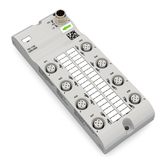
WAGO 765-1706/200-000 Manual (76 pages)
16-Channel Digital Input/Output; IO-Link Class B Hub
Brand:
WAGO
| Category:
Control Unit
| Size: 3 MB
Table of Contents
Table of Contents
3
Provisions
6
Intended Use
6
Typographical Conventions
7
Legal Information
9
Safety
10
General Safety Rules
10
Electrical Safety
10
Thermal Safety
10
Mechanical Safety
10
Indirect Safety
11
Overview
12
Properties
13
View
13
Table 1 Legend for "View" Figure
13
Table 2 Supply Voltage and IO-Link
15
Table 4 Digital Input/Output (2-Channel, 2L Powered)
15
Table 3 Digital Input/Output (2-Channel, 1L Powered)
15
Digital Inputs/Outputs
15
Connections
15
Supply Voltage and IO-Link
15
Circuit Diagram
16
Table 6 Mechanical Data
17
Table 7 Connection Technology
17
Table 8 Digital Input/Output, 1L or 2L Powered
17
Connection Technology
17
Mechanical Data
17
Product
17
Technical Data
17
Power Supply
18
Table 9 Total Load
18
Table 10 Power Supply
18
Electrical Safety
19
Environmental Conditions
19
Table 11 Electrical Safety
19
Table 12 Environmental Requirements
19
Communication
20
Derating
20
Table 13 Communication
20
Table 14 Standards and Regulations
21
Approvals
21
Regulations and Standards
21
Functions
22
Process Image
22
Monitoring Functions
22
Overload Protection
22
Table 15 IO-Link Hub: Input Process Data
22
Table 16 IO-Link Hub: Output Process Data
22
Parameterization Tools
23
WAGO IO-Link Configurator
23
Table 17 Overview of Parameterization Tools for IO-Link Hubs
23
WAGO I/O Field App
24
Planning
25
Structure Guidelines
25
Installation Site and Touch-Proof Protection
25
Power Supply Concept
25
Design Power Supply
25
Table 18 IO-Link Hub 765-1706/100-000 - Currents in Supply Cable 1L
26
Table 19 IO-Link Hub 765-1706/100-000 - Currents in Supply Cable 2L
27
Table 20 IO-Link Hub 765-1706/100-000 - Rules for Supply Cables 1L and 2L
27
Connection Example
28
Input Configuration
29
Table 21 IODD
29
Settings Options
29
Port Configuration
29
Device Description Files (IODD)
29
Configuration of the Substitute Value Behavior for the Digital Outputs
30
Switch on and off Behavior
30
Retentive Data
30
Behavior in the Event of a Communication Interruption
31
Behavior in the Event of a Brief Power Supply Interruption
31
Behavior if Configuration Data Is Lost or Invalid
31
Transport and Storage
32
Before Installation
33
Installation Instructions
33
Installation and Removal
33
Tools Required for Installation
33
Installation
33
Note on Protecting against Heat Generation by the Product
34
Installation Distances
34
Installation
34
Removal
34
Tools Required for Removal
34
After Removal
35
Removal
35
Before Removal
35
Connection
36
Connect Cables
36
Connect Power Supply
36
General Information on Installation
36
Connect Sensors/Actuators
37
Table 22 Connecting Digital Inputs/Outputs
38
IO-Link Object Directories
40
Table 23 IO-Link Object Directory
40
Parameterizing a Module with the WAGO I/O Field App
40
Parameterization
40
Commissioning
40
Index 0 (0X0) - "Direct Parameter Page 1" Object
43
Index 1 (0X01) - "Direct Parameter Page 2" Object
43
Index 2 (0X02) - "System Command" Object
43
Table 24 Index 0 (0X00) - Direct Parameter
43
Table 25 Index 2 (0X02) - "System Command" Object
43
Index 3 (0X03) - "Data Storage Index" Object
44
Table 26 Index 3 (0X03) - "Data Storage Index" Object
44
Table 27 Coding of the Command Code for Data Storage
44
Table 28 Coding of the State_Property (State of Data Storage)
44
Table 31 Structure of the Index Lists
45
Table 30 Meaning of the DS_UPLOAD_FLAG
45
Table 29 Coding of the State of Data Storage
45
Table 32 Index 12 (0X0C) - "Device Access Locks" Object
46
Index 12 (0X0C) - "Device Access Locks" Object
46
Index 13 (0X0D) - "Profile Characteristics" Object
47
Index 32 (0X20) - "Error Count Since Last Start" Object
47
Index 36 (0X24) - "Device Status" Object
47
Table 33 Index 13 (0X0D) - "Module Profile Characteristics" Object
47
Table 34 Index 32 (0X20) - "Error Count Since Last Start" Object
47
Table 35 Index 36 (0X24) - "Device Status" Object
47
Table 36 Possible Values of the Device Status
47
Table 38 Index 64 (0X40) - "Port Configuration" Object
48
Table 39 Configuration of the 16 Digital Inputs or Outputs
48
Index 37 (0X25) - "Detailed Service Status" Object
48
Table 37 Index 37 (0X25) - "Detailed Service Status" Object
48
Table 5 Product
48
Index 64 (0X40) - "Port Configuration" Object
48
Index 65 (0X41) - "DI Filter Configuration" Object
49
Table 40 Index 65 (0X41) - "Digital Input Filter Configuration" Object (DI Filter Configuration)
49
Table 41 Configuration of the Input Filters
49
Table 43 Index 66 (0X42) - "Test Input/Output" (Test IO) Object
50
Index 66 (0X42) - "Test Input/Output" (Test IO) Object
50
Table 42 Index 66 (0X42) - "Test Input/Output" (Test IO) Object - Enabling Test Mode
50
Index 68 (0X44) - "Port Temperature" Object
53
Table 44 Index 67 (0X43) - "Test Event" Object
53
Table 45 Index 67 (0X43) - "Test Event" Object
53
Table 46 Index 68 (0X44) - "Port Temperature" Object
53
Index 67 (0X43) - "Test Event" Object
53
Table 47 Index 69 (0X45) - "Supply Voltage (Pin 1)" Object
54
Table 48 Index 70 (0X46) - "Voltage of the Digital Inputs and Outputs" Object (DIO Voltage)
54
Index 70 (0X46) - "Voltage of the Digital Inputs and Outputs" Object (DIO Voltage)
54
Index 69 (0X45) - "Supply Voltage (Pin 1)" Object
54
Index 71 (0X47) - "Supply Current" Object
56
Table 49 Index 71 (0X47) - "Supply Current" Object
56
Index 72 (0X48) - "Current at the Digital Inputs and Outputs" Object (DIO Current)
57
Table 50 Index 72 (0X48) - "Current at the Digital Inputs and Outputs" Object (DIO Current)
57
Index 73 (0X49) - "Configuration of the Substitute Value Behavior for the Digital Outputs" Object
58
Table 51 Index 73 (0X49) - "Configuration of the Substitute Value Behavior for the Digital Out- Puts" Object
58
Table 52 Configuration of the Behavior of the Digital Outputs in the Event of an Error
59
Table 53 Index 74 (0X4A) - Internal Supply Voltage
60
Table 55 Configuration of the 16 Digital Inputs
61
Table 54 Index 75 (0X4B) - "Digital Inversion Configuration" Object (DI Inversion Configuration)
61
Index 75 (0X4B) - "DI Inversion Configuration" Object
61
Index 76 (0X4C) - "Debug Information" Object
62
Table 56 Index 76 (0X4C) - "Debug Information" Object
62
Diagnostics
63
Diagnostics Via Indicators
63
Table 57 2L Status (Class B)
63
Table 58 2L Status (Firmware Loading Mode)
63
Table 59 Port Status
63
Table 61 IO-Link Events of the Current Monitoring
64
Table 60 IO-Link Device Status
64
Diagnostics Via IO-Link
64
Table 62 IO-Link Events for Monitoring against Undervoltage and Overvoltage
66
Table 63 IO-Link Events of the Overtemperature Monitoring
67
Service
68
Update Firmware
68
Decommissioning
70
Disposal and Recycling
70
Table 64 WEEE Mark
70
Appendix
71
Protected Rights
71
List of Tables
72
List of Figures
74
Advertisement
Advertisement
Related Products
WAGO 7650-654/000-001
WAGO 765-4103/100-000
WAGO 767-4803/000-800
WAGO 761-214
WAGO 767-1201
WAGO 767-5401
WAGO 767-4801/000-800
WAGO WAGO-TO-PASS 761
WAGO 761-112
WAGO 761-110
WAGO Categories
I/O Systems
Control Unit
Power Supply
Switch
Controller
More WAGO Manuals
Login
Sign In
OR
Sign in with Facebook
Sign in with Google
Upload manual
Upload from disk
Upload from URL