
Related Manuals for WAGO 765-4103/100-000


Summary of Contents for WAGO 765-4103/100-000
- Page 1 WAGO I/O System Field 4-Port IO-Link Master Class A; PROFINET; 24 V DC; 2.0 A; 4 × M12 Connection 765-4103/100-000 Product manual | Version 2.2.0...
- Page 2 We wish to point out that the software and hardware terms as well as the trademarks of companies used and/or mentioned in the present manual are generally protected by trademark or patent. WAGO is a registered trademark of WAGO Verwaltungsgesellschaft mbH. Product manual | Version: 2.2.0 4PORT IOL-A FLD PN DC 24V 2.0A...
-
Page 3: Table Of Contents
Process Image ...................... 26 Forcing ........................ 27 Monitoring Functions ..................... 28 Overload protection .................... 29 Parameterization Tools .................. 29 Overview ...................... 29 5.5.1 WAGO IO-Link Configurator................. 30 5.5.2 Product manual | Version: 2.2.0 4PORT IOL-A FLD PN DC 24V 2.0A... - Page 4 Table of Contents 765-4103/100-000 WAGO Webserver I/O Field ................. 31 5.5.3 WAGO I/O Field app .................. 32 5.5.4 Communication Interfaces.................. 33 PROFINET .................... 33 5.6.1 OPC UA Server .................... 34 5.6.2 Planning .......................... 35 Structure Guidelines.................... 35 Data Security .................... 35 6.1.1...
- Page 5 Forcing for IO-Link Ports............ 95 WAGO IO-Link Configurator................. 97 10.3.2 WAGO I/O Field app .................. 97 10.3.3 10.3.3.1 Parameterizing a Module with the WAGO I/O Field App ..... 97 OPC UA Server .................... 97 10.3.4 10.3.4.1 Parameterizing the Product via OPC UA.......... 98 10.3.4.1.1 Identifying Devices..............
- Page 6 Table of Contents 765-4103/100-000 Service .......................... 128 12.1 Resetting to Factory Settings ................ 128 12.2 Updating Firmware .................... 128 Decommissioning ...................... 129 13.1 Disposal and Recycling .................. 129 Appendix........................ 130 14.1 Record Data Sets .................... 130 IOL_CALL / IO_LINK_DEVICE (Record 0xB400) ........ 130 14.1.1...
-
Page 7: Provisions
The terms set forth in the General Business and Contract Conditions for Delivery and Service of WAGO GmbH & Co. KG and the terms for software products and products with integrated software stated in the WAGO Software License Contract – both available at ü www.wago.com... -
Page 8: Typographical Conventions
Provisions 765-4103/100-000 Individual agreements always have priority. Obligations of Installers/Operators The installers and operators bear responsibility for the safety of an installation or a sys- tem assembled with the products. The installer/operator is responsible for proper installa- tion and safety of the system. All laws, standards, guidelines, local regulations and ac- cepted technology standards and practices applicable at the time of installation, and the instructions in the the products’... - Page 9 765-4103/100-000 Provisions Figures Figures in this documentation are for better understanding and may differ from the actual product design. Notes DANGER Type and source of hazard Possible consequences of hazard that also include death or irreversible injury • Action step to reduce risk...
- Page 10 Provisions 765-4103/100-000 without any reference to patent rights. WAGO GmbH & Co. KG, or for third-party prod- ucts, their manufacturer, retain all rights regarding patent, utility model or design registra- tion. ® Third-party trademarks are referred to in the product documentation. The “...
-
Page 11: Safety
765-4103/100-000 Safety Safety 2.1 General Safety Rules • This documentation is part of the product. Therefore, retain the documentation during the entire service life of the product. Pass on the documentation to any subsequent user of the product. In addition, ensure that any supplement to this documentation is included, if necessary. -
Page 12: Indirect Safety
In addition, note the information on the product housing and further infor- mation, e.g. at ü www.wago.com/<item number>. • Only permit skilled personnel approved by WAGO to perform repair work. Product manual | Version: 2.2.0 4PORT IOL-A FLD PN DC 24V 2.0A... -
Page 13: Overview
Overview Overview The module is part of the WAGO I/O System Field 765. It is intended for industrial use within a PROFINET network and communicates with a central controller and/or directly with the control level if applicable. Several sensors can be connected to the product for connection to the field level. -
Page 14: Properties
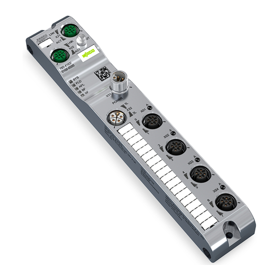
Properties 765-4103/100-000 Properties 4.1 View Figure 1: View Table 1: Legend for “View” Figure Function Position Custom Name Description ETHERNET ETHERNET interface, M12, D-coded, PROFINET port 1 Product manual | Version: 2.2.0 4PORT IOL-A FLD PN DC 24V 2.0A... -
Page 15: Connections
765-4103/100-000 Properties Function Position Custom Name Description LNK (X21) Link LED for port X21 ACT (X21) Activity LED for port X21 ETHERNET interface, M12, D-coded, PROFINET port 2 LNK (X22) Link LED for port X22 ACT (X22) Activity LED for port X22 ®... -
Page 16: Communication Interfaces
Properties 765-4103/100-000 Supply Voltage In- Supply Voltage Signal Description Output M12, L-coded, plug, M12, L-coded, 5-pin (4 + FE) socket, 5-pin (4 + Note Upper limit on current consumption from X32 (Power out) Before connecting one or more products to the power supply on socket X32 (Power out), 8 Power Supply Examples... -
Page 17: Technical Data
765-4103/100-000 Properties Figure 2: Circuit Diagram for Each Port 4.4 Technical data 4.4.1 Product Table 5: Product Property Value Item Number 765-4103/100-000 Product function 4-Port-IO-Link Master Class A Product name (short) 4 PORT IOL-A FLD PN 24 VDC 2.0 A Product name (long) 4-Port IO-Link Master Class A;... -
Page 18: Table 8 Io-Link Port (Class A)
Properties 765-4103/100-000 Property Value PROFINET connection 2 × M12, D-coded, socket, 4-pin IO-Link ports 4 × M12, A-coded, socket, 5-pin Tightening torque M12: 1.0 Nm IO-Link Port (Class A) Table 8: IO-Link Port (Class A) Property Value Value (per UL) IO-Link Master (Class A) Specification V1.1... -
Page 19: Table 9 Total Load
765-4103/100-000 Properties Property Value Value (per UL) Output current, L1 with IO-Link operating mode Maximum 1.0 A with conductor size AWG 22/0.34 mm and cable length of up to 20 m (per IO-Link specifica- tion) Maximum 4.0 A with increased conductor cross-sec- tion or reduced cable length (max. voltage drop of 1.2 V for both feed and return line individually) -
Page 20: Power Supply
Properties 765-4103/100-000 4.4.4 Power Supply Table 10: Power Supply Parameters Value Value (per UL) Supply voltage, 1L, 2L 24 VDC, –25 %/+30 % 24 VDC, –25 %/+20 % (18 VDC ... 31.2 VDC) (18 VDC ... 28.8 VDC) Voltages above 34 V can permanently damage the de- vice. Voltages below approx. 11 V lead to device reset. -
Page 21: Electrical Safety
765-4103/100-000 Properties 4.4.5 Electrical Safety Table 11: Electrical Safety Property Value Insulation resistance 60 VDC Test voltage 550 VAC RMS Min. creepage distance 0.7 mm Requirements • Use of PELV/SELV power supplies • When SELV power supplies are used: SELV power supplies with supply via the same network phase •... -
Page 22: Table 15 Opc Ua Server
Properties 765-4103/100-000 Property Value Output data IO-Link: 12 ... 144 bytes Operation with 4 IO-Link 32 I / 32 O + PQI: 144 bytes (= 130 bytes of process data + 5 bytes of IOPS + 9 bytes of IOCS) Operation with 8 DIs: 12 bytes (= 2 bytes of process data + 1 bytes of IOPS + 9 byte of IOCS) -
Page 23: Derating
The product provides measured values for temperature and current, which you can display with WAGO Webserver I/O Field or read out via OPC UA. The following figure shows the maximum permissible current (I) that can flow into the product as a function of the surrounding air temperature (T). -
Page 24: Regulations And Standards
Properties 765-4103/100-000 Figure 5: Derating of a Contact (Pin) of the A-Coded Connections Port X01, X02, ... (for Core Cross-Section = 0.34 mm /AWG 22) High currents may occur on connections port X01, X02, ... on pin 1 and pin 3. 4.6 Regulations and Standards The following regulations and standards were used in the development of the module: Table 17: Standards and Regulations... -
Page 25: Approvals
765-4103/100-000 Properties 4.7 Approvals The following approvals have been granted for the product: Conformity marking UL 61010-1 and UL In preparation. 61010-2-201, “Ordinary Location” ® Bluetooth This module has an RF transmitter with the follow- ing specifications: • Operating frequency: 2402–2480 MHz... -
Page 26: Functions
Functions 765-4103/100-000 Functions 5.1 Process Image IO-Link Master Submodule Process Data The process data of the digital inputs and outputs can be transferred on a port basis (the default) or pin basis. The following tables show the port and pin assignment. -
Page 27: Forcing
765-4103/100-000 Functions PQI (Port Qualifier Information) The PQI (Port Qualifier Information) provides status information for the IO-Link port IO- Link device. Table 22: Port Qualifier Information Flag Description Reserved, 0 Reserved, 0 NewPar New parameters 0: No IO-Link device product parameter update detected 1: IO-Link device product parameter update detected: IO-Link master performs a “data storage upload,”... -
Page 28: Monitoring Functions
The “Forcing” function can be accessed through the following tools: • WAGO I/O Field Webserver • WAGO I/O Field app on mobile devices Systems like SPS, TIA Portal and the like also have forcing functions. Such forcing func- tions should not be confused with the ones described in this section and will not be con- sidered within the context of this section. -
Page 29: Overload Protection
The measurements are performed for the module and for pin 1, pin 2 and pin 4 of each port. The measured values can be displayed in the WAGO I/O Field Webserver or the WAGO I/O Field app. Alternatively, an OPC UA client can read out the measured values and display them. -
Page 30: Wago Io-Link Configurator
OPC UA client are overwritten. Parameters via PROFINET take precedence. If you have changed parameters of the port configuration via the WAGO I/O Field Web- server, the WAGO I/O Field app, the WAGO IO-Link Configurator or the OPC UA Client, please note that these changes are initially applied by the module, but the I/O controller overwrites the port configuration again at the next start-up. -
Page 31: Wago Webserver I/O Field
IODD (device description files for IO-Link modules) is more flexible. For example, you can access the IODD server directly to import IODDs. The WAGO IO-Link Configurator software can be launched from the Start menu or desk- top icon, either as an independent program or in connection with WAGO-I/O-CHECK. It then provides the necessary functions for connecting to or searching for WAGO IO-Link masters. -
Page 32: Wago I/O Field App
Sign out 5.5.4 WAGO I/O Field app The WAGO I/O Field app is an app for maintenance, diagnostics, operation and monitor- ing of installed WAGO I/O System Field modules and IO-Link devices. This app allows you to display product information, read and write process data and ad- just settings and parameters for both fieldbus modules and IO-Link devices. -
Page 33: Communication Interfaces
You can find Product-specific information on the WAGO App I/O Field in the online help for the app. An iOS version of the WAGO I/O Field app is available for free in the Apple App Store, and an Android version in the Google Play Store. -
Page 34: Opc Ua Server
Functions 765-4103/100-000 5.6.2 OPC UA Server The module has an integrated OPC UA server. Function Overview • Read module identification • Read configuration • Read measured values: current, voltage, temperature • Events: overcurrent, overload and overtemperature • Read status information •... -
Page 35: Planning
• Do not connect control components and control networks to an open network such as the Internet or an office network. WAGO recommends putting control components and control networks behind a fire- wall. • In the control components, close all ports and services not required by your application to minimize the risk of cyber attacks and to enhance cybersecurity. -
Page 36: Power Supply Concept
Greater shielding performance is achieved via low-impedance connection between shielding and ground. For this purpose, connect the shielding over a large surface area, e.g., using the WAGO 790 Shield Connection System. This is especially recom- mended for large-scale systems where equalizing or high impulse currents may occur. - Page 37 765-4103/100-000 Planning Consumption For each supply cable, it is necessary to take into account the consumption that depends on the connected devices. Supply Cable 1: • Logic supply (about 200 mA) • Power supply of all connected sensors/actuators via 1L • Power supply of successive devices via 1L Supply Cable 2: •...
-
Page 38: Table 27 Upper Limits For Current On The Individual Pins Of The Connections
Planning 765-4103/100-000 An upper limit of 16 A applies to the total current in a supply cable. If this upper limit is ex- ceeded, there is a risk of destruction of or damage to the module. To avoid this, protect each supply line with a fuse or circuit breaker. In connection with this, also read section 8 Requirements on the Power Supply... -
Page 39: Table 28 Module 765-4103/100-000 - Currents In Supply Cable 1
Note that the sum of the currents of pins 1, 2 and 4 flows to pin 3. Product-Specific Information For supply cable 1 of the 765-4103/100-000 IO-Link Module, the currents declared in the following table must be taken into account: Table 28: Module 765-4103/100-000 –... -
Page 40: Requirements On The Power Supply
Planning 765-4103/100-000 Current Supply Cable 1 Supply Line 2 Ports Ports X01, ... , X04 (henceforth summarized as port X0i for 1 ≤ i ≤ 4) Supply current on pin 1 (rule 3) ≤ 4 A X0i_pin1_1L Signal current on pin 2/4 in normal ≤... -
Page 41: Power Supply Examples
These examples assume that the IO-Link inputs/outputs are configured as digital outputs. Example of Individual Power Supply This example considers a single 765-4103/100-000 module where no additional devices are powered through its PWR OUT connection (X32). Product manual | Version: 2.2.0... - Page 42 Example of a Power Supply Group with an IO-Link Hub Connection Example 1 In what follows, we consider a power supply group consisting of a 765-4103/100-000 IO- Link Master and a 765-1701/200-000 IO-Link Hub. The two products are connected via IO-Link.
- Page 43 Since the 765-1701/200-000 IO-Link Hub gets its operating voltage from the 765-4103/100-000 IO-Link master, port X01 (pin 1) of the module has a load of 3.2 A = 1 A + 1 A + 0.5 A + 0.5 A + 0.2 A, which is below the maximum load capacity of 4 A and thus permissible.
- Page 44 Figure 8: Power Supply Group with 765-4103/100-000 – Connection Example 2 To do so, we consider port X01 of the 765-4103/100-000 module: This has a load of 5.2 A = 2 A + 2 A + 0.5 A + 0.5 A + 0.2 A on pin 1. That exceeds the maximum load capacity of 4 A and is thus not permissible.
-
Page 45: Settings Options
WAGO I/O Field app. ® 1: activation The Bluetooth interface cannot be enabled by an optical denied signal of a mobile device and in connection with the WAGO I/O Field app. -
Page 46: Table 32 Parameters Of The "Io-Link Xx I / Xx O + Pqi" Submodule
Planning 765-4103/100-000 Table 32: Parameters of the “IO-Link XX I / XX O + PQI” Submodule Parameter Parameters Default Value Description Group Range Digital con- DI logic I/Q 0: DI not in- Pin 2 is a digital input. The input signal is not inverted. -
Page 47: Table 33 "Port Cycle Time
765-4103/100-000 Planning Parameter Parameters Default Value Description Group Range 1: type- A product check for the indicated device type is per- compatible formed for validation or backup of connected IO-Link device slave products (V1.0) 2: type- compatible device (V1.1) 3: type- compatible V1.1 device... -
Page 48: Table 34 "Di" (Digital Input) Parameters
Planning 765-4103/100-000 Value Range Time Basis Factor Port Cycle Time Example (Bits 6+7) (Bits 0 ... 5) (Formula) 100: 20.8 ms 128 ... 191 1.6 ms (10) 0 ... 63 32 ms + 1.6 ms × 133: 40.0 ms factor 158: 80.0 ms 183: 120.0 ms 192 ... 255 Reserved (11) 0 ... 63 This value range is reserved. -
Page 49: Table 35 "Do" (Digital Output) Parameters
765-4103/100-000 Planning Parameter Parameters Default Value Description Group Range Digital port Enable port 0: disable The PROFINET port diagnostics are disabled, i.e. no di- parameters diagnostics agnostic alarms are triggered. 1: enable PROFINET port diagnostics are enabled. Configura- 0: PDCT Configuration is performed via a “port and device config-... -
Page 50: Table 36 Parameters Of The "Deactivated" Submodule
Planning 765-4103/100-000 Parameter Parameters Default Value Description Group Range DO IQ sub- DO substi- 0: set low Set digital output pin 2 to low level in the event of error. stitute con- tute configu- 1: set high Set digital output pin 2 to high level in the event of error. -
Page 51: Setting The Profinet Configuration
765-4103/100-000 Planning Parameter Parameters Default Value Description Group Range DO IQ sub- DO substi- 0: set low Default setting for disabled port. stitute con- tute configu- figuration ration (only for Class A) Digital port Enable port 0: disable Default setting for disabled port. - Page 52 Planning 765-4103/100-000 Submodule Description Input Output Process Data (PD_IN) Process Data (PD_OUT) Digital Output Digital Output 1 byte IO-Link 32 I / 32 O + PQI IO-Link with 32 bytes of in- 32 bytes + 1 byte of PQI 32 bytes put data and 32 bytes of...
-
Page 53: Transport And Storage
765-4103/100-000 Transport and Storage Transport and Storage The original packaging offers optimal protection during transport and storage. • Store the product in suitable packaging, preferably the original packaging. • Only transport the product in suitable containers/packaging. • Make sure the product contacts are not contaminated or damaged during packing or unpacking. -
Page 54: Installation And Removal
Installation and Removal 765-4103/100-000 Installation and Removal 8.1 Installation 8.1.1 Tools Required for Installation The following tools are required for installation: • Allen wrench for the M4 hex head mounting screws The following additional items are only required for installation where no threaded hole is present: •... -
Page 55: Note On Protecting Against Heat Generation By The Product
765-4103/100-000 Installation and Removal • When mounting, be sure not to contaminate the connections. The contamination dam- ages the contacts, which can limit the reliability of the contacts. 8.1.4 Note on Protecting against Heat Generation by the Product During operation, the product can get hot! Therefore, always note the following informa- tion: •... -
Page 56: Grounding
Installation and Removal 765-4103/100-000 8.1.8 Grounding Functional Ground The L-coded M12 pluggable connectors of the product’s power supply have one FE (functional ground) pin, which is connected to the metal housing of the product. The metal housing in turn has a central grounding point for functional ground. You can ground the module as follows: •... -
Page 57: Connection
765-4103/100-000 Connection Connection 9.1 General Information on Installation When laying cables, the local conditions and the applicable regulations are crucial for im- plementation. Be sure to maintain the minimum clearances between the cabling and possible sources of interference (including machines, welding equipment and power lines) to prevent loss and corruption of data. -
Page 58: Connect Power Supply
Note that the connection for the additional supply voltage is not monitored for overload. If the maximum current carrying capacity is exceeded, this can damage the pluggable con- nectors. WAGO recommends using pre-assembled cables. The following figure gives an example of feeding in and passing on the supply voltages: Product manual | Version: 2.2.0... - Page 59 765-4103/100-000 Connection Figure 9: Example of Feeding in and Passing on the Supply Voltages In connection with this figure, note that the cables illustrated for current paths 1L and 2L are realized not as separate cables, but rather as separate wires within one common ca- ble.
-
Page 60: Connecting Cables
Cable cross-section 9.3 Connecting Cables WAGO recommends using 765 Series connecting cables, pluggable connectors and ac- cessories for 756 Series products, which have been tailored specifically to the WAGO I/O System Field. 8 Connecting Cables [} 60] The tightening torques given in section apply to the plug- gable connectors of the connecting cables. - Page 61 3. Tighten the pluggable connector using the knurled-head screw. Connecting Multiple Products to One ETHERNET Network The fieldbus module of the WAGO I/O System Field has two connections with an inte- grated switch to allow wiring of a line topology.
-
Page 62: Connect Sensors/Actuators
Connection 765-4103/100-000 Figure 11: Network Topology (Module Appearance May Differ) 9.5 Connect Sensors/Actuators The sensor/actuator cable powers the connected sensors/actuators and transfers the sensor and actuator signals. Note the current load capacity of the supply contacts; see “Rule 3,” section Rule 3: Ports X01, X02 etc. - Page 63 765-4103/100-000 Connection Ethernet Ethernet PWR OUT PWR IN DIO B DIO B DIO B DIO B Figure 12: Schematic Circuit Diagram of the Power Supply The following table shows the connection options for IO-Link devices (class A) and digital inputs and outputs.
-
Page 64: Table 39 Connecting An Io-Link Device Or Digital Input Or Output
Connection 765-4103/100-000 Table 39: Connecting an IO-Link Device or Digital Input or Output Connection Option Description Connection of an IO-Link device Required port configuration: IO-Link master and pin 2 disabled. Connection of an IO-Link device and a digital input on channel B. - Page 65 765-4103/100-000 Connection Connection Option Description Connection of a digital output on channel A and a digital input on channel B. Required port configuration: pin 4 as a digital output and pin 2 as a digital in- put. Product manual | Version: 2.2.0...
-
Page 66: Commissioning
Commissioning 765-4103/100-000 Commissioning Note The figures and descriptions below are an example configuration The figures and descriptions this section contains are based on an example configura- tion. Your configuration, and thus the content shown, may differ from the content illustrated here. - Page 67 765-4103/100-000 Commissioning Figure 13: List of the Products Found on the Local Network • Identify the device, e.g., on the basis of the MAC address or the product type IO System Field-765-xxxx. • Use the mouse cursor to select the corresponding device from the list of devices found.
-
Page 68: Configuration
Commissioning 765-4103/100-000 • Click OK. The module is now accessible via the IP address, and you can open WAGO Web- server I/O Field with a browser, for example. 10.2 Configuration 10.2.1 Parameterizing the Module via PROFINET ü To configure the PROFINET IO-Controllers, you need the GSDML file. -
Page 69: Parameterization
10.3.1 WAGO Webserver I/O Field 10.3.1.1 Call WAGO Webserver I/O Field This section describes how you can use the integrated software WAGO I/O Field Web- server to get access to detailed information on the current operating state of the product and make settings to affect the product’s behavior. -
Page 70: Maintenance Information
Commissioning 765-4103/100-000 When the user interface of the WAGO I/O Field Webserver opens, the main page of the Dashboard appears first. It shows the following product information: Table 40: Data on the “Dashboard” Page Section Information Displayed Device information Product data and WAGO contact information... -
Page 71: Displaying Measured Values And Information On Connected Io-Link Devices
765-4103/100-000 Commissioning ð You can now access information about the desired port. For each port, you can select from the following five tabs: Table 41: Tabs for Port Information and Settings (IO-Link Ports X01, X02 etc.) Description Information Displays the current measured values for temperature, voltage and cur- rent, as well as the port state, individually for each of pin 1, pin 2 and pin 4. -
Page 72: Table 42 Additional Information On The Products Connected To The Selected Port
Commissioning 765-4103/100-000 States of the Connection Pin The possible states of the connection pin are: • OK • Short circuit • Module-internal overload protection has triggered • Module-internal overtemperature protection has triggered • Module-internal overvoltage protection has triggered • Overcurrent •... -
Page 73: Displaying Port Status Information
765-4103/100-000 Commissioning Information Description Vendor name Detailed name of the manufacturer/vendor of the connected device (up to 64 characters) Vendor text Additional text for description of the manufacturer/vendor (up to 64 char- acters) Product name Complete name of the connected product (up to 64 characters) -
Page 74: State
Commissioning 765-4103/100-000 1. From the main menu of the Webserver (left), select the menu item which you want to view information about. 2. Open the Status tab. ð The Status tab opens. The current port status information appears. 10.3.1.3.4 State This shows the current port status information of the IO-Link port. -
Page 75: Quality
765-4103/100-000 Commissioning 10.3.1.3.5 Quality This shows the Port Quality Info, including information on the validity of the process data for input and output (separately). The content is binary coded. Table 44: Meaning of the Individual Bits Bits of Port Quality Info... -
Page 76: Device Id
Commissioning 765-4103/100-000 10.3.1.3.12 Device ID This value is the device ID of the connected product. 10.3.1.3.13 Displaying Process Data You can view the process data associated with a specific port on the Process Data tab. Proceed as follows to view the process data for a port: 1. -
Page 77: Parameterizing The Module Via The Wago I/O Field Webserver
765-4103/100-000 Commissioning 10.3.1.4 Parameterizing the Module via the WAGO I/O Field Webserver You can make the following settings on the module with WAGO Webserver I/O Field: 8 Accessing a Connected IO-Link Device [} 77] • 8 Configure Ports [} 80] • 8 Configuring IP Parameters [} 84] •... - Page 78 Commissioning 765-4103/100-000 Read Access Figure 20: Ports X0i – Read Access to IO-Link Device (Example View) To read data from the connected IO-Link device, proceed as follows: 1. On the IOL tab, enter the index of the connected IO-Link device you want to access into the Index field as a hexadecimal value.
- Page 79 765-4103/100-000 Commissioning Figure 21: Ports X0i – Read Access to IO-Link at Index 43 and Subindex 0 Unsuccessful (Read Failed, Example View) If the operation was not successful, an error message appears in the history with error codes from the IO-Link master and IO-Link device.
-
Page 80: Configure Ports
Commissioning 765-4103/100-000 If the operation was successful, the text Write ok: and the result appear in the history. The entries in the history then have the following structure: Time – Index:Subindex – Write ok: <Result> If the operation was not successful, an error message appears in the history with error codes from the IO-Link master and IO-Link device. -
Page 81: Table 47 "Port Mode" Drop-Down Menu: Selecting The Operating Mode For Pin 4 Of The Selected Io-Link Port
765-4103/100-000 Commissioning Name Type Description IQ behavior (pin 2) Drop-down menu IQ behavior of the port (configuration of pin 2) Validation and backup Drop-down menu Validation and Backup Settings for Device Check When Replacing Devices PortCycleTime Input field Expected cycle time of the port... -
Page 82: Table 48 Iq Behavior Drop-Down Menu - Configuration Of Pin 2 (I/Q) For Io-Link Class A De- Vices
Commissioning 765-4103/100-000 Selection Option Description Digital Output The port is used as a digital output. All elements of the port configuration are ig- nored except for the input and output data length. Digital output, static on The port is used as a digital output. The signal on pin 4 is permanently set to logic 1 (for testing purposes only). -
Page 83: Table 50 Possible Values Of The Backup Level Parameter
765-4103/100-000 Commissioning Inspection Level Description TYPE_COMP A device check for type compatibility is performed. For the device check, the actual vendor ID is compared to the vendor ID setting in the configuration, and the actual device ID is compared to the device ID setting in the configuration. -
Page 84: Configuring Ip Parameters
Commissioning 765-4103/100-000 DeviceID Input Field This element contains the expected device ID (DeviceID, 3 bytes) of the connected de- vice. The permissible values range from 1 to 0xFFFFFF. This information is required for the device check for type compatibility. It can be omitted if [No device check] is selected. -
Page 85: Storing Maintenance Information
765-4103/100-000 Commissioning 10.3.1.4.4 Storing Maintenance Information On the Maintenance Information tab, you can store maintenance information, such as the device name, the installation location and date, contact information, a description text or the date of the last and next product service. -
Page 86: Updating Firmware
4. Click the [Apply] button. ð Your changes take effect. 10.3.1.4.5 Updating Firmware With the Firmware upgrade tab, WAGO Webserver I/O Field provides an option for up- dating the product firmware. Figure 25: Settings Menu Item, Firmware Upgrade Tab (Example View) Product manual | Version: 2.2.0... -
Page 87: Resetsetting The Module To The Factory Settings
To update the firmware, you need a firmware container file: FWUPDATE.ZIP. You can get it from the Downloads section of the WAGO website: ü http://www.wago.com. Proceed as follows to update the firmware: 1. In the left-hand column of the WAGO I/O Field Webserver, click the Settings menu item. ð The Device configuration tab appears. -
Page 88: Configure Bluetooth
Reset All All Settings To reset the module to the factory settings, proceed as follows: 1. In the left-hand column of the WAGO I/O Field Webserver, click the Settings menu item. ð The Device configuration tab appears. 2. Select the Factory reset tab. - Page 89 • Switching the Bluetooth wireless connection on/off ® • Switching the Bluetooth LED on/off ® Proceed as follows to access these Bluetooth functions on the WAGO I/O Field Web- server: ® • Open the Bluetooth tab. ® ð The Bluetooth tab appears.
-
Page 90: Table 55 Status Of The Last Bluetooth Firmware Update
® To enable the Bluetooth interface, you must have the WAGO I/O Field app installed on the smartphone or tablet. Proceed as follows: ® • A DM code appears in the “Information” section of the Bluetooth tab. -
Page 91: Logging Users On And Off And Managing Them
765-4103/100-000 Commissioning ® Switching the Bluetooth Interface Wireless Transmitter on/off ® To switch the Bluetooth interface wireless transmitter on: • Slide the Bluetooth Radio switch to the right. ð The Bluetooth ® interface wireless transmitter switches on. ® To switch the Bluetooth interface wireless transmitter off, slide the Bluetooth Radio switch to the left. - Page 92 From the Webserver main menu (left), select the Sign out menu item. ð You can now no longer work in the WAGO I/O Field Webserver with the rights you had been using till this point. The username used to log on is no longer shown in the upper left-hand corner.
- Page 93 765-4103/100-000 Commissioning Figure 29: User Administration Menu Item (Initial State) (Example View) The user root with pre-set password password exists by default; see first row. An additional user can be created in the second row. Proceed as follows: 1. In the Username field, enter the username to use for the user. Users that are al- ready in use are not allowed here.
-
Page 94: Forcing Digital Inputs And Outputs
Commissioning 765-4103/100-000 ð The new user is created and assigned the selected role. Removing Users To remove an existing user from the product’s user administration, proceed as follows: • Click the red square with the white “x” to the right of the user you want to remove. -
Page 95: Forcing For Io-Link Ports
As long as one user is accessing the forcing functionality through a forcing medium, e.g., the WAGO I/O Field Webserver, it is locked for all other users of the module. They cannot access the forcing functionality until the user that is active now terminates his or her ac- cess. - Page 96 As long as one user is accessing the forcing functionality through a forcing medium, e.g., the WAGO I/O Field Webserver, it is locked for all other users of the module. They cannot access the forcing functionality until the user that is active now terminates his or her ac- cess.
-
Page 97: Wago Io-Link Configurator
10.3.3.1 Parameterizing a Module with the WAGO I/O Field App Note Read the online help! You can find Product-specific information on the WAGO App I/O Field in the online help for the app. 10.3.4 OPC UA Server The device has an OPC UA server. An OPC UA client can establish a connection with the device and access the following parameters, among others: •... -
Page 98: Parameterizing The Product Via Opc Ua
Commissioning 765-4103/100-000 Figure 33: OPC UA: Device Information Model 10.3.4.1 Parameterizing the Product via OPC UA 10.3.4.1.1 Identifying Devices The device provides nodes for device identification. For example, the OPC UA client can read out the version of the device firmware used in the SoftwareRevision node. The path to this node is: Root >... -
Page 99: Setting Device Parameters
765-4103/100-000 Commissioning 10.3.4.1.2 Setting Device Parameters The OPC UA server provides nodes with configuration parameters for the device. For ex- ample, the OPC UA client can read out the upper limiting value for temperature in the OverTemperature node. The path to this node is: Root >... -
Page 100: Reading Port Process Values
Commissioning 765-4103/100-000 Table 59: Port-Specific Configuration Parameters Node Name Node Class Access Default Description OverCurrentPin1 Variable Read Warning level for current upper limit on pin 1; unit: 1 mA 0: monitoring not enabled OverCurrentPin2 Variable Read Warning level for current upper limit on pin 2;... -
Page 101: Reading Measured Power Values
765-4103/100-000 Commissioning Note OPC UA client can only read process output data The process output data is written by the PROFINET IO-Controller. The OPC UA client can only read process output data. The following table lists port-specific process data of the digital inputs and outputs. -
Page 102: Reading Out Diagnostic Information
Commissioning 765-4103/100-000 Root > Object > DeviceSet > [device name] > IOLinkMaster > Diag- nostics > Voltage The following table lists device-specific (calculated) measured voltage values. Table 64: Device-Specific (Calculated) Measured Voltage Values Node Name Node Class Access Description MeanVoltage1L Variable Read Average voltage in supply cable 1;... -
Page 103: Table 66 Port Specific Statistical Information
765-4103/100-000 Commissioning Table 66: Port Specific Statistical Information Measurement Node Name Node Class Access Description Current MaxCurrentPin1 Variable Read Maximum current on pin 1 since the value was reset; unit: mA MaxCurrentPin2 Variable Read Maximum current on pin 2 since the value was reset; unit: mA... -
Page 104: Ntp Client Configuration
Commissioning 765-4103/100-000 Measurement Node Name Node Class Access Description MinVoltagePin4 Variable Read Minimum voltage on pin 4 since the value was reset; unit: mV 10.3.4.1.8 NTP Client Configuration The OPC UA server provides nodes for the configuration of the NTP client. The path to this node is: Root >... -
Page 105: Using Opc Ua Client
765-4103/100-000 Commissioning • InputSimulationPin2 • InputSimulationPin4 • OutputPin2 • OutputPin4 • IoLinkInputSimulation • IoLinkOutput Each of these methods has a Force ID parameter. The module monitors the Force function with a watchdog timer. If the OPC UA client be- comes inactive, or the connection via OPC UA is lost, the watchdog timer expires, and the product switches the Force function off. - Page 106 Commissioning 765-4103/100-000 Figure 34: Add Server Dialog – Discovery Tab (Default) Product manual | Version: 2.2.0 4PORT IOL-A FLD PN DC 24V 2.0A...
- Page 107 765-4103/100-000 Commissioning Figure 35: Add Server Dialog – Advanced Tab 4. In the Configuration Name field, enter a name for your configuration, e.g. “Test.” 5. Select the Advanced tab. 6. In the Server Information section of the Advanced tab, enter the following informa- tion in the Endpoint URL field: opc.tcp://<IP address>:4840.
- Page 108 Commissioning 765-4103/100-000 9. Click OK. ð In the project window, UaExpert enters the server under Project > Servers e.g., “Test.” 10. Open the context menu of the server (“Test”) and select Connect. ð The connection is established. 10.3.4.1.10.2 Setting the Module Time via OPC UA Requirements •...
- Page 109 765-4103/100-000 Commissioning Figure 36: NtpClientUpdateConfiguration Node 2. In the context menu, select Call. Figure 37: NtpClientUpdateConfiguration Node – Context Menu ð The Call NtpClientUpdateConfiguration on NtpClient dialog appears. Product manual | Version: 2.2.0 4PORT IOL-A FLD PN DC 24V 2.0A...
- Page 110 Commissioning 765-4103/100-000 Figure 38: NTP Client Configuration Dialog 3. In the Input Arguments section, enter the value 3224725356 for the IP address of the NTP server in the ServerIpAddress field. 4. In the Input Arguments section, enter the number 3224725352 for the IP address of the alternate NTP in the ServerIpAddressFallback field.
- Page 111 765-4103/100-000 Commissioning Figure 39: NTP Client Configuration Dialog (Succeeded) 10.3.4.1.10.3 Enabling Forcing Requirements • You must have an OPC UA client. • You must know the username and password, and this user must have permission to execute methods. • You must have already established a connection to the I/O module.
- Page 112 Commissioning 765-4103/100-000 Figure 40: GetForcingID Method 3. Click [Call]. ð If the method call was successful, then the Force ID is displayed, and “0” appears under Status. The FLD LED on the I/O module flashes at a rate of 1 Hz. Figure 41: GetForcingID Method: Successful ð...
- Page 113 765-4103/100-000 Commissioning Figure 42: GetForcingID Method: Unsuccessful 4. In the OPC UA client, drag the “AssignedForceID” node into the Data Access View window so that the AssignedForceID is read regularly ð Regular reading of the AssignedForceID triggers the watchdog timer and keeps the Force function enabled.
-
Page 114: Table 68 Input Arguments Of The Inputsimulationpin Method
Commissioning 765-4103/100-000 Figure 43: InputSimulationPin4 Method 3. Enter the Force ID, the Force Mask and the Force Data (the input arguments are described below, including an example). 4. Click [Call]. ð If the method call was successful, the input data is transmitted to the controller. -
Page 115: Table 69 Output Arguments Of The Inputsimulationpin Method
765-4103/100-000 Commissioning Input Arguments Description Force Data Input value Bit mask and port assignment: Bit 0: port X01, Bit 1: port X02, Bit 2: port X03, ... Bit value 0: The pin has an input value of 0. Bit value 1: The pin has an input value of 1. -
Page 116: Table 70 Input Arguments Of The Outputpin Method
Commissioning 765-4103/100-000 Figure 44: OutputPin4 Method 4. Click [Call]. ð If the method call was successful, then the output data on the module is forced. ð If the method call was unsuccessful, then “−1” appears under Status. Description of the Input Arguments Table 70: Input Arguments of the OutputPin Method... -
Page 117: Table 71 Output Arguments Of The Outputpin Method
765-4103/100-000 Commissioning Input Arguments Description Example 1 (Force Mask has a value of 4): A value of 0 sets the output value of port X03 to 0. A value of 4 sets the output value of port X03 to 1. -
Page 118: Table 72 Input Arguments Of The Iolinkinputsimulation Method
Commissioning 765-4103/100-000 Figure 45: IoLinkInputSimulation Method 3. Enter the Force ID, check Force Enable, and enter the Force Data (the input argu- ments are described below). 4. Click [Call]. ð If the method call was successful, then the IO-Link input data is transmitted to the controller. - Page 119 765-4103/100-000 Commissioning 10.3.4.1.10.7 Forcing IO-Link Output Data The IoLinkOutput method sets the IO-Link output data of a port. Requirements • You must have an OPC UA client. • You must know the username and password, and this user must have permission to execute methods.
-
Page 120: Table 74 Input Arguments Of The Iolinkoutput Method
Commissioning 765-4103/100-000 Description of the Input Arguments Table 74: Input Arguments of the IoLinkOutput Method Input Arguments Description Force ID Here the OPC UA client must use the Force ID that the OPC UA client had received after the GetForcingID method was called. -
Page 121: Setting The Module Time
765-4103/100-000 Commissioning Figure 47: DisableForcing Method ð If the method call was unsuccessful, then “−1” appears under Status. Description of the Input Arguments Table 76: Input Arguments of the DisableForcing Method Input Arguments Description Force ID Here the OPC UA client must use the Force ID that the OPC UA client had received after the GetForcingID method was called. -
Page 122: Diagnostics
Green Normal operating state Green Flashing (1 Hz) Force mode is active Green Flashing (4 Hz) WAGO IO-Link Configurator is connected to the module Yellow Configuration error Non-operational; no voltage Application Status The APL LED indicates the status of the application. Product manual | Version: 2.2.0... -
Page 123: Table 81 Apl Led
765-4103/100-000 Diagnostics Table 81: APL LED Color State Description Duo LED, red/green/yellow (yellow = simultaneously red and green) LED with no function Yellow Flashing (1 Hz, 5 s) Module has a NameOfStation and/or an IP address. During module startup, the LED flashes for 5 s at 1 Hz. -
Page 124: Table 85 Led States - Ethernet Status
Diagnostics 765-4103/100-000 Table 85: LED States – ETHERNET Status LED State Description Flickering (load-dependent) The indicator switches on and off at a frequency of 10 Hz, indicat- ing high ETHERNET activity: on for 50 ms and then off for 50 ms. -
Page 125: Diagnostics Via Profinet
765-4103/100-000 Diagnostics 11.2 Diagnostics via PROFINET General Alarms Table 88: General Alarms Number Alarm Description Corrective Action (hex) 0x0100 Undervoltage, 1L Undervoltage in supply cable 1L Check supply voltage The supply cable has fallen below the limit- ing value for the minimum voltage... -
Page 126: Table 89 Io-Link Master Diagnostic Alarms
Diagnostics 765-4103/100-000 Table 89: IO-Link Master Diagnostic Alarms Channel Error Extended Chan- Description Corrective Action nel Error Type 0x9502 0x17FF Process data error Check submodule configuration 0x9502 0x1800 No device access / loss of commu- Check IO-Link port nication 0x9502 0x1801... -
Page 127: Table 90 Process Alarms For Io-Link Device Diagnostics
765-4103/100-000 Diagnostics Table 90: Process Alarms for IO-Link Device Diagnostics Channel Error Extended Description of the Error Function Corrective Action on the Con- (PROFINET) Channel Error on the Connected IO-Link Device nected Type IO-Link Device (PROFINET) 0x9500 0x1000 General malfunction IO-Link device reports unknown error... -
Page 128: Service
Service 765-4103/100-000 Service 12.1 Resetting to Factory Settings The device can be reset to the factory settings. Use the WAGO I/O Field Webserver for this purpose. 8 Resetsetting the Module to the Factory You can find information on the procedure in Settings [} 87]. -
Page 129: Decommissioning
765-4103/100-000 Decommissioning Decommissioning 13.1 Disposal and Recycling Table 91: WEEE Mark Logo Description Electrical and electronic equipment may not be disposed of with household waste. This also applies to products without this mark. Electrical and electronic equipment contain materials and substances that can be harmful to the environment and health. -
Page 130: Appendix
Appendix 765-4103/100-000 Appendix 14.1 Record Data Sets PROFINET offers access to device parameters (records) by means of acyclic services. Records can be read from the PROFINET IO device by the PROFINET IO controller with ReadRecord and written to the PROFINET IO device with WriteRecord. -
Page 131: Isdu Read Service
765-4103/100-000 Appendix • Read: During read access, user data is transferred from the IO-Link device to the PROFINET IO controller. The user data is stored temporarily in the user data range of record 0xB400. • Write: During write access, user data is transferred from the PROFINET IO controller to the IO-Link device. -
Page 132: Table 93 Structure Of Iol_Call For An Isdu Read Request (Writerecord Request)
Appendix 765-4103/100-000 Table 93: Structure of IOL_CALL for an ISDU Read Request (WriteRecord Request) Offset Parameter Name Description Type Value Function Fixed value Unsigned8 0x08 Indicates a call header. Port Port number Unsigned8 0x01 … 0x08 FI_Index Fixed value Unsigned16 0xFE4A... -
Page 133: Table 94 Structure Of The Iol_Call (Readrecord Response And In Case Of Success)
765-4103/100-000 Appendix Table 94: Structure of the IOL_CALL (ReadRecord Response and in Case of Success) Offset Parameter Name Description Type Value Function Fixed value Unsigned8 0x08 Indicates a call header. Port Port number Unsigned8 0x01 … 0x08 FI_Index Fixed value Unsigned16... -
Page 134: Isdu Write Service
Appendix 765-4103/100-000 14.1.1.2 ISDU Write Service In order to write data to an IO-Link device via PROFINET record, the following process is required: • The PROFINET IO controller uses WriteRecord and writes the ISDU write request to record 0xB400, indicating the index and subindex This information addresses the port and the object of the IO-Link device that is to be written to, among other things. - Page 135 765-4103/100-000 Appendix Offset Parameter Name Description Type Value IOL_Subindex Object subindex of the IO-Link Unsigned8 [0x00...0xFF] device to be written to. 8 … n IOL_Data User data for write request Record User data to be written to the object of the IO-Link device. At most 232 bytes can be written.
-
Page 136: Error Handling
Appendix 765-4103/100-000 ReadRecord Response: Structure of the IOL_CALL (in Case of Success: Status Octet is 0x00) If the status octet has the value 0, then the ISDU write request has been executed. The response has the following structure: Table 97: Structure of the IOL_CALL (ReadRecord Response and in Case of Success) -
Page 137: Table 100 Port Errors (Error Codes)
765-4103/100-000 Appendix Offset Parameter Contents Data Type Error code IO-Link error codes Unsigned8 Additional Code Additional IO-Link error codes (Additional Code) Unsigned8 Port Errors Table 100: Port Errors (Error Codes) Error code Port Error Description 0x0000 No error No error detected 0x0001 …... - Page 138 Appendix 765-4103/100-000 Error Addi- Event Error Name code tional Description Code 0x80 0x20 Service temporarily SERV_NOTAVAIL unavailable This error type is used if a parameter for a read or write service cannot be accessed due to the current state of the device applica- tion.
-
Page 139: Table 102 "Derived" Errors
765-4103/100-000 Appendix Error Addi- Event Error Name code tional Description Code 0x80 0x41 Inconsistent parame- PAR_SETINCONSIST ter set This error type is used if a block parameter transfer ends with with ParamDownloadEnd or ParamDownloadStore and the plausibility check identifies inconsistencies. -
Page 140: Installation Regulations Specified By Approvals
EU Declaration of Conformity Hereby, WAGO GmbH & Co. KG declares that the radio equipment type 765-4103/100-000 is in compliance with Directive 2014/53/EU. The full text of the EU declaration of conformity is available at the following internet address: ü www.wago.com /765-4103/100-000. -
Page 141: Operational Description
GmbH & Co. KG may void the FCC authorization to operate this equipment. 14.3 Operational Description Product Description The product 765-4103/100-000 is used to capture field signals on sensors, actuators and hubs which have been sent or received by a higher-level controller and output them via IO-Link. -
Page 142: Table 104 Temperature Ranges
Appendix 765-4103/100-000 Maximum antenna gain 1.25 dBi We declare that we meet the EN 62479 standard with respect to the limiting value for low powers less than 20 mW. Therefore, the product fundamentally corresponds to the Euro- pean limiting values for high-frequency radiation. -
Page 143: Protected Rights
765-4103/100-000 Appendix 14.4 Protected Rights ® ® • Adobe and Acrobat are registered trademarks of Adobe Systems Inc. • Android is a trademark of Google LLC. • Apple, the Apple logo, iPhone, iPad and iPod touch are registered trademarks of Apple Inc. - Page 144 Overview of Parameterization Tools .................. Table 25 Parameterization Overview....................Table 26 Function Overview for WAGO I/O Field Webserver and WAGO IO-Link Modules .... Table 27 Upper Limits for Current on the Individual Pins of the Connections ........Table 28 Module 765-4103/100-000 – Currents in Supply Cable 1..........
- Page 145 765-4103/100-000 List of Tables Table 37 PROFINET Modules and Submodules ................Table 38 Port Submodules ....................... Table 39 Connecting an IO-Link Device or Digital Input or Output ........... Table 40 Data on the “Dashboard” Page ..................Table 41 Tabs for Port Information and Settings (IO-Link Ports X01, X02 etc.) .......
- Page 146 List of Tables 765-4103/100-000 Table 73 Output Arguments of the IoLinkInputSimulation Method ........... 118 Table 74 Input Arguments of the IoLinkOutput Method ..............120 Table 75 Output Arguments of the IoLinkOutput Method ..............120 Table 76 Input Arguments of the DisableForcing Method..............121 Table 77 Output Arguments of the DisableForcing Method..............
- Page 147 /AWG 22) ................Figure 6 Connection Example for 765-4103/100-000 Module with Individual Power Supply..Figure 7 Power Supply Group with 765-4103/100-000 – Connection Example 1 ....... Figure 8 Power Supply Group with 765-4103/100-000 – Connection Example 2 ....... Figure 9 Example of Feeding in and Passing on the Supply Voltages ........
- Page 148 List of Figures 765-4103/100-000 Figure 35 Add Server Dialog – Advanced Tab................107 Figure 36 NtpClientUpdateConfiguration Node................109 Figure 37 NtpClientUpdateConfiguration Node – Context Menu ..........109 Figure 38 NTP Client Configuration Dialog ................... 110 Figure 39 NTP Client Configuration Dialog (Succeeded).............. 111 Figure 40 GetForcingID Method....................
- Page 149 765-4103/100-000 List of Figures Product manual | Version: 2.2.0 4PORT IOL-A FLD PN DC 24V 2.0A...
- Page 150 WAGO is a registered trademark of WAGO Verwaltungsgesellschaft mbH. Copyright – WAGO GmbH & Co. KG – All rights reserved. The content and structure of the WAGO websites, catalogs, videos and other WAGO media are subject to copyright. Distri- bution or modification of the contents of these pages and videos is prohibited. Furthermore, the content may neither be copied nor made available to third parties for commercial pur-...
Need help?
Do you have a question about the 765-4103/100-000 and is the answer not in the manual?
Questions and answers