
Related Manuals for GEA VESTA XL H A


Summary of Contents for GEA VESTA XL H A
- Page 1 Operating Instructions ® VESTA Tank Bottom Valve Type H_A/T/F/M Edition 2023-09-26 English...
- Page 2 EU Machinery directive. This document is protected by copyright. All rights reserved. The document may not, in whole or in part, be copied, reproduced, translated or reduced to an electronic medium of machine-readable form without the express permission of GEA Tuchenhagen GmbH. ®...
-
Page 3: Table Of Contents
Table of Contents Table of Contents Notes for the Reader ........................ 6 Binding Character of These Operating Instructions ..............6 Notes on the Illustrations ......................6 Symbols and Highlighting ......................7 Abbreviations and Terms ......................8 Safety ............................10 Safety Note ..........................10 Operator's Duties ........................ - Page 4 Table of Contents Pneumatic Connections ......................28 • Air Requirement ........................28 • Establishing Hose Connections .................... 30 Electrical Connections ......................30 Commissioning ......................... 31 Malfunctions ........................... 32 Maintenance ..........................33 Inspections ..........................33 • Product Contact Seals ......................33 •...
- Page 5 Table of Contents Design of the Joint / Welding Sequence ................... 64 • Information on the Welding Sequence ................. 64 • Execution ..........................64 • Fitting the Welding Device Prior to Welding ................. 65 • Welding Sequence ....................... 65 • Explanation ...........................
-
Page 6: Notes For The Reader
Notes for the Reader Notes on the Illustrations Notes for the Reader The present Operating Instructions are part of the user information for the valve. The Operating Instructions contain all the information you need to transport, install, commission, operate and carry out maintenance for the valve. -
Page 7: Symbols And Highlighting
Notes for the Reader Symbols and Highlighting Symbols and Highlighting In these Operating Instructions, important information is highlighted by symbols or special formatting. The following examples illustrate the most important types of highlighting. DANGER Warning: Fatal Injuries. Failure to observe the warning can cause serious damage to health, or even death. -
Page 8: Abbreviations And Terms
EPDM Material description, short designation according to DIN/ISO 1629: Ethylene Propylene Diene Rubber GEA Group AG group of companies GEA stands for Global Engineering Alliance Material description, short designation according to DIN/ISO 1629: Fluorine rubber Unit of measurement of time [hour]... - Page 9 Notes for the Reader Abbreviations and Terms Abbreviation Explanation Unit of measurement of work [newton metre] 1 Nm = 0.737 lbft NIT OF TORQUE Pound-Force (lb) + Feet (ft) Material description polyamide PTFE Material description polytetrafluorethylene PE-LD Material description low-density polyethylene SET-UP Self-learning installation During commissioning and maintenance, the SET-UP procedure...
-
Page 10: Safety
Safety Operator's Duties Safety Safety Note The valve is operationally reliable. It was built according to state-of-the art standards. Nevertheless, the valve can pose dangers, especially if • the valve is not used in accordance with its intended use, • the valve is not used correctly, •... -
Page 11: Qualification Of Staff
Safety Qualification of Staff The operator's duty of care includes planning the necessary safety meas- ures and monitoring that these measures are observed. The following princi- ples apply: • Only allow qualified staff to work on the valve. • The operator must authorize the staff to carry out the relevant tasks. •... -
Page 12: Supplementary Regulations
Safety Supplementary Regulations Each member of staff must meet the following requirements to be allowed to work on the valve: • Personal qualification for the relevant task. • Sufficient professional qualification for the relevant task. • Instructed with regard to the function of the valve. •... -
Page 13: Instructions For The Safe Operation
Safety Instructions for the Safe Operation Instructions for the Safe Operation Dangerous situations during the operation can be avoided by safety- conscious and proactive behaviour of the staff. General Principles To ensure the safe operation of the valve the following principles apply: •... -
Page 14: Commissioning/Setup Mode
Safety Instructions for the Safe Operation Commissioning/Setup Mode For commissioning, the following principles apply: • Take protective measures against dangerous contact voltages in accord- ance with pertinent regulations. • The valve must be completely assembled and correctly adjusted. All screw connections must be securely tightened. All electrical cables must be installed correctly. -
Page 15: Shutting Down
Safety Instructions for the Safe Operation Shutting Down For shutting down, the following principles apply: • Switch off the compressed air. • Switch off the valve via the main switch. • Padlock the main switch (if fitted) in the off position to prevent it from being switched back on. -
Page 16: Disassembly
Safety Instructions for the Safe Operation Disassembly For disassembly, the following principles apply: • Only allow qualified staff to disassemble the valve. • Before starting disassembly, the valve must be switched off and secured against being switched back on. Work may only be started once any residual energy has been discharged. -
Page 17: Signage
Safety Signage Signage Dangerous points on the valve are indicated by warning signs, prohibition signs and mandatory signs. The signs and notes on the valve must always be legible. Any illegible signs must be replaced immediately. Signs on the valve Sign Meaning General hazard warning... -
Page 18: Residual Risk
Safety Residual Risk Residual Risk Hazard Areas Please observe the following notes: • In the event of malfunctions, shut down the valve (disconnect from the power and air supply) and secure it against being used. • When the valve is switching, never reach into the valve housing (391), the lantern (9) or into the valve inlet X (on pneumatic actuators). - Page 19 Spring tension in the actuator Danger to life caused by compression spring in the actuator. Do not open actuators but return them to GEA Tuchenhagen for proper disposal. Danger of injury Danger presented by moving The operator must exercise caution and prudence.
-
Page 20: Declaration Of Incorporation
Declaration of Incorporation Residual Risk EU Declaration of conformity within the meaning of the EC machine directive 2006/42/EC Manufacturer: GEA Tuchenhagen GmbH Am Industriepark 2-10 21514 Büchen, Germany Hereby, we declare that the machine designated in the following Designation: Valve with actuator VESTA®... -
Page 21: Transport And Storage
Transport and Storage Transport Transport and Storage Scope of Supply On receipt of the valve check whether • the details on the type plate correspond to the data in the order and delivery documents, • the equipment is complete and all components are in good order. Transport For transport, the following principles apply: •... -
Page 22: Storage
Transport and Storage Storage Storage If, during transport or storage, the valve is going to be exposed to tempera- tures ≤ 0°C, it must be dried and suitable measures be taken to protect it from damage. We recommend that the valve should be stored at a temperature of ≥ 5 °C for a period of 24 hours prior to any handling (disassembling the housings / activation of actuators) so that any ice crystals formed by condensation water can melt. -
Page 23: Intended Purpose
The Tank Bottom Valves type H_A/T/F/M are pressure equipment (without safety function) in the sense of the pressure equipment directive: Directive 97/23/EC. They are classified according to Annex II, article 3, section 3. In the event of any deviations, GEA Tuchenhagen GmbH will supply a special Declaration of Conformity. -
Page 24: Atex Directive
EC Machinery Directive on your own. In general, only original spare parts supplied by GEA Tuchenhagen GmbH should be fitted. This ensures the reliable and economical operation of the valve. -
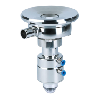
Page 25: Design
Design Design Designation Lantern Bellows Actuator Air connection Grooved cap nut Housing Housing connection... -
Page 26: Installation And Commissioning
Installation and Commissioning Notes on Installation Installation and Commissioning Notes on Installation The valve is fitted underneath the tank. Care must be taken to ensure that the valve housing and the pipe system can drain properly. To prevent damage, make sure that •... -
Page 27: Welding The Housing Connection Into The Tank
Installation and Commissioning Welding the Housing Connection into the Tank Welding the Housing Connection into the Tank This section describes how the housing connection is welded into the tank. When welding the housing connection (420) into the tank, the welding Requirement instructions (WPS) must be observed, see “Welding Instructions“... -
Page 28: Fitting The Valve With Detachable Pipe Connection Elements
Installation and Commissioning Pneumatic Connections Always close the housing before welding it into the pipe system and flush it with forming gas from the inside during the welding process. Weld the housing in position in the pipe, ensuring that the connection is free of stress and distortion. - Page 29 Installation and Commissioning Pneumatic Connections Air requirement for spring-to-close actuators (continued) Size Actuator type Actuator Air pressure Air pressure Air requirement diameter min. max. /stroke) (mm) at 1.01325 bar at 0°C as per DIN 1343 ISO 48.3 ECO-DZ B3 0.23 ISO 60.3 ECO-DZ D8 0.56...
-
Page 30: Establishing Hose Connections
Installation and Commissioning Electrical Connections Establishing Hose Connections To ensure reliable operation, the compressed air hoses must be cut exactly square. A hose cutter. Tools required: Carry out the following steps: Shut off the compressed air supply. Use the hose cutter to cut the pneumatic hoses square. Electrical Connections DANGER Live parts... -
Page 31: Commissioning
Installation and Commissioning Commissioning Commissioning Before starting commissioning observe the following: • Make sure that there are no foreign materials in the system. • Actuate the valve once by applying compressed air. • Clean the pipe system prior to the first product run. •... -
Page 32: Malfunctions
Malfunctions Malfunctions In the event of malfunctions immediately deactivate the tank bottom valve and secure it against inadvertent reactivation. Malfunctions may only be remedied by qualified staff, who must observe the safety instructions. Malfunction Cause Remedy Valve does not work Fault in the control system Check the system configu- ration No compressed air... -
Page 33: Maintenance
Maintenance Inspections Maintenance Inspections Between the maintenance periods, the tank bottom valve must be checked for leakage and proper function. Product Contact Seals Carry out the following steps: Regularly check the bellows. Pneumatic Connections Carry out the following steps: Check the operating pressure at the pressure reducing and filter station. Clean the air filter at regular intervals. -
Page 34: Maintenance Intervals
Maintenance Removing the Valve Maintenance Intervals To ensure the highest operational reliability of the tank bottom valves, all wearing parts should be replaced at longer intervals. The actual maintenance intervals can only be determined by the user since they depend on the operating conditions, for instance: •... -
Page 35: Disassembly
Maintenance Disassembly Disassembly This section describes disassembly of various components. Dismantling the Proximity Switch Mounting Carry out the following steps: Remove the proximity switches (I). Unscrew the switch bar (139). Unscrew (a/f 27) the proximity switch mounting (IH). Done. -
Page 36: Removing The Valve Insert
Maintenance Disassembly Removing the Valve Insert Raising the NOTE bellows High spring tension on the non-actuated valve (spring-to-close version) When releasing the grooved cap nut (252) there is a risk of the bellows and the round thread of the grooved cap nut being damaged. Before releasing the grooved cap nut (252) relieve the spring tension by energizing the actuator with compressed air. -
Page 37: Dismantling The Bellows
Maintenance Disassembly Withdrawing the NOTE valve insert from the housing The bellows is a sensitive component. Danger of damaging the bellows when pulling the valve insert from the housing (391). Carefully withdraw the valve insert from the housing. Do not set the valve insert down on the bellows. -
Page 38: Dismantling The Lantern
Maintenance Disassembly Dismantling the Lantern Carry out the following steps: Grip the actuator (140) with a belt wrench, release the valve stem (183) and remove it (a\f 24). Push up the grooved cap nut (252) and insert the round rod (8 mm in diameter) into the hole. -
Page 39: Maintenance
Maintenance Maintenance Remove the adapter (139) using an a\f 6 hex key. Done. Maintenance Cleaning the Valve Precision areas of the valve Bellows Housing Valve shaft NOTE Bellows (15), housing (391) and valve shaft (183) are precision areas. Damage to the valve can result in a malfunction. Observe the safety information sheets issued by the detergent manufac- turers! Only use detergents which are not aggressive towards the materials of... -
Page 40: Replacing Wearing Parts
Maintenance Maintenance Replacing Wearing Parts Always use original spare parts! Requirement Used seals must not be used again, since the proper function of the seal can then no longer be ensured! Carry out the following steps: Replace the bellows (15) if it is defective. Replace all seals and plain bearings identified in the diagram: (6) O-ring (29) O-ring... -
Page 41: Assembly
Maintenance Assembly Assembly Assembling the Position Indicator Carry out the following steps: Fit the adapter (139) using an a\f 6 hex key. Fit the O-ring (259) into the adapter (139) in accordance with the table “Position of the O-Ring in the Adapter“ (Page 41). Secure the mounting base (198) to the actuator (140) using a face spanner. -
Page 42: Assembling The Lantern
Maintenance Assembly Position of the O-ring (continued) Size Position of the O-ring (yellow) ISO 60.3 ISO 76.1 ISO 88.9 ISO 114.3 1 1/2"OD 2" OD 2 1/2" OD 3" OD 4" OD Assembling the Lantern Carry out the following steps: Grip the actuator (140) using a belt wrench and screw the lantern (9) into the actuator (140) by hand. -
Page 43: Fitting The Bellows
Maintenance Assembly Fitting the Bellows NOTE Damage to the bellows Damage to the bellows can result in malfunctions. Do not tension the bellows using a tool. When fitting, hold the bellows using a paper towel or a piece of leather. Carry out the following steps: Place the insert (261) on the valve stem (183). -
Page 44: Fitting The Valve Insert
Maintenance Assembly Fitting the Valve Insert In order that the valve insert can be fitted, the actuator must be in the Requirement open position. NOTE Sealing diaphragm is easily damaged Damage to the sealing diaphragm can result in malfunctions. Carefully introduce the bellows into the housing. Carry out the following steps: Pressurize the actuator (140) via (61). -
Page 45: Assembling The Proximity Switch Mounting
Maintenance Checking the Function Assembling the Proximity Switch Mounting Carry out the following steps: Screw (a\f 27) the proximity switch mounting (IH) on the actuator (140). Fit and adjust the proximity switches (I). Checking the Function Setting the Valve Stroke Carry out the following steps: Actuate the valve with compressed air. -
Page 46: Disposal
GEA Tuchenhagen accepts unopened actuators and arranges for proper disposal free of charge. Carry out the following steps: Remove the actuator, see “Disassembly“ (Page 35). Safely pack the actuator and send it to GEA Tuchenhagen GmbH. ® · VESTA XL Tank Bottom Valve Type H_A/T/F/M... -
Page 47: Technical Data
Technical Data Type Plate Technical Data Type Plate The type plate clearly identifies the valve. Type plate of the valve The type plate provides the following key data: Key data of the valve Type Tank Bottom Valve Type H_A/T/F/M VESTA Control air pressure min. -
Page 48: Technical Data
Technical Data Technical Data Technical Data The “Overview of Chemical Resistance“ for the PTFE material used is avail- able on request. The EPDM O-ring used on the valve to seal it off against the atmosphere may be used in the temperature range of -40°C to +135°C. Refer to the following tables for the key technical data of the valve: Technical data: Valve Designation... -
Page 49: Kv Values
Technical Data KV values Technical data: Compressed air supply Designation Description Air hose - Metric Material PE-LD Outside dia. 6 mm Inside dia. 4 mm - Inch Material PA Outside dia. 6.35 mm Inside dia. 4.3 mm Product pressure max. 6 bar / 87 psi Control air pressure NC actuator –... -
Page 50: Pipe Ends
Technical Data Pipe Ends Nominal width Kv value ISO 60.3 72.48 ISO 76.1 87.09 ISO 88.9 92.16 ISO 114.3 317.97 1.5" OD 29.54 2" OD 38.62 2.5" OD 76.71 3" OD 87.09 4" OD 151.39 Pipe Ends Dimensions for Pipes in DN Metric Outside diam- Wall thickness... -
Page 51: Tools
Technical Data Lubricants Dimensions for Pipes in ISO Outside diam- Wall thickness Inside diam- Outside diameter eter eter acc. to DIN 11866 Series B 42.4 42.4 38.4 48.3 48.3 44.3 60.3 60.3 56.3 76.1 76.1 72.1 88.9 88.9 84.3 114.3 114.3 109.7 Tools... -
Page 52: Spare Parts Lists
Spare Parts Lists Tank Bottom Valve type H_A/T/F/M Spare Parts Lists Tank Bottom Valve type H_A/T/F/M Control module types T.VIS Proximity switch mounting Proximity switch mounting ECO-E compl. 221-643.05 Item Designation Material Material no. Proximity switch mounting ECO-E 1.4301 221-643.04 O-ring 930-005 O-ring... - Page 53 Spare Parts Lists Tank Bottom Valve type H_A/T/F/M Control module types T.VIS M-1 and P-20 Item Designation Material Material no. 198.2 Mounting base compl. for T.VIS M-1 and P-20 221-589.32 O-ring 930-026 Plain bearing IGLIDUR-G 704-041 O-ring 930-046 129.2 Switch bar compl. for T.VIS M-1 1.4305 221-643.07 O-ring...
- Page 54 Spare Parts Lists Tank Bottom Valve type H_A/T/F/M Item Designation Material DN 40 DN 50 DN 65 DN 80 DN 100 Scheibe / washer 921-018 921-018 921-021 921-021 921-021 Round head grooved pin 925-092 925-092 925-092 925-092 925-092 Grooved cap nut H_A 1.4301 221-003932 221-003932 221-003933 221-003933 221-003934 *255 Thrust washer N_A/P...
- Page 55 Spare Parts Lists Tank Bottom Valve type H_A/T/F/M Item Designation Material “ OD 2" OD “ OD 3" OD 4" OD * Bellows T_A/P compl. 221-559.06 221-559.06 221-559.07 221-559.07 221-559.08 * Bellows T_A/P compl. 221-559.11 221-559.11 221-559.12 221-559.12 Sealing set H_A/M 221-003894 221-003894 221-003894 221-003894 221-003894 O-ring EPDM...
- Page 56 Spare Parts Lists Tank Bottom Valve type H_A/T/F/M Item Designation Material “ OD 2" OD “ OD 3" OD 4" OD Housing connection T_A 1.4404 221-555.02 221-555.02 221-555.03 221-555.03 221-555.04 1.4435 221-002943 221-002943 221-002944 221-002944 -- 1.4529 221-003299 221-003299 -- 1.4539 221-003300 221-003300 -- * Items 5, 15, (15.1), 184 and 255 are included in the bellows, compl.
- Page 57 Spare Parts Lists Tank Bottom Valve type H_A/T/F/M Item Designation Material ISO 42.2 ISO 48.3 ISO 60.3 * Bellows T_A/P compl. 221-559.06 221-559.06 221-559.07 * Bellows T_A/P compl. 221-559.11 221-559.11 221-559.12 Sealing set H_A/M 221-003894 221-003894 221-003894 O-ring EPDM 930-784 930-784 930-785 O-ring...
- Page 58 Spare Parts Lists Tank Bottom Valve type H_A/T/F/M Item Designation Material ISO 42.2 ISO 48.3 ISO 60.3 Housing connection T_A 1.4404 221-555.02 221-555.02 221-555.03 1.4435 221-002943 221-002943 221-002944 1.4529 221-003299 221-003299 1.4539 221-003300 221-003300 * Items 5, 15, (15.1), 184 and 255 are included in the bellows, compl. Items 6, 29, 59, 98 and 256 are included in the sealing set.
- Page 59 Spare Parts Lists Tank Bottom Valve type H_A/T/F/M Item Designation Material ISO 76.1 ISO 88.9 ISO 114.3 * Bellows T_A/P compl. 221-559.07 221-559.07 221-559.08 * Bellows T_A/P compl. 221-559.12 221-559.12 Sealing set H_A/M 221-003894 221-003894 221-003894 O-ring EPDM 930-785 930-785 930-786 O-ring 930-004...
- Page 60 Spare Parts Lists Tank Bottom Valve type H_A/T/F/M Item Designation Material ISO 76.1 ISO 88.9 ISO 114.3 Housing connection T_A 1.4404 221-555.03 221-555.03 221-555.04 1.4435 221-002944 221-002944 1.4529 1.4539 * Items 5, 15, (15.1), 184 and 255 are included in the bellows, compl. Items 6, 29, 59, 98 and 256 are included in the sealing set.
-
Page 61: Dimension Sheet - Tank Bottom Valve Type H_A/T/F/M
Spare Parts Lists Tank Bottom Valve type H_A/T/F/M Dimension Sheet – Tank Bottom Valve type H_A/T/F/M Nominal Dimensions widths ØD1 ØD2 ØD3 Weight Stroke HLA HTA HLA 45° DN 40 260.5 82.9 195.2 125 1.5 45.1 157.2 45.9 41.0 187 104.0 505.0 11.4 11.4 11.5 13.8... - Page 62 Spare Parts Lists Tank Bottom Valve type H_A/T/F/M Nominal Dimensions widths ØD1 ØD2 ØD3 Weight Stroke HLA HTA HLA 45° 88.9 289.0 108.8 229.7 125 2.3 79.3 240.9 72.4 88.9 237 169.5 653.0 27.0 26.4 27.6 22.0 114.3 309.7 125.1 250.4 125 2.3 95.0 283.2 83.6 114.3 267 169.5 738.7 35.4 33.8 36.5 28.1 1.5"...
-
Page 63: Welding Instructions
Welding Instructions Preparatory Information Welding Instructions Preparatory Information Preparatory Information Location Büchen Manufacturer's welding method TIG pulse Document no. Welder Certified acc. to DIN EN 287-1 and AD -2000 data sheet HP3 Welding process 141 DIN EN ISO 4063 Type of preparation Mechanical Type of cleaning Brushing or pickling... -
Page 64: Design Of The Joint / Welding Sequence
Welding Instructions Design of the Joint / Welding Sequence Design of the Joint / Welding Sequence Information on the Welding Sequence Vessel Housing Segment steps Welding bead Process Filler material Amperage Voltage Type of Ø [mm] current/polarity Electrode Root 1, 2 141 Pulse 90 - 110 11 - 14... -
Page 65: Fitting The Welding Device Prior To Welding
Welding Instructions Design of the Joint / Welding Sequence Fitting the Welding Device Prior to Welding Inside Housing connection Outside Welding device Fitting the welding device Nominal width Welding device DN40 / DN50 / ISO42.4 / ISO48.3 / 1.5" OD / 2" OD 229-103.54 DN65 / DN80 / ISO60.3 / ISO76.1 / ISO88.9 / 2.5"... -
Page 66: Explanation
Welding Instructions Design of the Joint / Welding Sequence ø Weld the second layer using filler (rod 1.2 mm) from the inside (layer 3) in segments, see section “Design of the Joint / Welding Sequence“. In contrast to root 2 start at position 1 of the segment steps, turned by 45°. - Page 67 Welding Instructions Design of the Joint / Welding Sequence...
- Page 68 Excellence · Passion · Integrity · Responsibility · GEA-versity GEA Group is a global engineering company with multi-billion euro sales and operations in more than 50 countries. Founded in 1881, the company is one of the largest providers of innovative equipment and process technology.
Need help?
Do you have a question about the VESTA XL H A and is the answer not in the manual?
Questions and answers