Table of Contents
Advertisement
Quick Links
Advertisement
Table of Contents

Subscribe to Our Youtube Channel
Related Manuals for GEA VARIVENT Vacuum Valve V


Summary of Contents for GEA VARIVENT Vacuum Valve V
- Page 1 Operating Instructions ® VARIVENT Vacuum Valve V Edition 2016-06-30 English...
- Page 2 This document is protected by copyright. All rights reserved. The document may not, in whole or in part, be copied, reproduced, translated or reduced to an electronic medium of machine-readable form without the express permission of GEA Tuchenhagen GmbH. ®...
-
Page 3: Table Of Contents
Table of Contents Notes for the Reader ............................5 Binding Character of These Operating Instructions ..................5 Notes on the Illustrations ..........................5 Symbols and Highlighting ..........................6 Abbreviations and Terms ..........................7 Safety ................................9 Safety Note ............................... 9 Operator's Duties .............................. - Page 4 Malfunctions ..............................27 Maintenance ..............................28 Inspections ..............................28 • Product Contact Seals ..........................28 • Pneumatic Connections ..........................28 • Electrical Connections ..........................29 Maintenance Intervals ............................. 29 Removing the Valve ............................29 Disassembling the Valve ..........................30 • Disconnecting the Valve from the Housing ....................
-
Page 5: Notes For The Reader
Notes for the Reader Notes on the Illustrations Notes for the Reader The present Operating Instructions are part of the user information for the valve. The Operating Instructions contain all the information you need to transport, install, commis- sion, operate and carry out maintenance for the valve. Binding Character of These Operating Instructions These Operating Instructions contain the manufacturer's instructions to the owner of the valve and to all persons who work on or use the valve regarding the procedures to... -
Page 6: Symbols And Highlighting
Notes for the Reader Symbols and Highlighting Symbols and Highlighting In these Operating Instructions, important information is highlighted by symbols or special formatting. The following examples illustrate the most important types of high- lighting. DANGER Warning: Fatal injuries. Failure to observe the warning can cause serious damage to health, or even death. ... -
Page 7: Abbreviations And Terms
Notes for the Reader Abbreviations and Terms IMPORTANT NOTE Warning: Damage to Property. Non-observance of the warning note can cause serious damage to the valve or the vicinity of the valve. The arrow identifies a precautionary measure you have to take to avoid the hazard. Carry out the following steps: = Start of a set of instructions. - Page 8 Notes for the Reader Abbreviations and Terms Abbreviation Explanation HNBR Material designation Short designation according to DIN/ISO 1629: Hydrogenated Acrylonitrile Butadiene Rubber Protection class International standard issued by the International Organization for Standardi- zation Unit of measurement of weight [kilogram] Unit of measurement of force [kilonewton] Unit of measurement of volume [litre] max.
-
Page 9: Safety
Safety Operator's Duties Safety Safety Note The valve is operationally reliable. It was built according to state-of-the art standards. Nevertheless, the valve can pose dangers, especially if • the valve is not used in accordance with its intended use, • the valve is not used correctly, •... -
Page 10: Qualification Of Staff
Safety Qualification of Staff Qualification of Staff This section contains information about the qualifications that staff working on the valve must have. Operating and maintenance staff must • have the necessary qualification to carry out their tasks, • be instructed with regard to possible dangers, •... -
Page 11: Supplementary Regulations
Safety Supplementary Regulations User groups (Cont.) Staff Qualifications Maintenance staff Adequate instruction as well as sound knowledge of the design and function of the valve. Sound knowledge in the following areas: • Mechanical equipment • Electrical equipment • Pneumatic system Authorization with regard to safety engineering standards to carry out the following tasks: •... -
Page 12: Instructions For The Safe Operation
Safety Instructions for the Safe Operation Instructions for the Safe Operation Dangerous situations during the operation can be avoided by safety-conscious and proactive behaviour of the staff. General Principles To ensure the safe operation of the valve the following principles apply: •... -
Page 13: Commissioning/Setup Mode
Safety Instructions for the Safe Operation Commissioning/Setup Mode For commissioning, the following principles apply: • Take protective measures against dangerous contact voltages in accordance with pertinent regulations. • The valve must be completely assembled and correctly adjusted. All screw connec- tions must be securely tightened. -
Page 14: Shutting Down
Safety Instructions for the Safe Operation Shutting Down For shutting down, the following principles apply: • Switch off the compressed air. • Switch off the valve via the main switch. • Padlock the main switch (if fitted) in the off position to prevent it from being switched back on. -
Page 15: Disassembly
Safety Instructions for the Safe Operation Disassembly For disassembly, the following principles apply: • Only allow qualified staff to disassemble the valve. • Before starting disassembly, the valve must be switched off and secured against being switched back on. Work may only be started once any residual energy has been discharged. -
Page 16: Signage
Safety Residual Risk Signage Dangerous points on the valve are indicated by warning signs, prohibition signs and mandatory signs. The signs and notes on the valve must always be legible. Any illegible signs must be replaced immediately. Signs on the valve Sign Meaning General hazard warning... -
Page 17: Residual Dangers
Safety Residual Risk Residual Dangers Dangerous situations can be avoided by safety-conscious and proactive behaviour of the staff and by wearing personal protective equipment. Residual dangers on the valve and measures Danger Cause Measure Danger to life Inadvertent switch-on of the valve Effectively disconnect all components, effectively prevent switch-on. -
Page 18: Declaration Of Incorporation
Safety Residual Risk Declaration of Incorporation Declaration of Incorporation in accordance with the EC Machinery Directive 2006/42/EC We herewith declare that this consignment contains the subsequently identified – but incomplete – machine and that putting into service is not permitted until it has been estab- lished that the machinery into which this machine is to be incorporated is in conformity with the provisions of the EC Machinery Directive. -
Page 19: Transport And Storage
Transport and Storage Storage Transport and Storage Scope of Supply On receipt of the valve check whether • the details on the type plate correspond to the data in the order and delivery docu- ments, • the equipment is complete and all components are in good order. Transport For transport, the following principles apply: •... -
Page 20: Intended Purpose
Intended Purpose Improper Operating Conditions Intended Purpose Designated Use The vacuum valve V is used for the automatic compensation of vacuum pressures in tanks or pipes. Since there is a risk that the valve disk may freeze at temperatures < 0°C, it is essential to equip the vacuum valve with a heating device. -
Page 21: Conversion Work
EC Machinery Direc- tive on your own. In general, only original spare parts supplied by GEA Tuchenhagen GmbH should be fitted. This ensures the reliable and economical operation of the valve. -
Page 22: Design
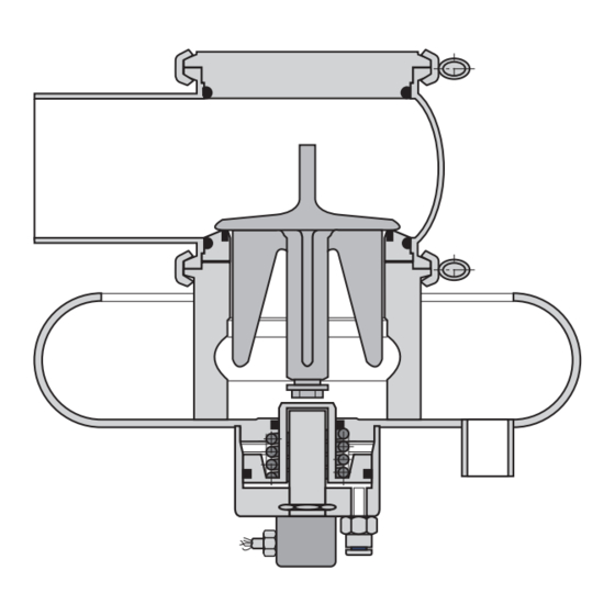
Design Design Fig. A: Type V... without feedback Fig. B: Type V...R with lifting actuator and feedback Fig. C: Type V...E without lifting; with feedback Fig. D: Type V...A with lifting; without feedback Item Designation Item Designation Valve disk V Disk Seat Square profile ring... -
Page 23: Installation And Commissioning
Installation and Commissioning Valve with Detachable Pipe Connection Elements Installation and Commissioning Notes on Installation To prevent damage, make sure that • the pressure in the tank/pipelines does not exceed 1 bar during valve lifting, as otherwise the piston will be damaged. This refers only to the component "piston". Please observe the safety note and the section on residual dangers, see chapter “Residual Dangers“... -
Page 24: Valve With Welding Ends
Installation and Commissioning Pneumatic Connections Valve with Welding Ends This section describes the welding procedure for the valve. IMPORTANT NOTE Seals are wearing parts Old seals will cause malfunction of the valve. When fitting the valve be sure to fit new housing O-rings. Carry out the following steps: Disassemble the valve, see chapter “Disassembling the Valve“... -
Page 25: Electrical Connections
Installation and Commissioning Electrical Connections Electrical Connections DANGER Live parts Electrical shock can result in serious personal injury or death. Only allow properly qualified staff to carry out work on the electrical equipment. Prior to establishing electrical connections check the maximum permissible oper- ating voltage. -
Page 26: Commissioning
Installation and Commissioning Commissioning Commissioning During commissioning and in other unpressurized processes in tanks or pipelines the vacuum valve opens if the tank/the pipe are emptied and solely the vacuum valve ensures pressure compensation. This effect can also occur during unpressurized cleaning. -
Page 27: Malfunctions
Malfunctions Malfunctions In the event of malfunctions immediately deactivate the valve and secure it against inad- vertent reactivation. Malfunctions may only be remedied by qualified staff, who must observe the safety instructions. Malfunction Cause Remedy Valve does not work Fault in the control system Check the system configuration No compressed air or Check the compressed air supply... -
Page 28: Maintenance
Maintenance Inspections Maintenance Inspections Between the maintenance periods, the valves must be checked for leakage and proper function. Product Contact Seals Carry out the following steps: Regularly check: – O-rings (5) in the cover (35) and seat (2) – Seal in the seat (2) ... -
Page 29: Electrical Connections
Maintenance Removing the Valve Electrical Connections Carry out the following steps: Check that the cap nut on the proximity switch is firmly secured. Check the cable connections on the heater and on the proximity switch. Done Maintenance Intervals To ensure the highest operational reliability of the valves, all wearing parts should be replaced at longer intervals. -
Page 30: Disassembling The Valve
Maintenance Disassembling the Valve Take the valve, with all housings and housing connections if possible, out of the pipe section. Done Disassembling the Valve Disconnecting the Valve from the Housing Type V... without feedback IMPORTANT NOTE Valve disk (1) and seat (2) are loose once the clamp joints (43) have been released. -
Page 31: Type V
Maintenance Disassembling the Valve Take off the clamp joints (43). Carefully pull the seat (2), the valve disk (1) and the complete vacuum housing (4) down and out of the housing (401). Done Type V... Without Feedback Carry out the following steps: ... -
Page 32: Type V
Maintenance Disassembling the Valve Type V...A With Lifting Actuator Carry out the following steps: Press the snap ring (9) together and pull off cylinder V (10). Type V...R With Lifting Actuator and Feedback Carry out the following steps: ... -
Page 33: Maintenance
Maintenance Maintenance Maintenance Cleaning the Valve CAUTION Cleaning agents spraying out due to excess pressure in the container to be cleaned If the container to be cleaned is under excess pressure, the pressure is released into the atmosphere during lifting. If this happens during cleaning, when cleaning solution is continuously sprayed into the valve housing, the air flowing out carries the cleaning solu- tion along. -
Page 34: Replacing Wearing Parts
Maintenance Maintenance Replacing Wearing Parts Carry out the following steps: Replace the O-rings (5) on seat. Replace the O-ring (12) on the vacuum housing. Replace snap ring (9) in valves with seat lifting. Remove the heater from the vacuum housing. Replace defective seals, but always fit new housing O-rings to ensure the tightness of the valve. -
Page 35: Lubricating Seals And Threads
They have the NSF- H1 (USDA H1) registration. PARALIQ GTE 703 can be ordered from GEA Tuchenhagen under part no. 413-064, and Rivolta F.L.G. MD-2 can be ordered under part no. 413- 071. -
Page 36: Setting The Proximity Switches
Maintenance Setting the Proximity Switches Torques to be set Torques lbft Clamp joints Cast clamps Clamp joints 16.2 Cast clamps Cast clamps Setting the Proximity Switches Vacuum Valve with Lifting Actuator Type V...R IMPORTANT NOTE Sensitive parts The piston can be slightly deformed when the proximity switch is fitted. ... -
Page 37: Vacuum Valve With Lifting Actuator Type V
Maintenance Setting the Proximity Switches Secure the proximity switch (15) using a hex. nut (15.1). After securing the proximity switch (15), there must be a gap of 1 to 1.5mm between areas (B) and (C) on the screw (19). If the gap is smaller or larger than 1 to 1.5mm, the screw (19) must be adjusted. -
Page 38: Disposal
Maintenance Disposal Secure the proximity switch (15) using a hex. nut (15.1). After securing the proximity switch (15), there must be a gap of 1 to 1.5mm between areas (B) and (C) on the screw (19). If the gap is smaller or larger than 1 to 1.5mm, the screw (19) must be adjusted. -
Page 39: Technical Data
Technical Data Technical Data Technical Data Type Plate The type plate clearly identifies the valve. Type plate of the valve The type plate provides the following key data: Key data of the valve Type Vacuum valve VLR Serial Serial number Material 1.4404 (AISI316L)/EPDM (FDA) Control air pressure bar/psi... - Page 40 Technical Data Technical Data Technical data: Valve (Cont.) Designation Description Material of product contact parts Stainless steel 1.4404 Polysulfone Check corrosion resistance with respect to media and detergents Installation position Vertical Heating wire Power 20 W Voltage 24 V AC Switching the power supply for heating on/off must be controlled externally.
-
Page 41: Resistance Of Sealing Materials
Technical Data Resistance of Sealing Materials Resistance of Sealing Materials The resistance of sealing materials depends on the type and temperature of the medium conveyed. The exposure time can adversely affect the service life of the seals. The sealing materials comply with the regulations of FDA 21 CFR 177.2600 or FDA 21 CFR 177.1550. -
Page 42: Pipe Ends
Technical Data Tools Pipe Ends Dimensions for Pipes in DN Metric Outside diameter Wall thickness Inside diam- Outside diameter eter acc. to DIN 11850 Dimensions for Pipes in Inch OD Inch OD Outside diameter Wall thickness Inside diameter Outside diameter acc. BS 4825 Part 1 2.5"... -
Page 43: Lubricants
Technical Data Weights Lubricants Lubricants Part no. Rivolta F.L.G. MD-2 413-071 PARALIQ GTE 703 413-064 Weights Size Weight (kg) DN 65, 80, 2.5", 3" approx. 6.0 DN 100, 4" approx. 8.2 DN 150, 6" IPS approx. 20... -
Page 44: Spare Parts Lists
221-257.01 221-257.01 221-257.01 221-257.02 Cylinder V 1.4301 221-258.01 221-258.01 221-258.01 221-258.02 Piston V PVDF/AL 221-259.01 221-259.01 221-259.01 221-259.02 GEA Mechanical Equipment GEA Tuchenhagen GmbH Am Industriepark 2-10, D-21514 Büchen, Germany Telephone +49 4155 49-0, Telefax +49 4155 49-2423 sales.geatuchenhagen@gea.com, http://www.tuchenhagen.com... - Page 45 930-257 O-ring Proximity switch PA12-GF30 505-083 505-083 505-083 Hex nut 910-149 910-149 910-149 Locking screw 922-080 922-080 922-080 GEA Mechanical Equipment GEA Tuchenhagen GmbH Am Industriepark 2-10, D-21514 Büchen, Germany Telephone +49 4155 49-0, Telefax +49 4155 49-2423 sales.geatuchenhagen@gea.com, http://www.tuchenhagen.com...
- Page 46 221-144.04 221-144.05 Clamp joint 14401 221-507.03 221-507.11 221-507.14 Housing V1 14404 221-101.35 221-101.36 221-101.17 Heater 221-590.03 221-590.04 221-590.05 GEA Mechanical Equipment GEA Tuchenhagen GmbH Am Industriepark 2-10, D-21514 Büchen, Germany Telephone +49 4155 49-0, Telefax +49 4155 49-2423 sales.geatuchenhagen@gea.com, http://www.tuchenhagen.com...
-
Page 47: Performance Curves
Spare Parts List Date: 2016-06-30 Page: 47 of 47 Spare_parts_lists.fm Vacuum Valve V Performance Curves GEA Mechanical Equipment GEA Tuchenhagen GmbH Am Industriepark 2-10, D-21514 Büchen, Germany Telephone +49 4155 49-0, Telefax +49 4155 49-2423 sales.geatuchenhagen@gea.com, http://www.tuchenhagen.com... -
Page 48: Dimension Sheet
3" IPS 4" IPS 6" IPS Ø 97.5 152,5 152,5 152,5 ØD ØF Stroke with disk Stroke without disk GEA Mechanical Equipment GEA Tuchenhagen GmbH Am Industriepark 2-10, D-21514 Büchen, Germany Telephone +49 4155 49-0, Telefax +49 4155 49-2423 sales.geatuchenhagen@gea.com, http://www.tuchenhagen.com... - Page 50 Excellence · Passion · Integrity · Responsibility · GEA-versity GEA Group is a global engineering company with multi-billion euro sales and operations in more than 50 countries. Founded in 1881, the company is one of the largest providers of innovative equipment and process technology.
Need help?
Do you have a question about the VARIVENT Vacuum Valve V and is the answer not in the manual?
Questions and answers