
Related Manuals for GEA VARINLINE


Summary of Contents for GEA VARINLINE
- Page 1 Hygienic valves ® GEA VARINLINE Housing Installation instruction (Translation from the original language) 430BAL008619EN_3...
- Page 2 EU Machinery Directive. This document is protected by copyright. All rights reserved. The document may not, in whole or in part, be copied, reproduced, translated or reduced to an electronic medium of machine-readable form without the express permission of GEA Tuchenhagen GmbH.
-
Page 3: Table Of Contents
TABLE OF CONTENTS ® Assembly Instructions VARINLINE Housing Safety instructions Pressure equipment directive Removing the housing Maintenance Assemble the housing ® Spare parts list - VARINLINE housing Dimension sheet - in-line housing 430BAL008619EN_3 29.02.2024... - Page 4 430BAL008619EN_3 29.02.2024...
-
Page 5: Assembly Instructions Varinline
® Assembly Instructions VARINLINE Housing Safety instructions ® Assembly Instructions VARINLINE Housing Safety instructions Maintenance and repair Before carrying out maintenance and repair work on the component's electrical equipment, perform the following steps in accordance with the "5 safety rules": •... -
Page 6: Pressure Equipment Directive
® Assembly Instructions VARINLINE Housing Pressure equipment directive • Mark the lines (if unmarked) prior to disassembly to ensure they are not confused when re- assembling. • Protect open line ends with blind plugs against ingress of dirt. • Pack sensitive parts separately. -
Page 7: Assemble The Housing
There must be no objects (tools, cleaning rags, cleaning agents) in the pipe before installing the in-line housing. • The installation position must ensure that the VARINLINE housing can safely run empty. For in-line housings with welding supports, proceed as follows: Basically weld in-line housings free of stress and distortion with mounted blanking plates and hinged rings, but without O-rings. - Page 8 ® Assembly Instructions VARINLINE Housing Tighten the nuts of the hinged rings with the following torque: – M6 9 Nm (6.6 lb ft) – M8 22 Nm (16.2 lb ft) ® The housing is assembled. 430BAL008619EN_3 29.02.2024...
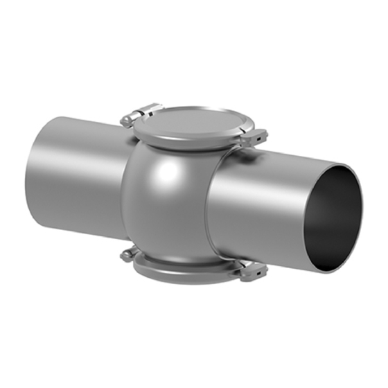
- Page 9 ® Spare parts list - VARINLINE housing ® Spare parts list - VARINLINE housing Fig.1: * pos. 43.1 clamp connection DE to break down possible internal pressures 430BAL008619EN_3 29.02.2024...
-
Page 10: Spare Parts List - Varinline
® Spare parts list - VARINLINE housing Item Designation Process connection Material O-ring EPDM 930-270 930-270 930-309 930-144 930-144 930-144 930-144 930-163 930-163 930-168 930-171 930-171 930-171 930-171 HNBR 930-637 930-637 930-632 930-633 930-633 930-633 930-633 PTFE 930-181 930-181 930-188... - Page 11 ® Spare parts list - VARINLINE housing Item Designation Process connection 1" 1.5" 2" 2.5" 3" 4" 6" 4" 6" Material O-ring EPDM 930-309 930-144 930-144 930-144 930-144 930-144 930-144 930-156 930-156 930-168 930-171 930-171 930-171 930-171 930-171 930-171 930-178...
-
Page 12: Dimension Sheet - In-Line Housing
Dimension sheet - in-line housing Dimension sheet - in-line housing Fig.2 430BAL008619EN_3 29.02.2024... - Page 13 Dimension sheet - in-line housing Process connection Ø Ø1 H ** 68.5 71.5 X ** 37.5 43.5 Process connection 1" 1.5" 2" 2.5" 3" 4" 6" 4" 6" Ø 22.2 34.9 47.6 60.3 97.4 146.9 97.4 146.9 Ø1 25.4 38.1 50.8 63.5 76.2...
Need help?
Do you have a question about the VARINLINE and is the answer not in the manual?
Questions and answers