
Related Manuals for Yetter MAGNUM 10000 Series


Summary of Contents for Yetter MAGNUM 10000 Series
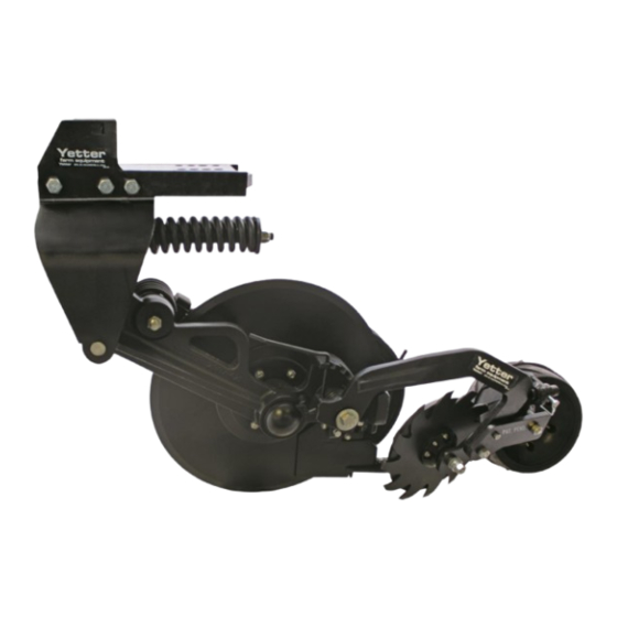
- Page 1 ™ 10000 SERIES MAGNUM FERTILIZER COULTER 2565-957_Rev_M 08/2024 YETTER MANUFACTRURING CO. Founded 1930 Colchester, IL 62326-0358 Toll free: 800-447-5777 Fax: 309-776-3222 Website: www.yetterco.com Email: info@yetterco.com...
- Page 4 TABLE OF CONTENTS Foreword ..................... 2 Safety…………………………………………………………………………2-3 Torque ......................5 General Information ................. 6-7 Assembly Instructions ................8-9 Operation ....................10-12 Troubleshooting ..................13 Maintenance ..................14-18 Part Identification ................19-51 CAUTION: The 10000 Series Magnum coulters are very heavy. Pay extra attention to lifting techniques when handling or maneuvering the coulter during assembly.
-
Page 5: Bolt Torque
BOLT TORQUE ™ Before operating the 10000 Series Magnum for the first time, check to be sure that all hardware is tight. Check all hardware again after approximately 50 hours of operation and at the beginning of each planting season. ™... -
Page 6: General Information
GENERAL INFORMATION 10000 Series Magnum Fertilizer Coulter STANDARD FEATURES FOR ALL MODELS High application speeds with minimal soil disturbance for fall, pre- plant, and side-dressing applications Tube kits for applying liquid, dry, or anhydrous All cast design ... - Page 7 GENERAL INFORMATION 10000 Magnum Fertilizer Coulter...
- Page 8 Example: A 30’ – 3 section toolbar with 12 coulters (6R & 6L) will need to install 2R and 2L coulters on each section of the toolbar. If any questions concerning assembly of coulters, then please contact Yetter Farm Equipment for recommendations at 800-447-5777.
- Page 9 ASSEMBLY INSTRUCTIONS STEP 2: Attach the 10000 Series Magnum to the toolbar using the appropriate clamp and hardware. HARDWARE KITS PART IDENTIFICATION...
- Page 10 OPERATION INSTRUCTIONS TOOLBAR FRAME HEIGHT ADJUSTMENT Adjusting Opener Depth: -Raise toolbar frame for shallow application -Lower toolbar frame for deeper application Figure A: The toolbar height is set to 25” above the soil surface. To ensure that frame heights are correct, it is important measurements are taken before use. Figure B: The hitch is set too low while the toolbar is not parallel with the soil surface.
- Page 11 OPERATION INSTRUCTIONS 10000 MAGNUM CLOSING WHEEL DOWNFORCE ADJUSTMENT...
- Page 12 OPERATION INSTRUCTIONS 10000 MAGNUM WHEEL SEALER DEPTH ADJUSTMENT...
- Page 13 OPERATION INSTRUCTIONS Troubleshooting the 10000 Series Magnum Coulter Symptom Problem Solution Too much down pressure Remove spring pressure Mud builds up on press from press wheels wheels and wheels stop turning Field is too wet Wait until field dries before running Hard ground conditions Add weights to toolbar...
-
Page 14: Maintenance
MAINTENANCE Practice Safety Understand and practice safe service procedures before doing work. Follow ALL the operating, maintenance, and safety information in the equipment operator’s manual. Clear the area of bystanders, especially small children, when performing any maintenance or adjustments. Keep work area clean and dry. Use adequate lighting for the job. - Page 15 MAINTENANCE Lubrication Intervals Lubricate with grease at hourly interval indicated on symbol. The recommended service intervals are based on normal oberating conditions. Severe or unusual conditions may requre more frequent lubrication. Perform each lubrication and service procedure at the beginning of each season. Clean grease fittings before using grease gun to avoid injecting dirt and grit into the bearing.
- Page 16 Alternative Lubricants Conditions in certain geographical areas may require special lubricants and lubrication practices which do not appear in the operator’s manual. If there are any questions, consult Yetter Manufacturing Co. to obtain the latest information and reccomendations. Part # Description...
- Page 17 Clean machine thoroughly to remove all dirt, debris, and crop residue. Inspect machine for worn or broken parts. See your Yetter Farm Equipment dealer during the off-season so parts and service can be acquired when the machine is not needed in the field.
- Page 18 MAINTENANCE BEARING ADJUSTMENT: 1. Raise the toolbar until the blade is clear of the ground. Place a safety stand under the toolbar. Remove the blade. Remove the hub cap, cotter pin, slotted nut, washer and spacer from the spindle shaft assembly. 2.
- Page 19 ¾-10 TOP LOCK HEX NUT GR. C 2526-451 5/8 FLAT WASHER WASHER 21/32” ID. X 1-1/4” OD. X ¼” THICK 2526-455 2565-071 PATENT DECAL 2565-162 YETTER DECAL 2987-142-L LH CAST CLOSER WHEEL ASSEMBLY 6200-363 6.5 X 12 PRESS WHEEL ASSEMBLY 2570-069 40MM BEARING 10000-100-LH...
- Page 20 ¾-10 TOP LOCK HEX NUT GR. C 2526-451 5/8 FLAT WASHER 2526-455 WASHER 21/32 ID. X 1-1/4 OD. X ¼ THK 2565-071 PATENT DECAL 2565-162 YETTER DECAL 2987-142-L LH CAST CLOSING WHEEL ASSEMBLY 6200-363 6.5 X 12 PRESS WHEEL ASSEMBLY 2570-069 40MM BEARING 10000-100-LH LH BASE ASSEMBLY 4”...
- Page 21 5/8-11 TOP LOCK HEX NUT GR. C 2520-604 ¾-10 TOP LOCK HEX NUT GR. C 2526-455 WASHER 21/32 ID. X 1-1/4 OD. X ¼ THK 2565-162 YETTER DECAL 2987-142-L LH CAST CLOSING WHEEL ASSEMBLY 10000-100-LH LH BASE ASSEMBLY 10000-200 TOOLBAR MOUNT 4,5,6,7...
- Page 22 5/8-11 TOP LOCK HEX NUT GR. C 2520-604 ¾-10 TOP LOCK HEX NUT GR. C 2526-455 WASHER 21/32 ID. X 1-1/4 OD. X ¼ THK 2565-162 YETTER DECAL 2987-142-L LH CAST CLOSING WHEEL ASSEMBLY 10000-100-LH LH BASE ASSEMBLY 10000-201 TOOLBAR MOUNT 4 INCH...
- Page 24 MANUFACTURED 7/2016 – 2/2018...
- Page 25 MANUFACTURED 7/2016 – 2/2018...
- Page 26 PART IDENTIFICATION 10000-100-LH ITEM PART NO. DESCRIPTION 2502-206 5/16-18 X 1-1/2 HHCS GRADE 5 2502-244 3/8-16 X 1-1/4 HHCS GRADE 5 2502-296 ½-13 X 2-1/2 HHCS GRADE 5 2502-327 5/8-11 X 5 HHCS GRADE 5 2502-351 ½-13 X 2 HHCS GRADE 5 2502-405 ¾-10 X 8 HHCS GRADE 5 2502-426...
- Page 27 PART IDENTIFICATION 10000-100-LH MANUFACTURED 3/2018 - PRESENT...
-
Page 28: Part Identification
PART IDENTIFICATION 10000-100-RH ITEM PART NO. DESCRIPTION 2502-206 5/16-18 X 1-1/2 HHCS GRADE 5 2502-244 3/8-16 X 1-1/4 HHCS GRADE 5 2502-296 ½-13 X 2-1/2 HHCS GRADE 5 2502-327 5/8-11 X 5 HHCS GRADE 5 2502-351 ½-13 X 2 HHCS GRADE 5 2502-405 ¾-10 X 8 HHCS GRADE 5 2502-426... - Page 29 PART IDENTIFICATION 10000-100-RH...
- Page 30 PART IDENTIFICATION 10000-111-LH (SHOWN) 10000-111-RH ITEM PART NO. DESCRIPTION 2502-198 5/16-18 X 1 HHCS GRADE 5 2525-201 5/16 LOCKWASHER 2526-562 1-17/64 ID X 2-1/4 OD X 10 GAUGE MACHINE BUSHING 2531-124 3/16 X 2 COTTER PIN 2533-110 ¼-28 GREASE FITTING STRAIGHT SELF-TAP 2550-056 CUP, KOYO #2729 2550-057...
- Page 31 PART IDENTIFICATION 10000-111-LH (SHOWN) 10000-111-RH ITEM PART NO. DESCRIPTION 2502-198 5/16-18 X 1 HHCS GRADE 5 2525-201 5/16 LOCKWASHER 2526-562 1-17/64 ID X 2-1/4 OD X 10 GAUGE MACHINE BUSHING 2531-124 3/16 X 2 COTTER PIN 2533-110 ¼-28 GREASE FITTING STRAIGHT SELF-TAP 2550-056 CUP, KOYO #2729 2550-057...
- Page 32 MANUFACTURED 06/2016 – 06-2023...
- Page 33 PART IDENTIFICATION 10000-112A WIPER WHEEL ARM ASSEMBLY ITEM PART NO. DESCRIPTION 10000-303 WIPER WHEEL ARM 10000-316 SLEEVE 1.5 OD X 1.25 ID X 1.50 WIDTH MANUFACTURED 06/2023 – PRESENT...
- Page 34 PART IDENTIFICATION 10000-113-LH(SHOWN) AND 10000-113-RH CLOSING WHEEL ARM ASSEMBLY ITEM PART NO. DESCRIPTION 10000-304 LEFT HAND CLOSE WHEEL ARM (SHOWN) 10000-305 RIGHT HAND CLOSE WHEEL ARM 10000-318 SLEEVE 1.50 OD X 1.25 ID X 2.70 WIDTH...
- Page 35 10000-114 07/2016-07/2023 6000-071 08/2023-PRESENT 2502-229 FLANGE HEAD BOLT M8X1.25X25MM 6000-600 THREE SPOKE HUB 4.5”X16 TIRE 2520-208 FLANGE HEX NUT 6000-602 2550-527 SNAP RING 6000-604 WHEEL HALF 2570-069 40MM BEARING 6000-605 INNER WHEEL HALF...
- Page 36 ITEM PART NO. DESCRIPTION QTY. 2502-225 5/16-18 X 1-1/2 HHFS GR. 5 2571-286 SHARKTOOTH WHEEL HUB ASSEMBLY 2.406” SPINDLE 2965-501 2965-503 HUB CAP 2987-396 CAST PRESS WHEEL MANUFACTURED 06/2021 – PRESENT...
- Page 37 ITEM PART NO. DESCRIPTION QTY. 2502-209 5/16-18 X 1-13/4 GR. 5 2520-206 5/16-18 FLANGE LOCK NUT 2570-594 BEARING D-BOLT FLANGED 5/8-11 X 3.812” GR. 8 2570-742 2965-128 HUB ASSEMBLY 2550-069 SEAL 2570-594 BEARING 2570-715 INSERT 2965-351 2965-352 HUB CAP 13” SHARK TOOTH 2967-602 2987-396 PRESS WHEEL...
- Page 38 PARTS IDENTIFICATION 2965-120 HUB UPDATE KIT ITEM PART NO. DESCRIPTION QTY. 2502-225 5/16-18 X 1-1/2 HHFS GR. 5 HUB ASSEMBLY 2.406” SPINDLE 2965-501 2940-560 SET SCREW .313-18 X .75...
- Page 39 PARTS IDENTIFICATION 10000-080-LH RESIDUE MANAGER MOUNT KIT...
- Page 40 PARTS IDENTIFICATION 10000-080-RH RESIDUE MANAGER MOUNT KIT...
- Page 41 PARTS IDENTIFICATION 10000-117 LEFT HAND MAGNUM OFFSET KIT...
- Page 42 PARTS IDENTIFICATION 10000-118 LEFT HAND MAGNUM OFFSET KIT...
- Page 52 2565-957_Rev_M 08/2024...
Need help?
Do you have a question about the MAGNUM 10000 Series and is the answer not in the manual?
Questions and answers