Advertisement
Quick Links
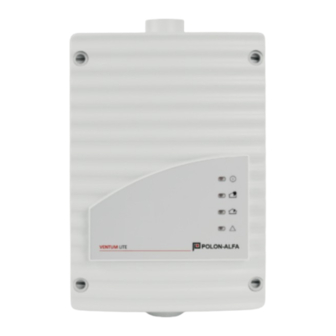
Installation Instructions
Aspirating smoke detector
VENTUM PRO LITE SL
VENTUM PRO LITE TWO SL
1
Operating indicator light
2
Alarm indicator light for detector
module II
3
Alarm indicator light for detector
module I
4
Indicator light for common fault
5
Prepunched cable entries for
connection to the central fire panel
or power supply (input/output)
6
Connection pipe system I
7
Connection pipe system II
8
Connection for air return
Instrukcja instalacji
Zasysająca czujka dymu
VENTUM PRO LITE SL
VENTUM PRO LITE TWO SL
1
Lampka kontrolna zadziałania
2
Lampka kontrolna alarmu dla modułu
detekcyjnego II
3
Lampka kontrolna alarmu dla modułu
detekcyjnego I
4
Lampka kontrolna dla uszkodzenia
zbiorczego
5
Przepusty kablowe do podłączenia
do centrali systemu sygnalizacji
pożaru lub zasilania (wejście /
wyjście)
6
Podłączenie rurociągu I
7
Podłączenie rurociągu II
8
Wylot powietrza z czujki zasysającej
(podłączenie rury powrotnej)
II-E392-002
1/9
Advertisement

Related Manuals for Polon-Alfa VENTUM PRO LITE SL


Summary of Contents for Polon-Alfa VENTUM PRO LITE SL
- Page 1 II-E392-002 Instrukcja instalacji Installation Instructions Zasysająca czujka dymu Aspirating smoke detector VENTUM PRO LITE SL VENTUM PRO LITE SL VENTUM PRO LITE TWO SL VENTUM PRO LITE TWO SL Operating indicator light Lampka kontrolna zadziałania Alarm indicator light for detector Lampka kontrolna alarmu dla modułu...
- Page 2 II-E392-002 Installation of the Detector Module Instalacja modułu detekcyjnego Please note: Uwaga: Only approved detector modules of the type Wolno stosować tylko dedykowane moduły DM-TF-01, DM-TF-10 and DM-TF-50 may be detekcyjne typu DM-TF-01, DM-TF-10 i DM-TF- used. 1. Carry out the following works only if the 1.
- Page 3 II-E392-002 5. Break carefully the clasp for the connection 5. Ostrożnie wyłam śrubokrętem blokadę do of the second pipe system (predetermined podłączenia drugiego rurociągu zasysają- breaking point, marked by “II“) with a cego -miejsce oznaczone „II”. screwdriver from the housing. Note: Uwaga: The knocked clasp is to removed completely...
- Page 4 II-E392-002 Setting the response sensitivity Ustawienie czułości detector module Moduł detekcyjny DM-TF-50 DM-TF-10 DM-TF-01 DM-TF-50 DM-TF-10 DM-TF-01 0,8 %/m 0,12 %/m 0,8 %/m 0,12 %/m 0,4 %/m 0,06 %/m 0,4 %/m 0,06 %/m 1,0 %/m 0,2 %/m 0,03 %/m 1,0 %/m 0,2 %/m 0,03 %/m 0,5 %/m...
- Page 5 II-E392-002 Choose number of the detector modules Wybór liczby modułów detekcyjnych The number of the stocked detector modules Liczbę modułów czujek wybiera się za pomocą are chosen with the jumper JU4. The following zworki JU4. Poniższa tabela pokazuje ustawienia table shows, whether the jumper must be put zworek: or not: X = pin pair bridge...
- Page 6 II-E392-002 Setting the ventilator voltage Ustawienie napięcia wentylatora main- additional płyta dodatkowa board board główna płyta Jumper BR 1 BR 2 Zestyk BR 1 BR 2 Pin No. 1 + 2 1 + 2 1 + 2 zworki nr 1 + 2 1 + 2 1 + 2 6,5 V...
- Page 7 II-E392-002 Installation of the device Instalacja urządzenia General information: Informacje ogólne: When choosing the installation location Wybierając miejsce instalacji, upewnij się, make sure the displays of the device are że wyświetlacz urządzenia jest dobrze clearly visible. widoczny. Screw the air sampling smoke detection Przykręć...
- Page 8 II-E392-002 M25, 1x M20 included in the delivery) by dole obudowy (na wyposażeniu króćce inserting them into the corresponding cable plastikowe 2x M25, 1x M20). entry/entries. 5. Przeprowadź kable (przekrój żył maks. 1,5 5. Pass the connection cable(s) (max. 1.5 mm²) mm²) wymagane do okablowania urządzenia required to wire the device through the przez odpowiednie przepusty i przytnij je na...
- Page 9 II-E392-002 Connection Przyłącza X6, 1 contact of the first alarm X6, 1 zestyk 1 przekaźnika relay (make contact) alarmowego (styk X6, 2 center tap of first alarm zwierny) relay X6, 2 wspólny styk przekaźnika X6, 3 contact of the first alarm alarmu 1 stopnia relay (break contact) X6, 3...
- Page 10 II-E392-002 Commissioning Uruchomienie 1. Switch on the voltage supply (24 V) of the 1. Podłącz urządzenie do zasilania (24 V). device. Note: Uwaga: The fan of the device starts running only Wentylator urządzenia zacznie pracować po 15 15 seconds after switching on the voltage sekundach od podłączenia zasilania (24 V).
Need help?
Do you have a question about the VENTUM PRO LITE SL and is the answer not in the manual?
Questions and answers