Polon-Alfa VENTUM PRO LITE Installation Instructions Manual
Aspirating smoke detector
Hide thumbs
Also See for VENTUM PRO LITE:
- Installation instructions (3 pages) ,
- Technical manual (250 pages)
Advertisement
Quick Links
Installation Instructions
Aspirating smoke detecctor
VENTUM PRO LITE
VENTUM PRO LITE TWO
1
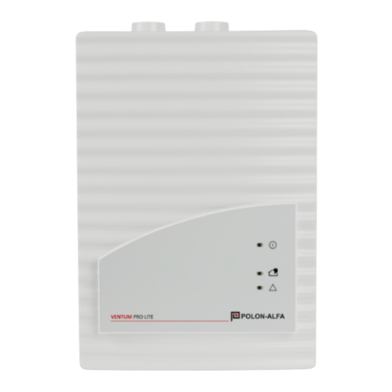
Operating indicator light
2
Alarm indicator light for detector
module II
3
Alarm indicator light for detector
module I
4
Indicator light for common fault
5
Prepunched cable entries for
connection to the central fire panel
or power supply (input/output)
6
Connection pipe system I
7
Connection pipe system II
8
Connection for air return
Instrukcja instalacji
Zasysająca czujka dymu
VENTUM PRO LITE
VENTUM PRO LITE TWO
1
Lampka kontrolna zadziałania
2
Lampka kontrolna alarmu dla modułu
detekcyjnego II
3
Lampka kontrolna alarmu dla modułu
detekcyjnego I
4
Lampka kontrolna dla uszkodzenia
zbiorczego
5
Przepusty kablowe do podłączenia
do centrali systemu sygnalizacji
pożaru lub zasilania (wejście /
wyjście)
6
Podłączenie rurociągu I
7
Podłączenie rurociągu II
8
Wylot powietrza z czujki zasysającej
(podłączenie rury powrotnej)
II-E392-001
1/9
Advertisement

Subscribe to Our Youtube Channel
Related Manuals for Polon-Alfa VENTUM PRO LITE


Summary of Contents for Polon-Alfa VENTUM PRO LITE
- Page 1 Instrukcja instalacji Installation Instructions Zasysająca czujka dymu Aspirating smoke detecctor VENTUM PRO LITE VENTUM PRO LITE VENTUM PRO LITE TWO VENTUM PRO LITE TWO Operating indicator light Lampka kontrolna zadziałania Alarm indicator light for detector Lampka kontrolna alarmu dla modułu...
- Page 2 II-E392-001 Installation of the Detector Module Instalacja modułu detekcyjnego Please note: Uwaga: Only approved detector modules of the type Wolno stosować tylko dedykowane moduły DM-TF-01, DM-TF-10 and DM-TF-50 may be detekcyjne typu DM-TF-01, DM-TF-10 i DM-TF- used. 1. Carry out the following works only if the 1.
- Page 3 II-E392-001 ventilator cover for the second air sampling tylatora z drugiego kanału wlotowego (sa- duct (self-adhesive plastic cover). Take for moprzylepna plastikowa osłona). W razie this if necessary a screwdriver. potrzeby użyj śrubokręta. Wszystkie po- 5. Break carefully the clasp for the connection niższe prace należy wykonywać...
- Page 4 II-E392-001 Setting the response sensitivity Ustawienie czułości detector module Moduł detekcyjny DM-TF-50 DM-TF-10 DM-TF-01 DM-TF-50 DM-TF-10 DM-TF-01 0,8 %/m 0,12 %/m 0,8 %/m 0,12 %/m 0,4 %/m 0,06 %/m 0,4 %/m 0,06 %/m 1,0 %/m 0,2 %/m 0,03 %/m 1,0 %/m 0,2 %/m 0,03 %/m 0,5 %/m...
- Page 5 II-E392-001 Choose number of the detector modules Wybór liczby modułów detekcyjnych The number of the stocked detector modules Liczbę modułów czujek wybiera się za pomocą are chosen with the jumper JU4. The following zworki JU4. Poniższa tabela pokazuje, usta- table shows, whether the jumper must be put wienia zworek: or not: X = pin pair bridge...
- Page 6 II-E392-001 Device Supports Blachy montażowe Support type MT-1 Blachy montażowe typ MT-1 horizontal installation mocowane poziomo Support type MT-1 Blachy montażowe typ MT-1 vertical installation mocowane pionowo Installation of the device Instalacja urządzenia General information: Informacje ogólne: Wybierając miejsce instalacji, upew- When choosing the installation location nij się, że wyświetlacz urządzenia jest make sure the displays of the device are...
- Page 7 II-E392-001 guarantee a safe fixing and to limit vibrations na ścianie i maks. ᴓ 4 mm przy which occur. montażu za pomocą wspornika MT-1) 2. Fix the device by means of four screws in w celu zapewnienia bezpiecznego accordance with the mounting type to the mocowania i ograniczenia wall or the device support.
- Page 8 II-E392-001 Connection Przyłącza X6, 1 contact of the first alarm X6, 1 zestyk 1 przekaźnika relay (make contact) alarmowego (styk zwierny) X6, 2 center tap of first alarm X6, 2 wspólny styk przekaźnika relay alarmu 1 stopnia zetyk 1 przekaźnika contact of the first alarm X6, 3 X6, 3...
- Page 9 II-E392-001 X7, 8 fault contact first detector X7, 8 zestyk usterki modułu module detekcyjnego 1 (połączenie X7, 9 (connection 1) X7, 9 fault contact first detector zestyk usterki modułu module detekcyjnego 1 (połączenie (connection 2) Commissioning Uruchomienie 1. Make sure first that the device has been in 1.
Need help?
Do you have a question about the VENTUM PRO LITE and is the answer not in the manual?
Questions and answers