
Related Manuals for Polon-Alfa POLON 4000 DOP-6001


Summary of Contents for Polon-Alfa POLON 4000 DOP-6001
- Page 1 IK-E343-001E POLON 4000 INTERACTIVE FIRE DETECTION AND ALARM SYSTEM DOP-6001 OPTICAL BEAM SMOKE DETECTOR Installation and maintenance manual IK-E343-001E Edition I...
- Page 2 Read the manual carefully before the detector assembling and commissioning. Any nonconformity with the instructions contained in the manual may be harmful or may cause violation of the law in force The manufacturer, POLON-ALFA shall not bear responsibility for any harms resulted from the unit application discordantly to the requirements of this instruction.
-
Page 3: Technical Specifications
IK-E343-001E 1 PURPOSE The DOP-6001 Beam Smoke Detector is designed for smoke detection at the start of a fire. It is especially suitable for protection of premises where, in the first phase of the fire, smoke appearance is expected and in which, due to a large space area, installation of a greater number of spot smoke detectors would be necessary. -
Page 4: Principle Of Operation
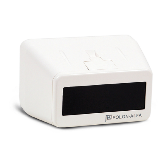
IK-E343-001E Fig. 1. DOP-6001 detector with prism reflector PRINCIPLE OF OPERATION The DOP-6001 detector consists of an infrared (IR) light transmitter and a receiver located in a single enclosure, and an interoperating separate E39-8R prism reflector or 4xE39-8R reflector panel. The detector principle of operation consists in continuous analysis of optical air transparency in a space between the detector and the reflector (reflector panel). -
Page 5: Installation
IK-E343-001E ambient temperature and the settled sensitivity threshold. A self-adjustment program is switched on after entering these data into the detector memory. The self-adjustment process terminates after achieving a reference value with 5 % tolerance. Afterwards, the decision criteria are drawn up for various fire phenomena runs, for instance for fast or slow fire development. - Page 6 IK-E343-001E mounted on opposite walls, pillars or other construction elements of the premises. The walls or pillars must be stable and vibration-free. The detector adjustment basis should be mounted on a wall and the reflector/reflector panel - on the opposite wall. The detector should be placed on the adjustment basis (Fig. 3) after preliminary connection of the wires to the connecting blocks in accordance with Fig.
-
Page 7: Safety Conditions
Any maintenance works or periodic inspection shall be executed by skilled personnel employed by companies being authorised or trained by POLON-ALFA. Any repairs must be carried out by the manufacturer. POLON-ALFA bears no responsibility for the operation of any apparatus being serviced and repaired by unauthorised personnel. -
Page 8: Storage And Transport
IK-E343-001E STORAGE AND TRANSPORT The detectors should be stored in closed premises at ambient temperature ranging from 0 C to +40 C and relative humidity up to 80 % at +35 C, free from volatile sulphur compounds as well as acid and alkaline vapours. - Page 9 IK-E343-001E Fig. 3. DOP-6001 design and overall dimensions Note: Only one detector (without an end-of-line resistor) can be installed in a conventional detection line, therefore no line output to the next detector is provided.
- Page 10 IK-E343-001E Fig. 4. DOP-6001 detector installation wires connection Fig. 5. DOP-6001 detector internal connections and output terminals diagram...
- Page 11 IK-E343-001E Declared sensitivity levels: - jumper in position 50 % – low sensitivity - jumper in position 30 % – medium sensitivity - jumper in position 18 % – high sensitivity In the case of the POLON 4000 addressable system, a sensitivity threshold is declared in the control panel and all jumpers should be taken out.
- Page 12 IK-E343-001E Fig. 8. Reflector panel...
- Page 13 IK-E343-001E Fig. 9. DOP-6001 detector testing foil with overprints...
- Page 14 IK-E343-001E Fig. 10. Reflector panel assembly IK-E343-001E/03.2012/04.2012...
Need help?
Do you have a question about the POLON 4000 DOP-6001 and is the answer not in the manual?
Questions and answers