
Related Manuals for Polon-Alfa ADR-20R


Summary of Contents for Polon-Alfa ADR-20R
- Page 1 ADR-20R OPTICAL SMOKE DETECTOR for burglar alarm systems _________________________________________________________________________________ INSTALLATION AND MAINTENANCE MANUAL IK-E289-001GB IIIK Edition...
- Page 2 Any nonconformity with the instructions contained in the manual may be harmful or may cause violation of the law in force POLON-ALFA shall not bear responsibility for any harms resulted from the unit application discordantly to the requirements of this instruction.
-
Page 3: Technical Specifications
IK-E289-001GB 1 PURPOSE The ADR-20R optical smoke detector is designed for detection of a visible smoke that is concurrent with most fire combustion. It is dedicated to monitor a fire hazard in facilities equipped with burglar alarm systems. The detector is power supplied from a burglar alarm control panel. An alarm signal is transferred to the control panel or another signalling device using relay contacts. -
Page 4: General Descriptions
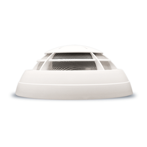
IK-E289-001GB 3.3 Anti-dusting eye protection It is obligatory to use protective anti-dusting glasses and masks during detector installation works that produce high amount of dust, such as hole drilling for detector base mounting on ceilings. 4 GENERAL DESCRIPTIONS The ADR-20N smoke detector consists of the following main parts: a base (1), a bottom (9) with an electronic circuit and a labyrinth, and a casing (6). -
Page 5: Installation
IK-E289-001GB The bottom is fixed to the casing with two screws (10). Two small devices protrude from the casing: a test button (4) and an illuminating LED (8) that indicates the detector mode. Fragments of a printed circuit board (PCB) with contact pins are visible from the bottom side. These contact pins hold connectors (3 and 11) to connect power supply (12 V DC) and a detector line through NO or NC relay contacts. - Page 6 IK-E289-001GB Fig. 3 A removal of a wire from the connector is possible after pressing down an orange blocking push-button with a finger nail. The connector with the wires should be pushed on the contact pins protruding from the detector. The detector operation should be checked by pressing the test push button and holding it for few seconds.
-
Page 7: Principles Of Operation
IK-E289-001GB An exemplary connection of the last detector into a detecting line of a burglar alarm control system – in a voltage (O) operation mode and with power supply on – is shown on Fig. 4b. 6 PRINCIPLES OF OPERATION The detector monitoring activity begins when power supply is switched on. - Page 8 8 NOTES The ADR-20R detectors do not contain any radioactive material. It should be avoided to install the detectors in draughty places. They should not be mounted above stoves, kettles and similar places where smoke or water vapour may occur.
- Page 9 IK-E289-001GB...
- Page 10 IK-E289-001GB...
Need help?
Do you have a question about the ADR-20R and is the answer not in the manual?
Questions and answers