Polon-Alfa POLON 4000 Operation And Maintenance
Interactive fire detection and alarm system, fire detection and alarm addressable control panel
Hide thumbs
Also See for POLON 4000:
- Operation and maintenance documentation (77 pages) ,
- Installation and maintenance manual (69 pages) ,
- Installation and maintenance manual (10 pages)

Subscribe to Our Youtube Channel
Related Manuals for Polon-Alfa POLON 4000


Summary of Contents for Polon-Alfa POLON 4000
- Page 1 POLON 4000 INTERACTIVE FIRE DETECTION AND ALARM SYSTEM POLON 4900 FIRE DETECTION AND ALARM ADDRESSABLE CONTROL PANEL Operation and Maintenance Documentation ID-E270-011GB IIE Edition...
- Page 2 Any nonconformity with the instructions contained in the manual may be harmful or may cause violation of the law in force POLON-ALFA bears no responsibility for any damage resulting from usage inconsistent with the manual. A waste product, unsuitable for further use, shall be passed to a waste electric and electronic equipment collection point.
-
Page 3: Table Of Contents
ID-E270-011GB CONTENTS 1. INTRODUCTION ........................6 1.1 DOCUMENTATION CONTENTS ....................... 6 1.2 CONTROL PANEL APPLICATION ..................... 6 1.3 SAFETY CONDITIONS ........................6 1.3.1 Electric shock protection ......................6 1.3.2 Installation and equipment safety ..................6 1.3.3 Repairs and maintenance ....................... 7 1.3.4 Fuse replacement ........................ - Page 4 ID-E270-011GB 7.1 DETECTION ZONE ......................... 48 7.2 ADDRESSABLE ELEMENTS DECLARATION ..................49 7.3 ASSIGNING ALARMING PARAMETERS TO ZONES ................ 49 7.4 EKS-4001 MONITORING AND CONTROLLING ELEMENTS DECLARATION ........50 7.5 EWS-4001 MULTI-OUTPUT CONTROLLING ELEMENTS DECLARATION ........55 7.6 EWK-4001 MULTI-INPUT MONITORING ELEMENTS DECLARATION ..........57 7.7 SAL-4001 ACOUSTIC SIGNALLING DEVICES DECLARATION ............
- Page 5 ID-E270-011GB 8.4.4 LK monitoring lines disablement/re-enablement ..............78 8.4.5 EKS-4001 monitoring and controlling elements disablement/re-enablement ....78 8.4.6 EWS-4001 multi-output controlling elements disablement/re-enablement ....... 78 8.4.7 EWK-4001 multi-input monitoring elements disablement/re-enablement ......78 8.4.8 SAL-4001 acoustic signalling devices disablement/re-enablement ........78 8.5 EVENT AND ALARM MEMORY .....................
-
Page 6: Introduction
It may also facilitate the process of designing fire alarm installations. The Documentation does not include other POLON 4000 system elements which are described in separate technical documents. The Manual is complemented with the Programming Manual (PM) describing the control panel programming process. -
Page 7: Repairs And Maintenance
The maintenance works and periodical inspections should be conducted by the authorised employees of companies which have been authorised or trained by Polon-Alfa personnel. All repair works must be done exclusively by the manufacturer. Polon-Alfa does not bear any responsibility for the operation of devices maintained and repaired by unauthorised personnel. - Page 8 POLON 4000 system digital monitoring (PMC-4000) A digital monitoring protocol defined in the POLON 4000 control panels. Local control panel A control panel, to which detection lines and outputs are connected, that performs signalling and operating and programming functions using its own console.
-
Page 9: Device Completeness
ID-E270-011GB Control panel local monitoring area Detection zones which are monitored by detection lines, connected to a local control panel. Control panel common monitoring area An area consisting of a control panel local monitoring area and areas of the remote control panels being declared for joint monitoring. -
Page 10: Technical Specifications
Table 2.2 Item Description Quantity Melt fuse F6,3L250 V Melt fuse F1L250 V Melt fuse F630L250 V Melt fuse F500L250 V Table 2.3 Item Description Drawing (catalogue) No. MSL-2M line module B/E270-170.00.00-1 MSI-48 mains module C/E270-70.00.00-1 PAR-4800 battery casing B/E297-00.00-1 Hanger B/E297-04.00-1 Bar code reader... - Page 11 ID-E270-011GB Maximum permissible resistance of detection line cabling - addressable line, depending on configuration 2 x 100 Ω, 2 x 75 Ω or 2 x 45 Ω - ADC-4001 side line 2 x 25 Ω - between two consecutive elements containing short circuit isolators 2 x 50 Ω...
- Page 12 - computer keyboard, - computer, - TELSAP 2100 digital monitoring system, - POLON 4000 (PMC-4000) digital monitoring system, - control panels framework interoperation – max. number of control panels - control panel co-operation with the TSR-4000 terminals – maximum number of terminals connected to one control panel...
-
Page 13: Design Descriptions
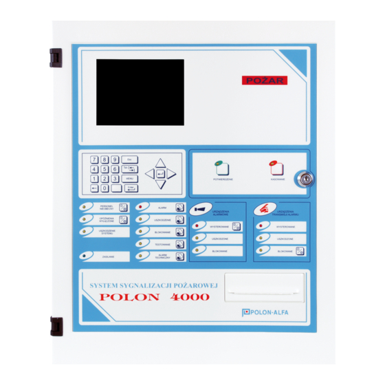
ID-E270-011GB 4 DESIGN DESCRIPTIONS 4.1 CONTROL PANEL OVERALL DESCRIPTIONS The control panel is designed in the form of a metal cuboid cabinet to be installed on walls using a special frame. The cabinet door (front panel of the unit) is secured with a cylinder lock. All signalling and handling elements are placed on the control panel door. -
Page 14: Handling And Signalling Elements
ID-E270-011GB The following modules are located on the back wall: • PPW-49 programmable outputs module, on the left upper side, • MSL-1M detection lines module, supporting 1 ÷ 4 detection lines, in the middle, • MSL-2M (optional) detection lines module, supporting 5 ÷ 8 detection lines, on the right, On the left side wall the following elements are placed: •... -
Page 15: Control Panel Handling And Signalling Elements
ID-E270-011GB 4.3.2 Control panel handling and signalling elements Fig. 4.3 Control panel handling and signalling elements 1 – ACKNOWLEDGEMENT a) indicator – active acknowledgement function, b) push button – to silence the control panel buzzer in a fire alarm, technical alarm or fault mode;... - Page 16 ID-E270-011GB a) indicator – some or all alarm device outputs are faulty. 8 – DISABLED (ALARM DEVICES) a) indicator – alarm device outputs disablement: – steady light – all alarm device outputs are disabled; – pulsing light – some alarm device outputs are disabled. 9 –...
-
Page 17: Numeric Keypad And Edition Push Buttons
ID-E270-011GB – steady light – control panel powered from the mains, no faults, – pulsing light – any power supply fault. 4.3.3 Numeric keypad and edition push buttons Fig. 4.4 Numeric keypad and edition push buttons 0 ÷ 9 – numeric keypad. MENU –... -
Page 18: Tso-4900 Operator Console
ID-E270-011GB Fig. 5.1 POLON 4900 block diagram The PSC-43 module, performing the programmed operation procedures, controls – through the bus – the relays or signalling lines on the PPW-49 module, LCD display, TSO-4900 panel signalling and handling elements. The panel purpose is to provide communication between the attending personnel and the control panel. -
Page 19: Central Controller Module
ID-E270-011GB The LCD is connected (mechanically and electrically) with the PSC-49 central controller board located on the control panel door. 5.3. PSC-49 CENTRAL CONTROLLER MODULE The central controller module is equipped with two independent microprocessor circuits (µP1 and µP2) which ensure mutual supervision and unfailing control panel operation. Each circuit has an independent set of ROM memory (in a separate MP-49 memory module), RAM operating memory and SETUP configuration memory (set of data defining the hardware environment and system operation organisation). - Page 20 ID-E270-011GB In order to carry out the operations described for the K1 or K2 key in the Table 5, it is necessary to turn the proper SW1 switch key ON, press a proper momentary switch (Reset µP1 or Reset µP2) and after about 30 seconds, turn the SW1 switch key back to the OFF position.
-
Page 21: Msl-1M, Msl-2M Line Modules
The MSL-XM line module is provided for controlling and servicing 4 detection lines to which the POLON 4000 system addressable elements are attached. Any addressable detection line can operate as a loop-shaped A type circuit or radial B type one (open line). - Page 22 ID-E270-011GB Max. current Max. resistance Jumper Line No. Jumper position [mA] [Ω] L3 (L7) 2 x 100 2 x 75 2 x 45 L4 (L8) 2 x 100 2 x 75 2 x 45 Note: In case the ADC-4001 adapter with a grounded intrinsically safe barrier on a side line is used, the earth fault signalling must be disconnected by the S4 jumper removal from the MSL-1M and MSL-2M modules.
- Page 23 ID-E270-011GB Fig. 5.3 MSL-1M line module view...
- Page 24 ID-E270-011GB Fig. 5.4 MSL-2M line module view...
-
Page 25: And Ppw-49 Programmable Outputs/Inputs Module
ID-E270-011GB 5.5 PPW-48 AND PPW-49 PROGRAMMABLE OUTPUTS/INPUTS MODULE 5.5.1 General description It is possible to install the PPW-48 module or its replacement, the PPW-49 module in the POLON 4900 control panel. The difference between those two modules consists in the possibility to monitor relay output lines by the PPW-49 module. - Page 26 ID-E270-011GB Table 5.2 Relay Condition Relay contacts status No fault, quiescent mode Closed C-NO PU (PK1) General fault Closed C-NC No actuation criterion Closed C-NC PK2÷PK16 Actuation criterion Closed C-NO Output actuation time parameters Every output: both PK relay output (except for PU) and LS potential output may operate with a defined actuation time program (also depending on the defined output time).
- Page 27 ID-E270-011GB Fig. 5.5 PPW-48 programmable outputs/inputs module...
- Page 28 ID-E270-011GB Fig. 5.6 PPW-49 programmable outputs/inputs module Specifications of the LS supervised potential output lines The potential outputs are defined as supervised outputs, i.e. they are tested by measuring the characteristic resistance of a potential line during quiescent mode in order to detect line faults with the reversed polarisation (negative) of the output voltage.
- Page 29 ID-E270-011GB control panel. After the output is actuated (according to a proper actuation variant), the output voltage polarisation is positive. Specifications of the PK supervised relay output lines The relay outputs can be supervised, in the control panel quiescent mode, in case the PPW-49 module is applied and in the control panel outputs supervision is declared.
-
Page 30: Fire Alarm Devices Outputs (Type 1)
ID-E270-011GB 5.5.3 Fire alarm devices outputs (TYPE 1) Outputs to fire alarm devices (e.g. acoustic signalling devices) may be programmed in the following variants: Table 5.4 Control Time Variant Zone Nos Activation Criterion Panel Nos Parameters stage alarm in control panel (or central panels ―... -
Page 31: Fault/Technical Alarm Signalling Output (Type 4)
ID-E270-011GB 5.5.5 Protecting devices outputs (TYPE 3) Outputs to protecting devices may be programmed in the following variants: Table 5.6 Control Zone Time Variant Panel Activation Criterion Parameters ― stage alarm in control panel ― stage alarm in control panel until acknowledgement ―... -
Page 32: Information Output (Type 5)
ID-E270-011GB EKS 1 ÷ 2 inputs non-maskable fault until ― 1 ÷ 250 acknowledgement EKS 1 ÷ 2 inputs technical alarm until ― 1 ÷ 250 acknowledgement ― ― Potential outputs fault ― ― System fault ― ― Power supply fault ―... - Page 33 ID-E270-011GB - as a technical alarm input. The input status is analysed on the basis of the monitoring line characteristic resistance measurement (Table 5.9). The range of the characteristic resistance (including the connecting cables resistance) is 2.7 kΩ - 16 kΩ. If the monitoring line resistance is outside the determined range, this condition is treated as an acknowledgement of external devices actuation (variant 1) or external devices fault (variant 2).
- Page 34 ID-E270-011GB Table 5.10 Monitored output Monitored output Variant Monitoring type type number Output inactive 1-PK, 2-LS 2 ÷ 16 or 1 ÷ 8 KZ actuation monitoring KS functioning inspection AT technical alarm Note: Outputs defined as TYPE 4 must not be assigned to monitoring lines as it may result in incorrect interpretation of the current condition if an actuation variant is assigned to a fault of monitoring or potential lines circuits.
- Page 35 ID-E270-011GB Fig. 5.9 Exemplary use of LK monitoring line assigned to LS potential output Fig. 5.10 Exemplary connection of external device contact into LK monitoring line Fig. 5.11 Exemplary use of LS potential line for acoustic signalling device actuation...
-
Page 36: Interface Module
ID-E270-011GB 5.6 MIK-48 INTERFACE MODULE The interface module is used to connect external devices to the control panel. The following elements are located on the interface panel: - one universal USB serial port connector: - ZP1 - PORT 1 - computer, PMC-4000 monitoring, TELSAP 2100 monitoring - two 9-pin EIA RS-232 standard serial port connectors: ZP2 - PORT 2 - computer, PMC-4000 monitoring, TELSAP 2100 monitoring;... -
Page 37: Port 1, Port 2, Port 3 Communication Ports
PORT TYPE: 2 - interoperation with the PMC-4000 monitoring system Used to operate with the monitoring station utilising the PMC-4000 digital monitoring protocol of the POLON 4000 system. Declared transmission bitrate: 2400 bps, 4800 bps, 9600 bps. The PMC-4000 protocol makes it possible to supply a monitoring station with information regarding... - Page 38 ID-E270-011GB - fire alarms; - technical alarms and their resets; stage alarms; - reset; - acknowledgement; - faults and their resets; - non-maskable faults and their resets; - tests and their resets; - disablements and its resets; - output actuation and its resets. Moreover, the permission for remote operation in the control panel (SYSTEM SETUP ->...
-
Page 39: Output To Tsr-4000 Terminal
ID-E270-011GB PORT TYPE: 5 - barcode reader Facilitates operation with a barcode reader to enter line elements serial numbers. 5.6.2 Output to TSR-4000 terminal The output marked as ”A”, ”B” and ”CHGND” is used only to connect the TSR-4000 terminal. It is an output of the RS485 standard serial bus to which max. - Page 40 ID-E270-011GB FIRE ALARM WITH TUN-4046 ! L-1 E-98 ZONE-25 CONFERENCE HALL 2ND FLOOR 2007-01-30 17:20:00 ** 1ST STAGE FIRE ALARM! ** 2007-01-30 17:20:00 ACKNOWLEDGEMENT ! 2007-01-30 17:22:30 ----- ALARMU RESET ----- 2007-01-30 17:25:17 The printer is equipped with a thermal paper roll (width 80 mm and max. diameter Ø...
-
Page 41: Power Supply Unit And Power Supply Module
ID-E270-011GB Fig. 5.13 DR-48 printer view from control panel inside 5.8 POWER SUPPLY UNIT AND POWER SUPPLY MODULE The POLON 4900 control panel's design makes it possible to supply it from two power sources: - AC 230 V/50 Hz - basic power source; - DC 24 V –... - Page 42 ID-E270-011GB The MZ-48 power supply module has output terminal blocks for the following voltages: - 24 V - control panel operating voltage; - 27 V - insulated voltage to supply detection lines; - 5 V - electronic circuits supply voltage; - 24 V - internal equipment supply voltage protected with a B2 /1 A fuse.
-
Page 43: Control Panel Operation With Battery Cluster
ID-E270-011GB Fig. 5.14 MZ-48 control panel power supply module 5.9 CONTROL PANEL OPERATION WITH BATTERY CLUSTER The POLON 4900 control panel may be supplied by the battery cluster comprising of two 12 V leak- proof lead-acid batteries. The battery cluster must be connected to the terminals marked as AK on the MZ-48 module board. -
Page 44: Battery Cluster Capacity Calculation
ID-E270-011GB The control panel equipped with one MSL module in standard load condition (each line consumes 20 mA), draws from the batteries the current not higher than 0.45 A. The control panel with two MSL modules can draw from the batteries the current up to 0.6 A (depending on the detection lines load). Thus, the battery charging current, equal to the difference between the maximum power supply unit current (5 A) and the sum of the current drawn by the control panel in the quiescent mode (0.6 A) and the external devices current (max. -
Page 45: Addressable Detection Lines
ID-E270-011GB min – minimum battery capacity ensuring the control panel operation for 72 h in the quiescent mode and 0.5 h in the alarm mode. Table 5.11 presents an exemplary calculation of the necessary battery cluster capacity depending on the POLON 4900 control panel hardware configuration. Table 5.11 Current draw in Current draw in... - Page 46 (i.e. fewer than a dozen or so). Fig. 6.1 POLON 4900 control panel addressable detection line examples The detection lines in the POLON 4000 system should be routed in the following manner: - radial lines without branches;...
-
Page 47: Addressable Elements Numbering
300 nF. 6.2 ADDRESSABLE ELEMENTS NUMBERING In the POLON 4000 system, each addressable element has a unique 12-digit number (factory number) but the control panel, during its normal operation, refers to addressable elements via their element numbers (short number of the 1 ÷... -
Page 48: Design Guidelines
Regardless of this, it is possible to attach the WZ-31 actuation indicators to the ADC-4001M side line detectors as well as to 4046 model range detectors. It is recommended to use screened wires in the POLON 4000 system. In the installation design process it is important to meet all requirements contained in technical specifications;... -
Page 49: Addressable Elements Declaration
ID-E270-011GB The program makes it possible to provide each zone with a text message (user message) containing two lines of text and max. 32 characters in each line. In the case an alarm is received from a zone, this text is displayed on the LCD screen showing the precise location of the fire. -
Page 50: Eks-4001 Monitoring And Controlling Elements Declaration
ID-E270-011GB Alarm variants should be matched so that they guarantee early and at the same time dependable fire danger detection. Alarm variants descriptions are contained in p. 8.1 of this OMD. As default, the control panel is programmed with the variant 2 in all zones. The alarm variants can be divided into two groups considering an alarm triggering way: 1. - Page 51 ID-E270-011GB - an element number (1 ÷ 127) using the automatic configuration or configuration with verification or manual configuration procedures; - a logical number (1 ÷ 250); - an operation mode (it is set by default but may be changed – see below). The EKS-4001 operation mode is defined by the following element parameters (standard mode in bold print): - output line continuity monitoring (YES or NO);...
- Page 52 ID-E270-011GB Table 7.1 Control Zones/EKS/EWK Variant Panel Actuation Criterion Numbers ― ― inactive output ― stage general alarm 0 ÷ 31 0 ÷ 1024 ‘union’ of 1 stage alarms in assigned zones 0 ÷ 31 0 ÷ 1024 ‘conjunction’ of 1 stage alarms in assigned zones ―...
- Page 53 ID-E270-011GB Variant 0 - No EKS actuation criterion (output permanently deactivated). Variant 1 – general 1 stage alarm - The output is activated in case a 1 stage alarm is generated in the control panel or in any control panel from the common detection area. Variant 2 –...
- Page 54 ID-E270-011GB - the output is activated in case a non-maskable fault is revealed in at least one assigned input from the list of assigned EKS elements. The assigned inputs may not include own inputs of the controlled EKS element. The list of assigned EKS inputs may include only their own control panel (when the control panel operates in a network).
-
Page 55: Ews-4001 Multi-Output Controlling Elements Declaration
0 which makes them inactive. An illustration of an exemplary implementation of an EKS-4001 element is provided in the manual called "Designing fire alarm installations using the POLON 4000 interactive fire signalling system" and the EKS-4001 Installation and Maintenance Manual. - Page 56 ID-E270-011GB Table 7.2 Control Zones Variant Panel Actuation Criterion Numbers ― ― inactive output ― general 1 stage alarm 0 ÷ 31 0 ÷ 1024 ‘conjunction’ of 1 stage alarms in assigned zones 0 ÷ 31 0 ÷ 1024 ‘conjunction’ of 1 stage alarms in assigned zones ―...
-
Page 57: Ewk-4001 Multi-Input Monitoring Elements Declaration
ID-E270-011GB The output activation is performed in the case of a 2 stage alarm occurrence in at least two zones that are assigned to this relay. Variant 7 – reset output The reset output is provided in order to generate a resetting impulse, lasting for ca. 1.5 s, after fire alarm reset. -
Page 58: Sal-4001 Acoustic Signalling Devices Declaration
ID-E270-011GB The EWK-4001 entire programming procedure includes two stages: Stage I: EWK-4001 declaration consisting in assigning: - an element number (1 ÷ 127) using the automatic configuration or the configuration with verification or the manual configuration procedures; - a logical number (1 ÷ 100); - an operation mode (it is factory set but may be changed - see below). - Page 59 ID-E270-011GB The SAL proper programming consists in declaring a line element (similarly to fire warning devices), assigning it to a logical number and assigning the type and actuation variant by means of this logical number. A logical number for the SAL element is selected from the 1 ÷ 250 range and assigned to an element in order to make the SAL actuation variants dependent on different events in the control panel.
- Page 60 ID-E270-011GB Type1 Table 7.3 Control Zones Time Variant Panels Actuation Criterion Numbers Parameters stage alarm in control panel (or control panel group ― in case of network operation) or activation with ACTIVATION push button in ALARM DEVICES area 0 ÷ 31 0 ÷...
-
Page 61: Ucs 4000 Universal Controlling Panels Declaration
ID-E270-011GB The type and actuation variants are programmed only for a SAL element with a logical number defined. As far as the variants with zone dependence are concerned, the assigned zones may originate in their own control panel (a standalone control panel) or in any control panels from the common detection area (a control panel operating in a network). - Page 62 ID-E270-011GB conventional detection line fault (PSU-4000 module); RPO (manual smoke exhaust button) line fault (PSU-4000 module); fault of an output to alarm devices (PSU-4000 module); power supply (fuse) of a rain/wind sensor fault (PSU-4000 module); declared PSD-4000 module faulty or lack;...
- Page 63 ID-E270-011GB - modes of an addressable module for communication with the POLON 4000 system: o EEPROM memory fault; o short circuit isolator actuation; o shot circuit isolation; o no connection between the line processor and main UCS element. Depending on whether the programmed variant condition is met, the POLON 4900 control panel may send a signal actuating the P1 main relay to the UCS (and other outputs individually dependent on this signal).
- Page 64 ID-E270-011GB Table 7.5 Control Zone Variant Panel Actuation criterion Number ― ― Inactive output ― stage general alarm 0 ÷ 31 0 ÷ 1024 ‘union’ of 1 stage alarms in assigned zones 0 ÷ 31 0 ÷ 1024 ‘conjunction’ of 1 stage alarms in assigned zones ―...
-
Page 65: Ucs 6000 Universal Control Panels Declaration
ID-E270-011GB The P1 main relay actuation variants are programmed only for a UCS unit with a logical number defined. In case variant 2 or 5 is used, at least one zone must be assigned to the UCS, however, if variant 3 or 6 is used, at least two zones must be assigned. - Page 66 ID-E270-011GB - a logical number (1 ÷ 100); Stage II: UCS 6000 logical configuration consisting in: - declaring MGL modules; - declaring an MPD module; - declaring MPW modules; - defining the zone for the fire alarm generated by the MGS module; - MGL modules configuration: •...
- Page 67 ID-E270-011GB 0 ÷ 31 0 ÷ 1024 ‘conjunction’ of 1 stage alarms in assigned zones ― general 2 stage alarm 0 ÷ 31 0 ÷ 1024 ‘union’ of 2 stage alarms in assigned zones 0 ÷ 31 0 ÷ 1024 ‘conjunction’ of 2 stage alarms in assigned zones Variant 0 Means lack of an actuation criterion (permanently non-activated output).
-
Page 68: Tsr-4000 Terminal Declaration
0, which causes that such an element is inactive. 7.10 TSR-4000 TERMINAL DECLARATION A TSR-4000 terminal is a remote device to signal the POLON 4000 system control panel modes. Up to 16 terminals may be connected to one control panel and an RS-485 serial interface is responsible for transmission. -
Page 69: One-Stage Alarm (Variant #1)
ID-E270-011GB apart from the first one which is permanently displayed in two alarm window lines and the last one displayed in the last two lines. stage alarm is an internal control panel mode (indicated by internal acoustic signalling and the STAGE ALARM message in the location of the previously displayed monitoring clock) which, apart from generating the signals in the control panel, causes the transmission of the fire signal outside (actuation of declared outputs as outputs to alarming-monitoring devices and actuation of additional... -
Page 70: One-Stage Alarm With Single Reset (60 Sec./8 Min.) Of A Fire Warning Device (Variant #4)
ID-E270-011GB signals from the facility. If, during 60 seconds, the same or different fire warning device is not actuated in the same zone again, the control panel generates a 2 stage alarm. If the same or different element in the same zone is not re-actuated during 60 seconds, the control panel will treat the previous actuation as a false alarm. -
Page 71: Two-Stage Alarm With A Coincidence Including Two Fire Warning Devices (Variant #8)
ID-E270-011GB 8.1.9 Two-stage alarm with a coincidence including two fire warning devices (variant #8) After a fire warning device is actuated, it is initially reset and the control panel generates the initial alarm mode. If, during 8 minutes, the reset device and at least one more device in the same zone are actuated, the control panel generates a 1 stage alarm and the alarming process is the same as in variant 2. -
Page 72: Two-Stage Alarm With A Group-Time Coincidence To Accelerate A 2 #13)
ID-E270-011GB report actuation, the control panel generates a 1 stage alarm and the alarming procedure is the same as in variant 2. Otherwise, after 8 minutes, the control panel resets the preliminary alarm mode treating the devices actuation as false and returns to the quiescent mode. Note: Correct operation of this variant requires that one (preferably two) fire warning device is declared both for group A and group B. -
Page 73: Two-Stage Alarm With Initial Zone Reset And A Coincidence Including Two Fire Warning
ID-E270-011GB 8.1.17 Two-stage alarm with initial zone RESET and a coincidence including two fire warning devices to accelerate a 2 stage alarm (variant #16) After a fire warning device belonging to a zone is actuated, the control panel waits for 40 seconds and resets the zone automatically. -
Page 74: Faults Signalling
ID-E270-011GB The operation mode is switched after pressing the PERSONNEL ABSENT push button (the diode located in this push button is lit). Changing the control panel operation mode is possible with at least access level. The operation mode is automatically switched to PERSONNEL ABSENT when one of the four times for automatic operation mode switching into the PERSONNEL ABSENT is programmed. - Page 75 ID-E270-011GB - detection line earth fault; - number of line elements in a detection loop exceeding 127; - presence of not declared elements in a detection line; - incorrect parameters for the detection loop (resistance, capacity); - no response from a line element to a query from the control panel; - multiple declaration of the same line element.
-
Page 76: Testing
ID-E270-011GB - voltage drop below 22 V; - terminal earth fault. 9. Other faults: - thermal printer fault; - no paper in the printer - UCS 4000 control panel faults ( opisane w rozdziale poświęconym temu urządzeniu). Note: In order to reset a system fault, it is necessary to switch the K6 key of the SW1 switch on the PSC board and reset the active microprocessor. -
Page 77: Eks-4001 Monitoring And Controlling Elements Testing
ID-E270-011GB It is impossible to switch the system into the TEST mode within faulty or disabled zones or in case a fire alarm is signalled. 8.3.3 EKS-4001 monitoring and controlling elements testing The EKS-4001 monitoring and controlling elements tests consist in switching an element into the testing mode, which should result in actuating an output relay. -
Page 78: Pk Relays Disablement/Re-Enablement
ID-E270-011GB A partial zone disablement, with programmed alarm variant higher than the second one, causes that this zone variant is automatically replaced with the immediate one (variant 1). After the zone complete re-enablement, the initially programmed variant recurs. 8.4.2 PK relays disablement/re-enablement The PK relays disablement/re-enablement is accomplished in the RELAYS DISABLEMENT option. -
Page 79: Alarm Memory
9 CONTROL PANEL NETWORK OPERATION The POLON 4000 system control panels may be connected with one another by means of a double pair of wires (or a pair of optical fibre cables) in a form of a ring in order to create a network of control panels. -
Page 80: Network Module
ID-E270-011GB to collect fire and fault signals from several control panels without reciprocity or with full reciprocity. The network logical configuration diagram is shown in Fig. 9.1. In special cases, the collective control panel may serve as a local control panel if no remote panel has been declared to co-operate with it. - Page 81 ID-E270-011GB The MSI-48 module is equipped with an 8-position switch containing keys K1...K8. Keys K1...K5 are used to assign (by means of hardware) a number to a control panel using the binary code. Each of these five keys has significance (Wn) defined by its number. The control panel number may be expressed by means of the following formula: CONTROL PANEL NO.
- Page 82 ID-E270-011GB - TR-43.7.2 for 9/125 μm single-mode fibre-optic cables (1,300 nm wave) terminated with the FC type contacts. This type connection enables reaching the distance between two neighbouring control panels in a ring equal to approx. 12 km (depending on the cables attenuation).
- Page 83 ID-E270-011GB Every converter is equipped with a special latch for fast installation on a typical supporting rail (DIN EN 50022) located below the control panel top wall. The converters should be power supplied with + 24 V voltage which can be routed from the MZ-48 module or MIK-48 module output terminal blocks. If the converters are powered from the control panel voltage and the MSI-48 Ed.3 module, the ZW7 jumper should be switched into the 2-3 position.
- Page 84 ID-E270-011GB influence the transmission continuity between the control panels). It is advisable that the power supply device is fitted with a latch (similarly to the optical fibre converter) to enable its installation on the rail shared with the converters. Fig. 9.4 Four control panels network connection with a pair of optical fibres (ST type contact)
- Page 85 ID-E270-011GB Fig. 9.5 Four control panels network connection with a pair of optical fibres (SC/PC type contact)
-
Page 86: Network Panel Functionality
ID-E270-011GB 9.2 NETWORK PANEL FUNCTIONALITY The console of a control panel operating in the network may work in three display and access modes: - local mode – when a control panel with a local number is selected; - collective (group) mode – when a control panel with number 0 is selected; - remote mode –... -
Page 87: Remote Mode
ID-E270-011GB - TEST indicator – global testing mode for the control panels of the common detection area; the push button enables display of all control panel tests and general information regarding the test occurrences in the control panels within the common detection area. In order to view the fault tests within the remote control panel in detail, select the remote control panel and view its tests. - Page 88 ID-E270-011GB Note: Common detection areas should be created as follows: - Hierarchical group: among n allocated control panels only one k control panel (collective control panel) has the remaining n-1 control panels declared to the common detection area. The general diagram of a hierarchical group is as follows: C1→Ck, C2→Ck, ..
-
Page 89: Standard Configuration
ID-E270-011GB 10 STANDARD CONFIGURATION The POLON 4900 control panel delivered to a customer has manufacturer's pre-programmed operation modes defined as the standard configuration. According to the standard configuration, a control panel is programmed as follows: - the MSL-1M module is declared by default (all loop-shaped lines); MSL-2M and MSI-48 modules are not declared;... -
Page 90: User Configuration Programming
ID-E270-011GB 10.1 USER CONFIGURATION PROGRAMMING In order to adjust the control panel to its operation conditions predicted in the circuit design, it is necessary to program the panel individually. The panel must be programmed according to the programming manual (PM) after obtaining the 3 or 4 access level authorisation. -
Page 91: Installation
ID-E270-011GB Access level Operator access Allowable operations **** level access As per 3 level plus hardware configuration change code for the control panel direct servicing personnel ** for the direct servicing personnel or the maintenance technician *** for a person being authorised for program configuration change **** for the manufacturer and authorised servicing company for hardware configuration change. -
Page 92: Power Supply Connection
ID-E270-011GB Ambient temperature should not be lower than 0 °C and higher than + 40 °C. In the case of high noise level, outdoor acoustic signalling devices should be applicable, controlled by signalling line or the relay contacts. The control panel should be fixed to a wall using a special supporting frame delivered with the device. -
Page 93: Line Elements Installation
ID-E270-011GB 12.3 LINE ELEMENTS INSTALLATION Detection line wires and external signalling circuits wires are introduced to the control panel through a round opening in the back side of the panel. Before wire connection, it is necessary to examine thoroughly particular circuits routing to the control panel output switch clamps. -
Page 94: Control Panel Inputs And Outputs
ID-E270-011GB 12.4 CONTROL PANEL INPUTS AND OUTPUTS Terminal Contacts marking Location Description block – + P1 MSL-1M Detection loop 1 return – + L1 „ Detection line/loop 1 output – + P2 „ Detection loop 2 return – + L2 „... - Page 95 ID-E270-011GB closed C–NO 2 C–NC–NO „ Relay No. 2 programmable outputs 3 C–NC–NO „ Relay No. 3 programmable outputs 4 C–NC–NO „ Relay No. 4 programmable outputs 5 C–NC–NO „ Relay No. 5 programmable outputs 6 C–NC–NO „ Relay No. 6 programmable outputs 7 C–NC–NO „...
- Page 96 ID-E270-011GB 4 + – „ Signalling line output (of 0.1 A load in alarm) 5 + – „ Signalling line output (of 0.1 A load in alarm) 6 + – „ Signalling line output (of 0.1 A load in alarm) 7 + –...
-
Page 97: Operation And Maintenance
ID-E270-011GB A B, CHGND „ TSR 4000 terminal output WE-1 A , B MSI-48 Control panel network ring 1 input WY-1 A , B „ Control panel network ring 1 output WY-2 A , B „ Control panel network ring 2 output WE-2 A , B „... -
Page 98: Packing, Transportation, Storage
ID-E270-011GB Every 6 months it recommended to check connections between the control panel case and the shielding, grounding and zeroing cable and to clean battery clamps. The battery charging level should be checked at least once a year. For this purpose, it is necessary to disconnect the mains power supply with the AC power supply switch for approx. -
Page 99: Designer's Tables
ID-E270-011GB 15 DESIGNER'S TABLES Table 15.1 MSL MODULES DECLARATION LINE No. 1 : ....MSL- 1 module LINE No. 2 : ............. LINE No. 3 : ....LINE No. 4 : ....LINE No. 5 : ....LINE No. 6 : ....MSL- 2 module LINE No. - Page 100 ID-E270-011GB Table 15.6 ZONES CONFIGURATION Zone No. Alarming variant Message max 32 characters (text line 1) Message max 32 characters (text line 2) Table 16.7 EKS – 4001 MONITORING AND CONTROLLING ELEMENTS PARAMETERS Operation mode Continuity Output Line Elem. Actuation Monitoring logical Factory No.
- Page 101 ID-E270-011GB Table 15.8 EKS – 4001 MONITORING AND CONTROLLING ELEMENTS LOGICAL CONFIGURATION User message Actuation Input logical Assigned zones Variant Non-maskable fault Technical alarm max 32 characters max 32 characters max 32 characters max 32 characters...
- Page 102 ID-E270-011GB Table 15.9 RELAYS CONFIGURATION PK Number Zones/EKS Type Variant Delay Table 15.10 SIGNALLING LINES CONFIGURATION LS Number Type Zones/EKS Variant Delay...
- Page 103 ID-E270-011GB Table 15.11 MONITORING LINES CONFIGURATION User message Monitored Monitored Variant output type output No. PK/LS (only in var.1) Non-maskable fault Technical alarm max 2x32 characters max 2x32 characters ..........................................................................................
- Page 104 ID-E270-011GB Table 15.13 EWK-4001 MULTI-INPUT MONITORING ELEMENTS PARAMETERS AND CONFIGURATION Line Elem. EWK log. Input Input monitoring Technical alarm Factory No. variant message Table 15.14 SAL – 4001 ACOUSTIC SIGNALLING DEVICES PARAMETERS AND CONFIGURATION Line Elem. Oper. SAL log. Output Actuation Factory No.
- Page 105 UCS 4000 universal fire control panel 600 µA UCS 6000 universal fire control panel 600 µA maximum current drawn by element from detection line/loop of POLON 4000 system control panel. signalling device without additional power supply must be provided with line/loop current for alarming.
Need help?
Do you have a question about the POLON 4000 and is the answer not in the manual?
Questions and answers