
Subscribe to Our Youtube Channel
Related Manuals for Polon-Alfa DOT?4046


Summary of Contents for Polon-Alfa DOT?4046
- Page 1 POLON 4000 INTERACTIVE FIRE DETECTION AND ALARM SYSTEM DOT‐4046 MULTI‐SENSOR SMOKE AND HEAT DETECTOR Installation and Maintenance Manual IK‐E301‐001GB IIIB Edition ...
- Page 2 2 IK‐E301‐001GB The DOT‐4046 multi‐sensor smoke and heat detector covered by the present manual complies with the requirements of the following European Union Directives: CPD 89/106/EWG on construction materials; EMC 2004/108/WE on electromagnetic compatibility. The DOT‐4046 multi‐sensor smoke and heat detector has been approved with the EC‐Certificate of Conformity No. 1438/CPD/0015 issued by the Scientific and Research Centre for Fire Protection (CNBOP) Józefów, Poland, an EU notified authority No. 1438, confirming its compliance with the requirements of PN‐EN 54‐5:2003 and PN‐EN 54‐7:2004 standards. ...
- Page 3 IK‐E301‐001GB 3 1 PURPOSE The DOT‐4046 multi‐sensor addressable smoke and heat detector is designed for detection of a fire temperature rise may be observed. initial phase when a smoke occurs and/or The detector is characterised by a high resistance level against wind movement and pressure change. The DOT‐4046 multi‐sensor addressable detectors are intended to operate in the POLON 4000 fire detecting and alarm system control panel addressable lines. They are equipped with internal short circuit isolators. 2 TECHNICAL SPECIFICATIONS Operating voltage 16.5 V ÷ 24.6 V Maximum current draw ≤ 150 µA Maximum installation height *) 7.5 m Maximum supervised area *) 40 m Operating temperature: ‐ for ‘1’ and ‘2’ modes ...
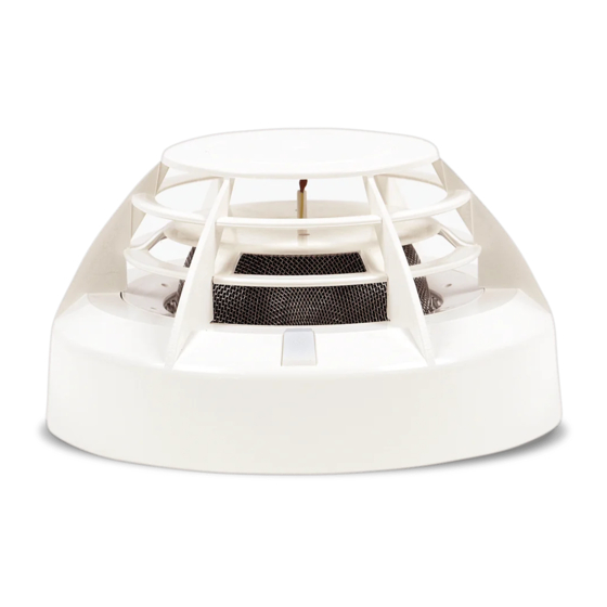
- Page 4 4 IK‐E301‐001GB Any electric tools shall be used strictly obeying the safety rules stated in instruction manuals by manufacturers. 3.3 Anti‐dusting eye protection It is obligatory to use protective anti‐dusting glasses and masks during detector installation works that produce high amount of dust, such as hole drilling in ceilings. 4 DESIGN DESCRIPTIONS The DOT‐4046 detector is equipped with two sensors that detect two fire factors: heat and smoke. Heat is detected by a temperature‐sensitive resistor (thermistor) whereas smoke is detected by a special optical module consisting of a light transmitting diode and a receiving one. They are mounted ...
- Page 5 IK‐E301‐001GB 5 6 DETECTOR OPERATION MODES Detector is furnished with four basic operation modes (apart from alarm variants in the control panel) that enable the best adjustment of its characteristics to given operation environment: ‐ ‘1’ mode ‐ multi‐criteria, equivalent to interoperation of two smoke detectors (DOP) and two heat detectors (TUP) in A1R class; ‐ ‘2’ mode ‐ multi‐criteria, equivalent to interoperation of a smoke detector (DOP) and a heat detector (TUP) in BR class; ‐ ‘3’ mode ‐ independent, equivalent to independent operation of two detectors, providing the same suitability as DOR detector and TUP detector in A1R class. ...
- Page 6 6 IK‐E301‐001GB the detector triggers a technical alarm mode sending excessive contamination information to the control panel. The panel signals a necessity to clean the detector optical module: the labyrinth and lenses of both diodes – the transmitting one and photodiode. Servicing activities should be taken up as soon as possible to avoid false alarm evoking. Fig. 1 Detector elements after dismantling The detector assembling and dismantling is shown on Fig. 1. In order to dismantle the detector it is necessary to: a) pressing the net long tongue, turn the cover right in the basket until it is taken out; b) remove and bend aside the thermistor basis from the labyrinth; c) unfasten two screws that fix the labyrinth and take the labyrinth out; d) perform the necessary cleaning. A delicate brush as well as vacuum cleaner are recommended for cleaning works. Compressed air can be possibly used. It is permitted to wash the labyrinth with warm water with addition of washing‐up liquid. No damp patches should remain on the labyrinth internal surfaces after washing and drying. ...
- Page 7 IK‐E301‐001GB 7 After cleaning the detector should be assembled. In order to do it, it is necessary to: a) fasten the labyrinth with two screws; b) locate thermistor basis placing the thermistor leads into the labyrinth notches; c) lay down the basket in the position as shown on the figure; d) insert the masking grid into the basket paying attention to its positioning – alignment with the juts; e) insert the net into the basket paying attention to positioning – alignment with the juts; f) insert the cover into the basket so that the activation indicator diode is placed a little to the right in relation to the glass; g) turn the cover to the left. Note: In case the cleaning does not produce the required result, it is necessary to send the detector to the manufacturer for repair. 7 DETECTOR INSTALLATION The DOT‐4046 detectors are installed (height, arrangement) according to the guidelines settled by the Scientific and Research Centre for Fire Protection. They are mounted in premises where a smoke ...
- Page 8 8 IK‐E301‐001GB Fig. 2 Clamps of base interoperating with DOT‐4046 plug IK‐E301‐001GB/05.2011/01.2012 ...
Need help?
Do you have a question about the DOT?4046 and is the answer not in the manual?
Questions and answers