
Related Manuals for Polon-Alfa DOR-4046


Summary of Contents for Polon-Alfa DOR-4046
- Page 1 POLON 4000 INTERACTIVE FIRE DETECTION AND ALARM SYSTEM DOR‐4046 ADDRESSABLE MULTI‐STATE OPTICAL SMOKE DETECTOR Installation and Maintenance Manual IK‐E282‐001GB IIIA Edition ...
- Page 2 2 IP‐E282‐001GB The DOR‐4046 addressable optical smoke detector covered by this manual, complies with the requirements of the following European Union directives: CPD 89/106/EWG ‐ on construction materials; EMC 2004/108/WE ‐ on electromagnetic compatibility. The DOR‐4046 addressable optical smoke detector has been approved with the EC Certificate of Conformity ...
- Page 3 3 IP‐E282‐001GB 1 PURPOSE The DOR‐4046 microprocessor based, interactive optical smoke detector is designed for detection of visible smoke that is concurrent with most fire combustion. It enables a fire detection at a start of its flameless stage when material starts to smoulder, and therefore generally, a long time prior to the appearance of an open flame and a noticeable rise in temperature. The detector is characterised by a ...
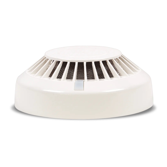
- Page 4 4 IP‐E282‐001GB 3.3 Anti‐dusting eye protection It is obligatory to use protective anti‐dusting glasses and masks during detector installation works that produce high amount of dust, such as hole drilling for detector base mounting on ceilings. 4 CONSTRUCTION DESCRIPTIONS The detector mechanical construction is shown in Fig. 1. Its basic element is a detection optical module consisting of transmitting infrared diode and a photodiode acting as a receiver. They are mounted in a holder in such a way that radiation emitted by the transmitting diode does not reach the other diode directly. The detecting module (holder with diodes) is fastened to a printed board that contains all electronic ...
- Page 5 5 IP‐E282‐001GB Communication between the POLON 4000 fire alarm control panel and the DOR‐4046 detectors is obtained with an addressable two‐wire detection line. Unique, fully digital communication protocol enables passing any information from the fire alarm control panel to the detector and inversely. Apart from transmitting an evaluation of fire factors and tendency of their changes, the detector passes to the control panel, on its request, the current analogue value. The detector operation controlling microprocessor monitors correctness of its basic circuits operation and, in case an irregularity is found, reports relevant information to the control panel. ...
- Page 6 6 IP‐E282‐001GB progress, the detector triggers the technical alarm mode sending excessive contamination information to the control panel. It causes a necessity to clean the detector optical module: the labyrinth and the lenses of both diodes – transmitting one and photodiode. A failure to carry out the servicing works may result in false alarm evoking in future. Fig.2 Detector elements after dismantling The detector assembling and dismantling is shown in Fig. 2. In order to dismantle the detector it is necessary to: a) pressing the net long tongue, turn the cover right in the basket until it is taken out; ...
- Page 7 7 IP‐E282‐001GB b) remove two screws that fix the labyrinth and take the labyrinth out; c) perform the necessary cleaning. A delicate brush as well as vacuum cleaner are recommended for cleaning. Compressed air can be possibly used. It is permitted to wash the labyrinth with warm water with addition of washing‐up liquid. No damp patches should remain on the labyrinth internal surfaces after washing and drying. After cleaning the detector should be assembled, its functioning should be tested using a smoke imitator or smoke generator and installed again into the detection line. In this order to assemble the detector, it is necessary to: a) fasten the labyrinth with two screws; b) place the basket in the reverse position as that shown in the figure; c) insert the net into the basket paying attention to its positioning – alignment with the juts; d) insert the cover into the basket so that the illuminating diode is placed a little to the right in relation to the glass; ...
- Page 8 8 IP‐E282‐001GB The detectors shall not be exposed to direct sunlight or heat emitted by heaters. The storage period of the detectors in transport package should not exceed 6 months. 8.2 Transportation The DOR‐4046 detectors should be carried in closed spaces of transport means in proper packing that meet appropriate transport regulations. Transport temperature shall not be lower than ‐ 40 °C and higher than + 70 °C; relative humidity shall not exceed 95% at + 45 °C or 80 % at + 70 °C. Fig. 3 Clamps of base interoperating with DOR‐4046 plug ...
Need help?
Do you have a question about the DOR-4046 and is the answer not in the manual?
Questions and answers