
Subscribe to Our Youtube Channel
Related Manuals for Polon-Alfa ADR-20N


Summary of Contents for Polon-Alfa ADR-20N
- Page 1 ADR‐20N SELF‐CONTAINED OPTICAL SMOKE DETECTOR Installation and Maintenance Manual IK‐E289‐003GB Issue 1A ...
- Page 2 IK-E322-001GB _____________________________________________________________________________ The ADR‐20N residential self‐contained optical smoke detector covered by this manual, complies with the requirements of the following European Union directives: CPD 89/106/EWG ‐ on construction materials; EMC 2004/108/WE ‐ on electromagnetic compatibility. The ADR‐20N optical smoke detector has been approved with the EC Certificate of Conformity No. 1438/CPD/0145, issued by the Scientific and Research Centre for Fire Protection (CNBOP) Józefów, Poland, ...
- Page 3 IK-E322-001GB _____________________________________________________________________________ 1 PURPOSE The ADR‐20N optical smoke detector is designed for detection of a visible smoke that is concurrent with most fire combustion. It is dedicated to monitor residential facilities, cellars, garages, attics, etc. The detector is battery‐operated using a replaceable 9V 6F22 battery mounted inside its casing. It is possible to inter‐connect detectors with a two‐core cable creating a detecting network – detection of a fire by one detector activates an alarm signal in other detectors in the supervised premises. 2 TECHNICAL SPECIFICATIONS Power supply 9 V 6F22 battery (not included) Quiescent current < 10 µA Operation temperature range from ‐10 C to +55 C Relative humidity ≤ 95 % at 40 C Detector mass (without battery) ≤ 0.13 kg Dimensions (with base) Ø112 x 57 mm Sensitivity to test aerosol ...
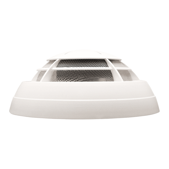
- Page 4 IK-E322-001GB _____________________________________________________________________________ are installed inside the bottom. The casing encloses a wire grid that prevents irruption of small insects or pieces of dirt. Fig. 1 The bottom is fixed to the casing with two screws (10). Two small devices protrude from the casing: a test button (4) and an illuminating LED (8) that indicates the detector mode. Fragments of a printed ...
- Page 5 IK-E322-001GB _____________________________________________________________________________ circuit board (PCB) with contact pins are visible from the bottom side. These contact pins hold a connector (11) to interconnect several detectors in a network. 5 INSTALLATION The detectors are recommended to be installed in all rooms exposed to a high fire hazard level. They may be mounted in hallways, staircases as well as in passages between rooms endangered by a fire occurrence. ...
- Page 6 IK-E322-001GB _____________________________________________________________________________ Fig. 3 6 PRINCIPLES OF OPERATION The detector monitoring activity begins when a battery power supply is connected. An information about the detector mode is communicated by acoustic and optical signals as per the following table: Short audio Modulated LED LED flashing Detector mode signal audio signal flashing 40 s interval 40 s interval Supervision, x smoke detection Alarm ...
- Page 7 IK-E322-001GB _____________________________________________________________________________ 7 MAINTENANCE INSTRUCTIONS In case of dust accumulation inside the measuring chamber, which may be a result of a long‐term device, the detector sensitivity level will increase up to evoking false alarms. It is recommended to clean the optical module (i.e. the labyrinth and lenses of both transmitting diode and receiving photodiode which are placed within the labyrinth) every year. In order to carry the cleaning process out, it is necessary: − remove the detector from its base turning it counter clockwise and taking it off; − disconnect the connector (11); − remove two screws (10) fastening the bottom (9) to the casing (6) of the detector; − take the casing off; − bend softly the catches that hold the labyrinth (5) and take it out; − using soft brush clean carefully the labyrinth, the hollows where the diodes are placed as well as the metal cover from the side of the labyrinth; − in case such cleaning is not effective, it is allowed to wash the labyrinth with warm water with ...
Need help?
Do you have a question about the ADR-20N and is the answer not in the manual?
Questions and answers