
Related Manuals for MAHA CARLIFT 4.1


Summary of Contents for MAHA CARLIFT 4.1
- Page 1 Four Post Lift CARLIFT 4.1 for vehicles up to 4,000 kg gross weight Technical Handbook English D1 3610TH1-GB02...
- Page 2 The contents of this edition have been checked with great care. However, errors cannot be fully excluded. Please contact MAHA should you find errors of any kind. These instructions are intended for users with previous knowledge in the field of automotive vehicle service lifts.
-
Page 3: Table Of Contents
CARLIFT 4.1 ONTENTS Description ........................ 1 Options and Accessories ....................... 1 1.1.1 Standard Lift ........................1 1.1.2 Wheel Alignment Lift....................... 1 1.1.3 Test Lane Lift........................1 Specifications..........................2 Noise Emission ..........................4 Installation Requirements ......................4 1.4.1 Location .......................... 4 1.4.2... - Page 4 CARLIFT 4.1 D1 3610TH1-GB02...
-
Page 5: Description
CARLIFT 4.1 Description Options and Accessories 1.1.1 Standard Lift Š Runway extension (4800 mm) Š Exit ramps Š Runway lighting Š Shockproof socket 230 V, 16 A Š Ceiling light barrier Š Granulate coating for runways Š Compressed-air conditioner including pressure regulator, oiler, water trap, manometer, automatic drain Š... -
Page 6: Specifications
CARLIFT 4.1 Description Specifications D1 3610TH1-GB02... - Page 7 Description CARLIFT 4.1 Runway length 4400 mm 4800 mm Dead weight 2700 kg 2900 kg Rated load capacity 4000 kg Column height HS 2440 mm Lifting rise max. HO 1900 mm Lifting rise min. HU 170 mm / 220 mm...
-
Page 8: Noise Emission
Foundation Prior to installation a sufficiently stable foundation and level lift bay floor shall be completed in accordance with MAHA recommendations. Minimum concrete thickness: 200 mm reinforced. Always use the latest foundation plans available from MAHA. Proof of safe floor load capacity is the owner's responsibility. -
Page 9: Installation
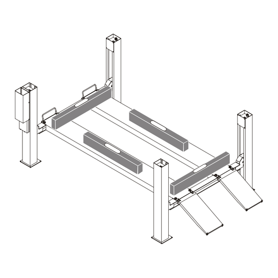
CARLIFT 4.1 Installation Four (4) stands and a hoist or forklift are required for lift installation. Cross Supports Assemble the lift on its final location. For lift positioning and dimensions see also sections "Specifications" and "Appendix B". Drawing not true to scale. -
Page 10: Runways
CARLIFT 4.1 Installation Runways Approach Column with power and control unit Position the runways on the cross supports. Q1 Front cross support with cable tube The runway with the hydraulic cylinder must be Q2 Back cross support placed between columns 1 and 4. -
Page 11: Fasteners
Installation CARLIFT 4.1 Fasteners Check to be sure the cross supports are at right angles with the runways. Wheel alignment lifts: Fasten both runways to the cross supports. Use the fastening screws (B) to adjust the cross supports. For fine adjustment of the runways use the levelling screws (NF). -
Page 12: Lifting Cables
CARLIFT 4.1 Installation Lifting Cables Run the lifting cables around the sheaves as shown above. Cable 1 column 1 etc. D1 3610TH1-GB02... -
Page 13: Length Of Cables
Installation CARLIFT 4.1 2.4.1 Length of Cables Runway Length 4.40 m 4.80 m Cable 1 Left Front Column 8.06 m 8.34 m Cable 2 Right Front Column 9.63 m 9.91 m 5LJKW %DFN &ROXPQ Cable 3 4.70 m 4.57 m /HIW %DFN &ROXPQ... -
Page 14: Columns
CARLIFT 4.1 Installation Columns Position the columns close to the carriages. Be sure to install column 1 (including power and control unit) at the left front position. The other columns are identical and may be positioned in any order. Insert the lock ladder through the slot on top of the column and through the carriage. -
Page 15: Anchoring
Installation CARLIFT 4.1 Anchoring 16 anchors, model UPAT EXA 10/90, are standard supplied. Longer anchors are available on request. Follow the anchor manufacturer's installation instructions. 2.6.1 Anchor Dimensions Min. hole depth w/o fixture, tiles Max. thickness of Min. embedment Drill bit ∅... -
Page 16: Anchor Installation
CARLIFT 4.1 Installation 2.6.2 Anchor Installation Drill a hole as Blow the hole clean of Drive the anchor Tighten the nut using recommended by the dust and other through the fixture into a torque wrench. anchor manufacturer. material. the anchor hole until the nut is firmly seated against the fixture. -
Page 17: Hydraulic Installation
Installation CARLIFT 4.1 Hydraulic Installation 1 Solenoid valve with manual lowering screw 2 Manometer connection 3 Hydraulic connection 4 Overflow oil line connection 5 Filler cap 6 Pressure adjusting screw Before initial operation replace the provisional filler cap by a fill-breather cap. -
Page 18: Bleeding
CARLIFT 4.1 Installation Bleeding Do not bleed the hydraulic system with the lift loaded. The bleeder screw is accessible through a hole in one of the runways. Use an Allen key with a minimum length of 80 mm. Runways will lower during bleeding procedure. -
Page 19: Levelling Of Runways For Standard Lifts
Installation CARLIFT 4.1 2.10 Levelling of Runways for Standard Lifts 2.10.1 Adjustment of Cable Length Š Raise the loaded lift to approx. midpoint of travel. Š Open the lock nuts of all lifting cables. Š Level the runways (see illustration above) by adjusting the fastening nuts as required. -
Page 20: Levelling And Adjustment Of Wheel Alignment Lifts
CARLIFT 4.1 Installation 2.11 Levelling and Adjustment of Wheel Alignment Lifts 2.11.1 Levelling of Cross Supports in Wheel Alignment Position Š Raise the lift to wheel alignment height and set the runways on the locks. Š Open the lock nuts (2) of all lock ladders (4). -
Page 21: Levelling Of Cross Supports In Fully Lowered Position
Installation CARLIFT 4.1 2.11.2 Levelling of Cross Supports in Fully Lowered Position Š Fully lower the lift. Š Using a levelling instrument, measure the height of the four check points on the cross supports (see illustration above). Š Using the foot screws, adjust the cross supports in such a way that the four check points are equal in height. -
Page 22: Adjustment Of Cross Supports
CARLIFT 4.1 Installation 2.12 Adjustment of Cross Supports Using the fastening screws of the runways, adjust the carriages of the cross supports. This may be necessary if the carriages are out of plumb. 2.12.1 Standard Lifts The cross supports can be adjusted by increasing the tightening torque applied to the fasteners. -
Page 23: Wheel Alignment Lifts
Installation CARLIFT 4.1 2.12.2 Wheel Alignment Lifts The cross supports can be adjusted by increasing the tightening torque applied to the fasteners. Increase of tightening torque applied to screw pair Š Arrows indicate direction of twist. D1 3610TH1-GB02... - Page 24 CARLIFT 4.1 Installation D1 3610TH1-GB02...
-
Page 25: Supplementary Information
CARLIFT 4.1 Supplementary Information Safety Latch / Wheel Alignment Latch Lifting cable Slack cable switch Lock ladder Pneumatic cylinder Safety latch Wheel alignment latch D1 3610TH1-GB02... -
Page 26: Wiring Diagram Of Wheel Alignment Analyzer
CARLIFT 4.1 Supplementary Information Wiring Diagram of Wheel Alignment Analyzer D1 3610TH1-GB02... -
Page 27: Replacement Of Lifting Cylinder And Power Unit
Supplementary Information CARLIFT 4.1 Replacement of Lifting Cylinder and Power Unit When the lifting cylinder is replaced by a more powerful version, the small power unit (reservoir capacity 7 l) has to be upgraded as well. Manual Lowering In case of power failure or defect the lift can be lowered manually. - Page 28 CARLIFT 4.1 Supplementary Information Š Insert the Allen key through the hole in the runway. Open the setscrew approx. one turn. Top view of solenoid valve Only applicable for CARLIFT with PMS: Š Open the setscrew on the PMS valve block (see arrow on illustration opposite) approx.
-
Page 29: Maintenance
With lift fully lowered, open fill-breather cap (1) and fill in fluid until it reaches the MAX mark (2). ‹ Š Petroleum-based fluid has to meet HLPD 32 specifications (MAHA part VM 999005). ‹ Š Biodegradable fluid: Only use MAHA HLP 32 (MAHA part VM 999014). -
Page 30: Greasing
Wash these substances off the lift immediately. Do not use high pressure or steam jet cleaners. Periodically treat the lift with oil or wax spray. Repair damage to the paintwork immediately to prevent corrosion. The RAL number is available from MAHA. D1 3610TH1-GB02... -
Page 31: Appendix A: Hydraulic / Pneumatic Diagrams
CARLIFT 4.1 Appendix A: Hydraulic / Pneumatic Diagrams See following pages. D1 3610TH1-GB02... -
Page 32: Carlift Standard
CARLIFT 4.1 Appendix A CARLIFT Standard D1 3610TH1-GB02... - Page 33 Appendix A CARLIFT 4.1 ‹ Item Qty. Description Part Seat Valve Control Block 7642 26 1385 Power Unit 26 5080 1 D1 3610TH1-GB02...
-
Page 34: Carlift With Pneumatic Lowering Device
CARLIFT 4.1 Appendix A CARLIFT with Pneumatic Lowering Device D1 3610TH1-GB02... - Page 35 Appendix A CARLIFT 4.1 ‹ Item Qty. Description Part Seat Valve Control Block 7642 26 1385 Pressure Switch DG 36 26 2403 Power Unit 26 5080 1 Solenoid Valve 3/2 Port G 1/8 220 V 28 4151 G1/8-G1/4 230 V...
-
Page 36: Carlift With Pms
CARLIFT 4.1 Appendix A CARLIFT with PMS D1 3610TH1-GB02... - Page 37 Appendix A CARLIFT 4.1 ‹ Item Qty. Description Part Directional Control Slide Valve SWR 1 G-X24 26 1115 Seat Valve Control Block 7642 26 1385 Valve Block DUO-W 26 1412 Pressure Relief Valve SV 42 G1/4" set to 120 bar...
- Page 38 CARLIFT 4.1 Appendix A D1 3610TH1-GB02...
-
Page 39: Appendix B: Technical Data Sheets
CARLIFT 4.1 Appendix B: Technical Data Sheets 1025 Four Post Lift CARLIFT 4.1 (data sheet) 1026 Four Post Lift CARLIFT 4.1 (foundation plan) 1028 Four Post Lift CARLIFT 4.1 (foundation plan, flush mounted runways) D1 3610TH1-GB02... - Page 40 CARLIFT 4.1 Appendix B D1 3610TH1-GB02...
- Page 41 Appendix B CARLIFT 4.1 D1 3610TH1-GB02...
- Page 42 CARLIFT 4.1 Appendix B D1 3610TH1-GB02...
Need help?
Do you have a question about the CARLIFT 4.1 and is the answer not in the manual?
Questions and answers