
Subscribe to Our Youtube Channel
Related Manuals for Still RX60-35/600


Summary of Contents for Still RX60-35/600
- Page 1 Original instructions Electric truck RX60 35-50 For use in areas at risk of explosion (Cat. 2GD/3GD) or for transporting explosive agents 6331 6332 6333 6334 6335 6336 6337 56388011527 EN - 06/2024 - 03...
-
Page 3: Contact Details
● ing and storage of industrial trucks Internet address and QR code The information can be accessed at any time by pasting the address https://m.still.de/vdma in a web browser or by scanning the QR code. 56388011527 EN - 06/2024 - 03 I... -
Page 4: Spare Parts List
You can request to download the spare parts list by copying and pasting the address https:// sparepartlist.still.eu into a web browser or by scanning the QR code shown to the side. On the web page, enter the following pass-... -
Page 5: Table Of Contents
Table of contents Foreword Your truck ............ 2 Description of the truck . - Page 6 Table of contents Safety Definition of responsible persons......... 48 Operating company .
- Page 7 Operating devices and display elements ........ 86 Display-operating unit "STILL Easy Control" ........ 86 Explosion-protection warning lights .
- Page 8 STILL Classic and sprint mode ........
- Page 9 Table of contents Driving ............. 189 Safety regulations when driving.
- Page 10 Table of contents Operation with reversible fork arms (variant)........ 250 Malfunctions during lifting mode .
- Page 11 Table of contents Load measurement (variant) .......... 320 Calibrating the load measurement.
- Page 12 SVI STILL Vehicle Interface (variant) ........
- Page 13 Table of contents Procedure if truck tips over .......... 454 Emergency hammer .
- Page 14 Table of contents Maintenance Safety regulations for maintenance ........ 524 General information .
- Page 15 Table of contents Lubricating the lift mast and roller track ........ 564 Preserving operational readiness for cold store application .
-
Page 17: Foreword
Foreword... -
Page 18: Your Truck
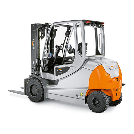
Your truck Description of the truck General The STILL RX60 35-50 is an electrically driv- en counterbalanced truck with a rear swing axle. The truck has a load capacity of up to 5.0 tonnes and can also have a load centre of gravity of 600 mm. - Page 19 Foreword Your truck Speed reduction when the fork carriage is ● raised Electrical fork wear protection ● Tilt angle-dependent assistance systems Mast tilt angle display ● Automatic mast vertical positioning ● Load-dependant assistance systems Overload detection ● Dynamic Load Control 1 or Dynamic Load ●...
- Page 20 Drive The STILL RX60 35-50 is driven via both front wheels by maintenance-free three-phase drives in the front axle with 80 volt technology. Power is supplied by a lead-acid battery that can be replaced from the side.
-
Page 21: General
"backwards" drive direction. Acceleration and braking behaviour can be individually selected from three differ- ent driving programmes. The "STILL Easy Control" display-operating unit simplifies daily use of the truck by pro- viding personally configurable favourites. The display-operating unit also monitors the func- tions of the truck. -
Page 22: Conformity Marking
Foreword Your truck Conformity marking The manufacturer uses the conformity mark- ing to document the conformity of the industri- al truck with the relevant directives at the time of placing on the market: CE: in the European Union (EU) ●... -
Page 23: Declaration That Reflects The Content Of The Declaration Of Conformity
Your truck Declaration that reflects the content of the declaration of conformity Declaration STILL GmbH Berzeliusstraße 10 22113 Hamburg Germany We declare that the specified machine conforms to the most recent valid version of the directives specified below: ... -
Page 24: Accessories
Foreword Your truck Accessories Two keys for the key switch (not for trucks ● with the "Switch on via push button" variant) Two keys for the cab (variant) ● A hexagon socket wrench for emergency ● lowering (in the compartment) A special screwdriver for the battery con- ●... - Page 25 Foreword Your truck 56388011527 EN - 06/2024 - 03 9...
-
Page 26: Labelling Points
Foreword Your truck Labelling points IRP-0017-01 CAT. 2G 6301_901-001 10 56388011527 EN - 06/2024 - 03... - Page 27 Foreword Your truck Decal information: Caution / Read the oper- Warning sign: Dangerous electrical voltage ating instructions / Fasten seat belt / Apply Decal information: Load measurement parking brake when leaving the truck / Pas- Warning sign: Cable cross-section sengers are not allowed / Do not jump off if Decal information: Explosion protection no- the truck is tipping over / Lean in the oppo- tice and equipment category...
- Page 28 Foreword Your truck NE PAS OUVRIR EN ZONE DANGEREUSE DON'T OPEN IN HAZARDOUS AREA 0044 S.r.l. 20812 LIMBIATE (MB) ‒ Via Marconi, CBH ‒ 5 II 573714 3 Year 20 Ex d IIC T II 2 (1) GD Ex tb IIIC T °C Db IP66 ATEX 043X...
-
Page 29: Marking Of Trucks In Accordance With "Dguv Rule 113-006" In Germany
Foreword Your truck Decal information: Hydraulic oil tank Decal information: StVZO (German Road Warning sign: Do not stand underneath the Traffic Licensing Regulations) information fork/Do not stand on the fork Nameplate with CE labelling Warning sign: Danger due to shearing/Dan- Decal information: Battery service ger due to high fluid pressure Decal information: Regular testing... -
Page 30: Nameplate
Foreword Your truck Nameplate The truck can be identified from the informa- tion on the nameplate. Model Serial number Address of manufacturer Year of manufacture Empty weight in kg Maximum permissible battery weight [kg] Minimum permissible battery weight [kg] Ballast weight [kg] ATEX number or approval number Miretti job number... -
Page 31: Stvzo (Road Traffic Licensing Regulations) Information
Foreword Your truck StVZO (Road Traffic Licensing Regulations) information This label includes information on the weight and load distribution of the truck in kg. Tare weight Total permissible weight Permitted front axle load Permitted rear axle load Payload 56388011527 EN - 06/2024 - 03 15... -
Page 32: Nameplate Of The Pressure-Tight Housing
Foreword Your truck Nameplate of the pressure-tight housing The flame proof enclosures are marked with a nameplate. The data on the plate corresponds to the approved area of application for the flame proof enclosure. The plate must be posi- 0044 S.r.l. -
Page 33: Nameplate Of The Battery
Foreword Your truck Nameplate of the battery The nameplate of the battery is mounted on the battery tray. The information on this name- plate describes the permitted area of use of the battery. For use in potentially explosive areas, – only use explosion-protected batteries that are approved for the area in which the truck is to be used. - Page 34 Foreword Your truck Explosion-protected battery from suppli- Model Capacity Nominal voltage Number of cells Serial number HAWKER ATEX test number ® Service weight Tray number Approved area of use Address of manufacturer Explosion protection notice NOTE In this example, the company HAWKER ®...
-
Page 35: Diagnostic Interface
Foreword Your truck Diagnostic interface The truck is equipped with a diagnostic inter- face for monitoring and reading out the truck control unit. Only the authorised service cen- tre may operate the diagnostic interface. The diagnostic interface is identified by the decal information (see illustration). -
Page 36: Using The Truck
Foreword Using the truck Using the truck Basic principles for use in poten- tially explosive areas DANGER Risk of explosion due to use in unap- proved areas! The truck may be operated only in the potentially explosive areas for which it is approved. - Page 37 Foreword Using the truck Gases and vapours are assigned to temper- ature classes on the basis of their ignition temperature. This enables ignition caused by overheated equipment surfaces to be preven- ted. Division of potentially explosive areas for gases, vapours and fumes Potentially explosive areas for flammable gases, vapours and fumes are divided into zones 0, 1 and 2.
- Page 38 Foreword Using the truck ted truck. Truck requirements depend on the zone in which it is intended to be operated. Equipment in group II Zone Category Description II 1G Permanent, long-term or frequent dangerous explosive II 1D atmosphere in the form of a flammable dust cloud II 2G Occasional dangerous explosive atmosphere in the form II 2D...
-
Page 39: Basic Principles For Use In Areas Where A Risk Is Posed By Explosive Materials
Foreword Using the truck Temperature classes Temperature class Ignition temperature range Maximum surface temperature > 450°C 450°C > 300°C to 450°C 300°C > 200°C to 300°C 200°C > 135°C to 200°C 135°C > 100°C to 135°C 100°C > 85°C to 100°C 85°C Basic principles for use in areas where a risk is posed by explo- sive materials DANGER... - Page 40 Foreword Using the truck Transporting explosive materials – Transport explosive materials carefully and cautiously, and in accordance with the com- pany directives for handling explosive mate- rials and for the area of use. Avoid applying the following stresses to explo- sive materials: Jerking ●...
-
Page 41: Temperature Classes
Foreword Using the truck to counteract dangerous interactions between explosive material packaged in a manner suit- able for shipping, or unpackaged explosive material, detonating cords and the truck. "Protected trucks" are trucks fitted with pro- tective devices to counteract dangerous inter- actions between explosive material packaged in a manner suitable for shipping and the truck. -
Page 42: Commissioning
Foreword Using the truck Grinding ● Throwing ● Only transport explosive materials in pack- aging suitable for shipping or in thoroughly sealed, closed containers. This does not apply to objects containing explosive materials that are authorised for transportation without pack- aging in accordance with the national danger- ous goods regulations. -
Page 43: Proper Use During Towing
Foreword Using the truck NOTE For explanations of the individual areas, see the sections "Basic principles for use in poten- tially explosive areas" or "Basic principles for use in areas where a risk is posed by explo- sive materials". If the truck is to be used for purposes other than those specified in the operating instruc- tions, the approval of the manufacturer and, if applicable, the relevant regulatory authorities... - Page 44 Foreword Using the truck DANGER There is a risk of fatal injury from falling off the truck while it is moving! It is prohibited to carry passengers on the truck. DANGER Risk of tipping over if the truck tilts! – Do not perform stacking or unstacking operations when on inclined surfaces or HGV ramps.
- Page 45 Foreword Using the truck Improper use: use in areas where a risk is posed by explo- sive materials The operating company or driver, and not the manufacturer, is liable for any hazards caused by improper use. Use for purposes other than those described in these operating instructions is prohibited.
-
Page 46: Place Of Use: Use In Potentially Explosive Areas
Foreword Using the truck Areas with temperature classes in which the ● truck is not specifically approved for use as listed in the data on the nameplate Areas where a risk is posed by explosive ● materials for the purpose of towing trailers, if these trailers are not also converted to carry explosive materials. - Page 47 Foreword Using the truck NOTE More information concerning the requirements for conductive or dissipative flooring can be found in the guidelines relating to electrostatic hazards "CLC/TR 60079-32-1". General The truck is approved in accordance with Di- rective 2014/34/EU for use in potentially ex- plosive areas.
- Page 48 Foreword Using the truck protection must be provided on the truck. If in doubt, contact the relevant authorities. NOTE Please observe the definition of the following responsible person: "operating company". Relationship between zones and equip- ment categories for industrial trucks Zone 1 –...
-
Page 49: Place Of Use: Use In Areas At Risk From Explosive Substances
Foreword Using the truck Place of use: use in areas at risk from explosive substances DANGER Risk of explosion due to use in unap- proved areas! The truck may be operated only in areas for which it is approved. – Check the area of use by comparing it with the nameplate information. - Page 50 Foreword Using the truck operating instructions; see the section entitled "Roadways" in the "Driving" chapter. Driving on upward and downward gradients is permitted, provided the stipulated data and specifications are observed. The truck is suitable for indoor and outdoor use in countries ranging from the Tropics to Nordic regions (temperature range: -10°C to +40°C).
- Page 51 Foreword Using the truck E 2 areas in which explosive materials: Do not come into contact with apparatus ● and/or operating materials, by design or as a result of a procedure May only occasionally be generated in the ● form of dust, vapour, condensate, sublimate or in other forms.
- Page 52 Foreword Using the truck foreseeable only for short periods of time in exceptional cases and with good reasons during normal operation of the plant. This includes: ○ Boundary areas of C0CP1 where the presence of powder residues or fumes containing explosive materials in the ambi- ent air can be entirely excluded under nor- mal operating conditions and where safety measures are complied with.
-
Page 53: Parking In Temperatures Below -10 °C
Foreword Using the truck Parking in temperatures below -10 °C CAUTION Batteries may freeze or switch off! If the truck is parked in an ambient temperature of below -10°C for an extended period, the batteries will cool down. For lead-acid batteries, the electrolyte can freeze and damage the batteries. - Page 54 Foreword Using the truck WARNING The use of working platforms is regulated by national law. The use of working platforms is only permitted by virtue of the jurisdiction in the country of use. – Observe national legislation. – Before using working platforms, consult the na- tional regulatory authorities.
-
Page 55: Information About The Documentation
Foreword Information about the documentation Information about the documentation Scope of the documentation Original operating instructions of the truck ● Original operating instructions of the dis- ● play-operating unit Operating instructions of the installed var- ● iants that are not mentioned in the afore- mentioned original operating instructions "CO"operating instructions or inserts (de- ●... -
Page 56: Supplementary Documentation
Foreword Information about the documentation Store all documentation safely. Hand over the documentation to the next operating company if the truck is transferred or sold. NOTE Please note the definition of the following re- sponsible persons: "operating company" and "driver". Thank you for reading and complying with these operating instructions. -
Page 57: Issue Date And Topicality Of The Operating Instructions
The issue date and the version of these op- erating instructions can be found on the title page. STILL is constantly engaged in the further de- velopment of trucks. These operating instruc- tions are subject to change, and any claims based on the information and/or illustrations contained in them cannot be asserted. -
Page 58: List Of Abbreviations
Foreword Information about the documentation CAUTION Indicates procedures that must be strictly adhered to in order to prevent material damage and/or destruc- tion. NOTE For technical requirements that require special attention. ENVIRONMENT NOTE To prevent environmental damage -protection information For components, points and procedures rele- vant to explosion protection List of abbreviations This list of abbreviations applies to all types... - Page 59 Foreword Information about the documentation Abbrevi- Meaning Explanation ation European Community European standard European Federation of Materials Han- Fédération Européene de la Manutention dling and Storage Equipment maximum Force Maximum power German authority for monitoring/issuing regulations for worker protection, environ- Gewerbeaufsichtsamt mental protection, and consumer protec- tion...
-
Page 60: Definition Of Directions
Foreword Information about the documentation Abbrevi- Meaning Explanation ation Confirms conformity with the product-spe- UKCA United Kingdom Conformity Assessed cific directives that apply in the United Kingdom (UKCA labelling) Verband der Elektrotechnik Elektronik In- German technical/scientific association formationstechnik e. V. Verein Deutscher Ingenieure German technical/scientific association Verband Deutscher Maschinen- und Anla- German Mechanical Engineering Industry... -
Page 61: Schematic Views
Foreword Information about the documentation Schematic views View of functions and operating proce- dures At many points in this documentation, the (mostly sequential) operation of certain func- tions or operating procedures is explained. Schematic diagrams of a counterbalance truck are used to illustrate these procedures. -
Page 62: Environmental Considerations
Foreword Environmental considerations Environmental considerations Packaging During delivery of the truck, certain parts are packaged to provide protection during trans- port. This packaging must be removed com- pletely prior to initial start-up. ENVIRONMENT NOTE The packaging material must be disposed of properly after delivery of the truck. -
Page 63: Safety
Safety... -
Page 64: Definition Of Responsible Persons
Safety Definition of responsible persons Definition of responsible persons Operating company General The operating company is the natural or legal person who operates the truck or on whose authority the truck is used. The operating company must ensure that the truck is used only for its proper purpose and in compliance with the safety regulations set out in these operating instructions. -
Page 65: Competent Person For Explosion Protection Checks
Safety Definition of responsible persons Working with explosive materials The operating company must prepare a writ- ten company directive, in an understandable format and in the relevant language for the employees operating the truck, containing in- formation about: The applicable safety regulations for transporting explosive materials on com- pany premises The course of action to take if the truck... -
Page 66: Drivers
They must also regu- larly refresh their knowledge The competent person is permitted to work on industrial trucks manufactured by STILL that have been converted by Miretti. Drivers This truck must only be driven by persons who... - Page 67 Safety Definition of responsible persons Have received instruction on explosion-pro- ● tection regulations and rules of behaviour in areas at risk of explosions Be assigned to drive this truck ● If the driver has been trained in accordance with the BGG (General Employers' Liability Insurance Association Act) 925, their training meets the training requirements under section 3 of the Health and Safety at Work Act and...
- Page 68 Safety Definition of responsible persons to be lifted. Sturdy footwear must be worn to ensure safe driving and braking. The driver must wear antistatic clothing and footwear while working in potentially explosive areas. The requirements for antistatic clothing are defined in the following standards: Shoes ●...
-
Page 69: Basic Principles For Safe Operation
Safety Basic principles for safe operation Basic principles for safe operation Insurance cover on company premises In many cases, company premises are restric- ted public traffic areas. NOTE The business liability insurance should be re- viewed to ensure that, in the event of any damage caused in restricted public traffic areas, there is insurance cover for the truck in respect of third parties. - Page 70 Safety Basic principles for safe operation We warn against installing and using restraint systems that have not been approved by the manufacturer. – Contact the authorised service centre be- fore converting or retrofitting restraint sys- tems. DANGER Risk of explosion from additional bores in the battery hood! Explosive gases can escape and can lead to potentially fatal injuries if they...
-
Page 71: Changes To The Overhead Guard And Roof Loads
Safety Basic principles for safe operation ○ Operating instructions Modifications must be designed, checked ● and implemented by a design office that specialises in industrial trucks. The design office must comply with the standards and directives valid at the time that modifica- tions are made. -
Page 72: Damage, Defects And Misuse Of Safety Systems
Safety Basic principles for safe operation parts, attachments and accessories supplied by other companies have not been tested and approved by STILL. CAUTION Installation and/or use of such products may there- fore have a negative impact on the design features of the truck and thus impair active and/or passive driving safety. -
Page 73: Tyres
Safety Basic principles for safe operation Tyres DANGER Risk of explosion! In potentially explosive areas, wheels and tyres that do not meet explosion- protection regulations may lead to explo- sions in the surrounding atmosphere. – Only use approved, electrically con- ductive tyre types. -
Page 74: Medical Equipment
Safety Basic principles for safe operation Changing rim wheel parts ● Combining rim wheel parts from different ● manufacturers Therefore, the above-mentioned factors are prohibited. The following rules must be observed to en- sure stability: – Only use tyres with equal and permitted lev- els of wear on the same axle. -
Page 75: Exercise Caution When Handling Gas Springs And Accumulators
Safety Basic principles for safe operation Medical equipment, such as pacemakers or hearing aids, may not work properly when the truck is in operation. – Ask your doctor or the manufacturer of the medical equipment to confirm that the medical equipment is sufficiently protected against electromagnetic interference. - Page 76 Safety Basic principles for safe operation In addition, be aware that the load centre of gravity may shift as a result of dynamic forces, such as braking. A load that is other- wise resting safely on the fork arms may move forwards and fall.
-
Page 77: Residual Risk
Safety Residual risk Residual risk Residual dangers, residual risks DANGER Risk of explosion in the event of fire or smouldering! In the worst case scenario, polluted, damaged or defective components can result in fire or smouldering. If you smell fire: –... - Page 78 Safety Residual risk Risks can include: Escape of consumables due to leakages, ● rupture of lines and containers etc. Risk of accident when driving over difficult ● ground such as gradients, very smooth or uneven surfaces, or areas with poor visibili- ty etc.
-
Page 79: Special Risks Associated With Using The Truck And Attachments
Safety Residual risk – Always transport unstable loads in suitable containers. – Always drive slowly when cornering. – Drive with the load lowered. – Even with sideshifts, align the load as cen- trally as possible with the truck and trans- port in this position. -
Page 80: Overview Of Hazards And Countermeasures
Safety Residual risk Overview of hazards and countermeasures NOTE This table is intended to help evaluate the hazards in your facility and applies to all drive types. It does not claim to be complete. – Observe the national regulations for the country in which the truck is being used. - Page 81 Safety Residual risk Hazard Course of action Check note Notes √ done - Not applicable Impermissible usage Provide operating in- German Ordinance on (improper usage) structions Industrial Safety and Health (BetrSichV) and German Health and labour protection law (ArbSchG) Written notice of in- German Ordinance on struction to driver Industrial Safety and...
-
Page 82: Danger To Employees
Safety Residual risk Hazard Course of action Check note Notes √ done - Not applicable DGUV rule 113-001 and observe the oper- ating instructions When operating driverless transport systems Roadway quality inad- Clean/clear roadways German Ordinance on equate Industrial Safety and Health (BetrSichV) Loading equipment in- Reposition load on pal-... - Page 83 Safety Residual risk The design and equipment of the truck comply with the standards and directives required for CE conformity. The design and equipment al- so comply with the standards and directives necessary for the UKCA compliance that is required in the United Kingdom. The design and equipment are therefore not part of the required scope of the hazard assessment.
-
Page 84: Safety Tests
Safety Safety tests Safety tests Carrying out regular inspections on the truck The operating company must ensure that the truck is checked by a specialist at least once a year or after particular incidents. As part of this inspection, the technical condi- tion of the truck must be completely tested with regard to accident safety. -
Page 85: Explosion-Protection Checks
Safety and Health once every three years by a competent person; see also "Definition of re- sponsible persons - Competent person". How- ever, as a manufacturer, STILL recommends Nächste Prüfung that this test is carried out annually. If the truck is subject to harsh application conditions, the interval between tests must be shortened. -
Page 86: Testing The Electrical System
Safety Safety tests Testing the electrical system DANGER Risk of explosion! Trucks to be used in potentially explo- sive areas are designed for certain ex- plosion groups, categories and temper- ature ranges. In potentially explosive areas, trucks that do not meet explosion- protection regulations may lead to explo- sions in the surrounding atmosphere. - Page 87 Safety Safety tests NOTE The truck's electrical system and drive batter- ies must be checked separately. Test values for the drive battery Recommended Nominal volt- Component Measurements Test values test voltage age U Batt 50 VDC 24 volts > 1200 Ω Batt+ Battery 100 VDC Battery tray 48 volts...
-
Page 88: Safety Regulations For Handling Consumables
Safety Safety regulations for handling consumables Safety regulations for handling consumables Permissible consumables WARNING Consumables can be dangerous! – Observe general information and safety informa- tion regarding the use of consumables. – Refer to the chapter entitled "Safety regula- tions for handling consumables". –... -
Page 89: Hydraulic Fluid
Safety Safety regulations for handling consumables WARNING Prolonged intensive contact with the skin can result in dryness and irritate the skin! – Avoid contact and consumption. – Wear protective gloves. – After any contact, wash the skin with soap and water, and then apply a skin care product. -
Page 90: Battery Acid
Safety Safety regulations for handling consumables WARNING These fluids are pressurised during op- eration of the truck and are hazardous to your health. – Do not allow the fluids to come into contact with the skin. – Avoid inhaling spray. –... -
Page 91: Disposal Of Consumables
Safety Safety regulations for handling consumables WARNING Battery acid contains dissolved sulphuric acid. This is corrosive. – When working with battery acid, use appropriate PSA (rubber gloves, apron, protection goggles). – When working with battery acid, nev- er wear a watch or jewellery. –... -
Page 92: Emissions
Safety Emissions Emissions The values specified apply to a standard truck (compare the specifications in the "Technical data" chapter). Different tyres, lift masts, addi- tional units etc. may produce different values. Noise emissions The values were determined based on meas- uring procedures from the standard EN 12053 "Safety of industrial trucks - Test methods for measuring noise emissions", based on... - Page 93 Safety Emissions Vibrations The vibrations of the machine have been de- termined on an identical machine in accord- ance with the standards DIN EN 13059 "Safe- ty of industrial trucks - Test methods for meas- uring vibration" and DIN EN 12096 "Mechani- cal vibration - Declaration and verification of vibration emission values".
- Page 94 – Charge batteries only outside of po- tentially explosive areas. Radiation In accordance with the guide- lines DIN EN 62471:2009-03 (VDE 0837-471:2009-03), the STILL Safety- Light and the warning zone light (variant) are assigned to risk group 2 (medium risk) due to their photobiological hazard potential. 78...
-
Page 95: Overviews
Overviews... -
Page 96: Overview
Overviews Overview Overview 6301_003-020 80 56388011527 EN - 06/2024 - 03... - Page 97 Overviews Overview Lift mast Fork carriage Overhead guard Lift cylinder Driver's compartment Rear lighting Battery (in the battery compartment) Battery door Drive axle with traction motors Steering axle Front lighting Towing device Fork arms Counterweight NOTE In the category 2 version, a flame proof en- closure is located on the counterweight (14).
-
Page 98: Driver's Compartment
Overviews Driver's compartment Driver's compartment 6301_901-003_V2 82 56388011527 EN - 06/2024 - 03... - Page 99 Compartment Brake pedal Screen wash pump button (category-2 Bottom plate version) Pneumatic signal horn Display-operating unit "STILL Easy Control" The pneumatic horn is only available on cat- Operating devices for hydraulic and drive egory-2 trucks. functions Steering column adjustment lever Compartment for storing the operating in- Reset button...
-
Page 100: Shelves
Overviews Shelves Shelves 6219_901-015_V3 WARNING Risk of accident caused by blocked pedals! Objects may fall into the footwell during travel as a result of steering or braking. They can slip between and under the pedals (3, 4). They then block the pedals. - Page 101 Overviews Shelves The truck is equipped with a compartment (2) for the operating instructions and the hex- agon socket wrench for emergency lowering. The safety officer must decide whether the operating instructions and the hexagon socket wrench may be carried in potentially explosive areas.
-
Page 102: Operating Devices And Display Elements
Brightness sensor Right-hand favourites bar "STILL Easy Control" is a third-generation dis- play-operating unit for industrial trucks. It is used as an operating device for the usu- al functions of the truck, such as controlling lighting and windscreen wiper functions and adjusting the driving dynamics. - Page 103 – For information about the other display op- tions, see the original operating instructions entitled "STILL Easy Control display-operat- ing unit". The display-operating unit is attached to the armrest, except in trucks equipped with mul- ti-lever operation.
-
Page 104: Explosion-Protection Warning Lights
Overviews Operating devices and display elements Explosion-protection warning lights DANGER Risk of explosion! During operation, the surface tempera- tures and insulation values of various components are monitored by sensors. – Do not operate the truck when a warning light is illuminated. The explosion-protection warning lights are lo- cated on the left-hand post, in the driver's field of view. - Page 105 Overviews Operating devices and display elements Push-and-turn version 6219_901-018_ Turn version NOTE This battery isolating switch can be secured in the "OFF" position by using a lead seal or a padlock to prevent the switch from being actuated without authorisation. 6219_901-006_V2 56388011527 EN - 06/2024 - ...
-
Page 106: Emergency Off Switch
Overviews Operating devices and display elements Emergency off switch The emergency off switch (1) is situated on the right-hand side of the steering column. It disconnects the drives from the power supply. Do not use this switch to park the truck safely. Reset button ... -
Page 107: Multi-Lever Operation
Overviews Operating devices and display elements Multi-lever operation 6219_003-004_V3 Drive direction switch Operating lever for attachments (variant) "Lift/lower" operating lever Function key for the "5th or 6th function" "Tilt" operating lever (variants) Operating lever for attachments (variant) Signal horn button Function key for the "5th function" (variant) NOTE In the dual-pedal version (variant), the drive direction switch (1) is used exclusively to acti-... -
Page 108: Double Mini-Lever
Overviews Operating devices and display elements Double mini-lever Drive direction switch "F1" function key Cross lever "Attachments" "Lift mast" 360° lever Function key for the "5th function" Display field for the hydraulic functions Signal horn button 92 56388011527 EN - 06/2024 - 03... - Page 109 Overviews Operating devices and display elements NOTE In the dual-pedal version (variant), the drive ● direction switch (1) is used exclusively to activate the cruise control function (variant). The drive direction is selected exclusively via the pedals in the dual-pedal version. The authorised service centre can assign ●...
-
Page 110: Triple Mini-Lever
Overviews Operating devices and display elements Triple mini-lever Drive direction switch Signal horn button "Auxiliary hydraulics 1" operating lever "F1" function key "Auxiliary hydraulics 2" operating lever "Lift mast" 360° lever Function key for the "5th function" Display field for the hydraulic functions 94 56388011527 EN - 06/2024 - ... - Page 111 Overviews Operating devices and display elements NOTE In the dual-pedal version (variant), the drive ● direction switch (1) is used exclusively to activate the cruise control function (variant). The drive direction is selected exclusively via the pedals in the dual-pedal version. The authorised service centre can assign ●...
-
Page 112: Quadruple Mini-Lever
Overviews Operating devices and display elements Quadruple mini-lever Drive direction switch Signal horn button "Tilt" operating lever "F1" function key "Auxiliary hydraulics 1" operating lever "Lift/lower" operating lever "Auxiliary hydraulics 2" operating lever Display field for the hydraulic functions Function key for the "5th function" 96 56388011527 EN - 06/2024 - ... - Page 113 Overviews Operating devices and display elements NOTE In the dual-pedal version (variant), the drive ● direction switch (1) is used exclusively to activate the cruise control function (variant). The drive direction is selected exclusively via the pedals in the dual-pedal version. The authorised service centre can assign ●...
-
Page 114: Fingertip
Overviews Operating devices and display elements Fingertip Signal horn button Drive direction switch LED for the "5th function" "Lift/lower" operating lever Function key for the "5th function" "Tilt" operating lever LED for the "Clamp release" "F1" function key Operating lever for "Auxiliary hydraulics 1" LED for "F1"... -
Page 115: Joystick 4Plus
Overviews Operating devices and display elements Joystick 4Plus 6219_003-210_V2 Horizontal rocker button for the "3rd and LED for the "clamp release" (variant) 4th hydraulic function": tilting the lift mast Slider for the "4th hydraulic function" Pictograms for the hydraulic functions: lift- Vertical rocker button for the "drive direction" ing, lowering and sideshift Shift key "F"... -
Page 116: Travel Direction Selector And Indicator Module (Variant)
Overviews Operating devices and display elements Travel direction selector and in- dicator module (variant) The travel direction selector and indicator module is located on the steering column be- low the steering wheel. NOTE If the drive direction switch on the operating device is defective and the truck stops in a danger area, the drive direction selection lever on the travel direction selector and indicator... -
Page 117: Operation
Operation... -
Page 118: Checks And Tasks Before Daily Use
Operation Checks and tasks before daily use Checks and tasks before daily use Visual inspections and function checking WARNING Risk of injury from falling off the truck! When climbing onto the truck, there is a risk of getting stuck or slipping and falling. - Page 119 Operation Checks and tasks before daily use Component Course of action Perform a visual inspection to ensure that the Load chains chains are intact and have adequate and even ten- sion. Ensure that the attachments are mounted correctly in accordance with the operating instructions from the manufacturer.
- Page 120 Operation Checks and tasks before daily use Component Course of action Perform a visual inspection for integrity and defor- mation. Check that the interlock is in good condition and is Battery door working correctly. Check the close function. Close. Check that the interlock is in good condition and is working correctly.
- Page 121 "Adjusting the swivelling display-operating unit (variant)" in this chapter. Perform a visual inspection for integrity. Ensure cleanliness. Make sure that the antistatic belt(3) is still long Antistatic belt (3), corona electrode (4) enough to touch the ground in all situations. (See the following illustration.) The discharge wires of the corona electrode (4)
-
Page 122: Climbing Into And Out Of The Truck
Operation Checks and tasks before daily use Climbing into and out of the truck WARNING Risk of injury when climbing into and out of the truck due to slipping, striking parts of the truck or becom- ing stuck! If the footwell cover is very dirty or smeared with oil, there is a risk of slipping. -
Page 123: Climbing In And Out Of Trucks When The Driver's Compartment Is Raised (Variant)
Operation Checks and tasks before daily use To assist with climbing into and out of the truck, use the step (1), use the footwell (2) as a step and use the handle (4) for support. The post of the overhead guard (3) can also be used for support. - Page 124 Operation Checks and tasks before daily use WARNING Risk of injury when jumping out of the truck! If your clothing or jewellery (e.g. watch, ring etc.) be- comes stuck on a component while you are jumping into or out of the truck, this can lead to serious inju- ries (from falling, loss of fingers etc.).
-
Page 125: Safety Information Regarding Electrostatic Charge
Operation Checks and tasks before daily use Always climb out of the truck backwards: – If the truck has a driver's cab, open the driv- er's door. – Grip the handle (2) with your left hand and do not let go. –... -
Page 126: Adjusting The Steering Column
Operation Checks and tasks before daily use Adjusting the steering column – Pull up and hold the lever (2) for steering column adjustment. – Position the steering column (1), then push the lever down again and allow the steering column to engage. DANGER Risk of accident! –... -
Page 127: Adjusting The Swivelling Display-Operating Unit (Variant)
Operation Checks and tasks before daily use Turn version – Turn the battery isolating switch (1) in a clockwise direction to the "ON" position. 6219_901-006_V2 Adjusting the swivelling display- operating unit (variant) Depending on the equipment, the swivelling display-operating unit can be located in the following positions: On the right-hand A-pillar ●... - Page 128 Operation Checks and tasks before daily use To change the resistance for adjusting the dis- play-operating unit, there are two socket head screws (2) on the support for the display-op- erating unit. The hexagon socket wrench for emergency lowering can be used to loosen or tighten the socket head screws (2).
-
Page 129: Function Checking Of The Assistance Systems
Operation Checks and tasks before daily use Function checking of the assis- tance systems Checking the assistance systems is one of the checks and tasks that must be performed before daily use. It is important to know which assistance systems are fitted to the truck. The assistance systems are listed in the display- operating unit. -
Page 130: Unlock The Emergency Off Switch
Operation Checks and tasks before daily use Unlock the emergency off switch – Turn the emergency off switch (1) clockwise until it pops out. Checking the emergency off function WARNING No electric braking assistance is available when the emergency off switch is actuated! Actuating the emergency off switch disconnects the drives from the power supply. -
Page 131: Operating The Signal Horn
Operation Checks and tasks before daily use Operating the signal horn The signal horn is used to warn people against imminent danger or to announce your intention to overtake. – Press the signal horn button (1). The signal horn sounds. 56388011527 EN - 06/2024 - ... -
Page 132: Using The Driver's Cab
Operation Checks and tasks before daily use Operating the pneumatic signal horn The signal horn is used to warn people against imminent danger or to announce your intention to overtake. Depending on the application and configura- tion, the truck is equipped with a pneumatic signal horn. -
Page 133: Checking The Brake Oil Level
Operation Checks and tasks before daily use DANGER Risk of fatal injury in the event of falling from the truck if it tips over! In order to prevent the driver from sliding underneath the truck and being crushed if the truck tips over, a restraint system must be in place and must be used. - Page 134 Operation Checks and tasks before daily use – Lift the cover (1) and fold it up. The brake oil level must be within the area (2) of the taper up to the neck. Do not top up the brake oil. – If the brake oil level is lower than it should be or has visibly dropped, contact the au- thorised service centre.
- Page 135 Operation Checks and tasks before daily use 56388011527 EN - 06/2024 - 03 119...
-
Page 136: Checking The Brake System For Correct Function
Operation Checks and tasks before daily use Checking the brake system for correct function DANGER Risk of accident in the event of failure of the brake system! If the brake system fails, the truck will be insufficient- ly braked. – Do not operate the truck if the brake system is faulty. - Page 137 Operation Checks and tasks before daily use – Accelerate the unladen truck in a clear area. – Press the brake pedal (1) firmly. The truck must decelerate noticeably. Checking the parking brake on a gradi- ent or a lorry ramp DANGER Risk to life if the truck rolls away! If the parking brake is not applied, the truck could run people over.
-
Page 138: Warming Up The Hydraulic Oil At Cold Ambient Temperatures
Operation Checks and tasks before daily use NOTE When the emergency off switch is actuated, note the following: The electric brake is disabled. The truck no ● longer responds to the command issued by the accelerator pedal. The power steering is no longer available. ●... -
Page 139: Checking The Steering System For Correct Function
Operation Checks and tasks before daily use – Actuate all hydraulic lifting functions several times. Limiting the load dynamics to load program 1 during the warm-up phase NOTE During the warm-up phase, the load dynamics are limited to load program 1. The adjacent symbol appears on the display until the warm- up phase is complete. -
Page 140: Driver's Seat
Operation Driver's seat Driver's seat Adjusting the MSG 65/MSG 75 driver's seat WARNING Risk of accident from sudden adjustment of the seat or of the seat backrest! The inadvertent adjustment of the seat or of the seat backrest can lead to uncontrolled movements by the driver. -
Page 141: Adjusting The Seat Backrest
Operation Driver's seat Moving the driver's seat – Raise the lever (1) and hold it in position. – Push the driver's seat into the required po- sition. – Release the lever. – Ensure that the driver's seat is securely en- gaged. - Page 142 Operation Driver's seat Adjusting the MSG 65/MSG 75 seat suspension NOTE The MSG 65/MSG 75 driver's seat is de- signed for people weighing between 45 kg and 170 kg. The driver's seat can be adjusted to suit the weight of the individual driver. To ob- tain optimal settings for the seat suspension, the driver must perform the adjustment whilst sitting on the seat.
- Page 143 Operation Driver's seat Adjusting the lumbar support (variant) NOTE The lumbar support can be adjusted to suit the contours of the individual driver's spine. Adjusting the lumbar support moves a convex support cushion into the upper or lower part of the backrest.
-
Page 144: Adjusting The Msg 95 Driver's Seat
Operation Driver's seat Switching the seat heater (variant) on and off NOTE The seat heater only works when the driver is sitting on the driver's seat. – Switch the seat heater (8) on or off using the switch. 6321_003-041_V3 Adjusting the MSG 95 driver's seat WARNING Risk of accident from sudden adjustment of the seat... - Page 145 Operation Driver's seat WARNING To obtain optimum seat cushioning, you must adjust the seat suspension to your own body weight. This course of action is better for your back and protects your health. – To avoid injuries, keep the swivel area of the seat clear of objects.
- Page 146 Operation Driver's seat Adjusting the damping of the seat sus- pension The suspension comfort can be adjusted as desired by the driver. – Turn the adjusting lever (3) until the desired setting is reached. 6301_003-152 Adjusting to the driver's weight and ad- ...
- Page 147 Operation Driver's seat Adjusting the longitudinal horizontal suspension If the driver's seat is equipped with the "longi- tudinal horizontal suspension" variant, impacts in the drive direction are damped by additional seat suspension. The locking lever (5) on the left-hand side of the driver's seat activates and locks the longitudinal horizontal suspension.
- Page 148 Operation Driver's seat Adjusting the backrest extension – Adjust the backrest extension (7) by pulling it out and pushing it into the desired posi- tion. The engagement can be felt. To remove the backrest extension, move it past the end stop by firmly pushing it upwards. 6301_003-156 Switching the seat heater (variant) on ...
- Page 149 Operation Driver's seat Adjusting the seat angle The longitudinal tilt of the seat base can be adjusted individually. – To adjust the seat angle, pull the handle (9) upwards. By simultaneously applying pressure to or re- moving pressure from the front or rear seat base, it tilts into the desired position.
-
Page 150: Seat Belt
DANGER Risk of injury if the truck tips over! Even if an approved restraint system is in use, there is still a residual risk that the driver could be injured if the truck tips over. This risk of injury can be reduced through the combined use of the re- straint system and the seat belt. - Page 151 Operation Driver's seat NOTE The buckle has a buckle switch. When the belt was not fastened, the following occurred: The message Close seat belt ● appears on the display-operating unit. The truck will not drive at speeds faster ● than 4 km/h.
- Page 152 Operation Driver's seat Special feature for trucks with HSR re- straint systems (variant) If the bracket is not closed, the message appears Close restraint system in the display. Fastening on a steep slope The automatic blocking mechanism prevents the belt from being extended whenever the truck is on a steep gradient.
-
Page 153: Adjusting The Armrest
Operation Driver's seat Malfunction due to cold – If the buckle or belt retractor are frozen, thaw the buckle or the belt retractor and dry the parts. This prevents the parts from refreezing. CAUTION The seat belt may be damaged by heat! Do not subject the buckle or belt retractor to exces- sive heat when thawing. - Page 154 Operation Driver's seat – Tighten the hand wheel by turning to the right. – Check that the armrest is firmly attached. 138 56388011527 EN - 06/2024 - 03...
-
Page 155: Switching On
Operation Switching on Switching on Switching on using the key switch WARNING All checks and tasks required before daily use must have been performed without any defects being iden- tified before switching on the truck. – Perform the "visual inspections and functional checks". -
Page 156: Switching On Via Push Button (Variant)
Operation Switching on – Refer to the chapter entitled "Display mes- sages". NOTE After connecting the battery, the correct charge state may not be displayed until the battery is placed under load by driving or lifting operations. Switching on via push button (variant) WARNING All checks and tasks required before daily use must... - Page 157 Operation Switching on – To switch off the truck, press the push but- ton (1) and hold for 1 second. NOTE For the variant with "Access authorisation with PIN code", see ● the relevant section. "FleetManager", see the "original operating ● instructions for FleetManager". 56388011527 EN - 06/2024 - ...
-
Page 158: Display-Operating Unit
Operation Display-operating unit Display-operating unit Operating the display-operating unit 08:20 7° 2,71 km/h 6219_003-310 The display-operating unit is operated using the control and enter keys (5...8) and the soft- keys (4, 10). The display (2) shows informa- tion about the current driving programme, load programme and the configuration of the fa- vourites bars (1, 3). -
Page 159: Alternative Position Of The Display-Operating Unit (Variant)
Operation Display-operating unit Functions of the control and enter keys Designation Position Functions The softkeys correspond to the adjacent functions or input options. If functions have been stored in the favourites bars (1, 3), these functions can be switched on and off by pressing the Softkeys 4, 10 adjacent softkey. - Page 160 Operation Display-operating unit Required field of vision The illustrations below provide an overview of the requirements for the dimensions and the position of the additional devices or monitors in order to ensure an adequate field of vision. Maximum height of devices or monitors. Minimum distance between the under- sides of the devices or monitors.
-
Page 161: Access Authorisation With Pin Code (Variant)
Operation Display-operating unit Access authorisation with PIN code (variant) Trucks equipped with the "Access authorisa- tion with PIN code" variant are protected against unauthorised use by a PIN code. So that the same truck can be used by different drivers, individual PIN codes can be specified. An initial PIN code of "11111"... -
Page 162: Access Authorisation For The Fleet Manager (Variant)
Operation Display-operating unit Changing the PIN codes The fleet manager can change the PIN codes. See also the following section entitled "Access authorisation for the fleet manager (variant)". – Activate the "Access authorisation for the fleet manager". – Press the ... - Page 163 Operation Display-operating unit these settings is protected by a fleet manager password. Three options are available for the "Access authorisation for the fleet manager" variant: No fleet manager password Access to the configuration menus is not enabled. If access is required at a later date, the authorised service centre must set up a fleet manager password.
- Page 164 Operation Display-operating unit – Press the Access authorisa- softkey tion Display settings Configure favourites Truck settings Service Access authorisation Fleet manager 6219_003-267_V2_en The display changes to the Access au- menu. thorisation – Enter the fleet manager password using the softkeys.
- Page 165 Operation Display-operating unit The message Fleet manager access appears. authorisation granted – To confirm, press the softkey. The display returns to the settings menu. If the password entered was incorrect, the Fleet manager message is dis- access authorisation Password incorrect played.
- Page 166 Operation Display-operating unit – Press the scroll buttons until Change password (access menu appears. auth.) – Press the Version list Change password (ac- softkey. cess auth.) – Follow the instructions on the display. Calibration Relieve hydraulics Shock sensor Change password (access auth.) Fleet manager 6219_003-275_en...
-
Page 167: Pre-Shift Check
Operation Pre-Shift Check Pre-Shift Check Description of the Pre-Shift Check (variant) The Pre-Shift Check is a guided dialogue in the display-operating unit. It also helps the driver conduct the necessary "visual inspec- tions and function checking" before everyday use. After the truck has been switched on, the driver must answer questions about the condi- tion of the forklift truck with While the driver is doing this, the truck func-... -
Page 168: Process
The main display contains the message To complete Pre-Shift Check, press This means that the Pre-Shift Check is still active and the truck functions are restricted. – To acknowledge the message, press the 6219_003-265_en softkey. – Switch on and check the function to be tes- ted, e.g. -
Page 169: All Questions
Operation Pre-Shift Check speed. When the parking brake is applied again, the view returns to Pre-Shift Check. At the end of the check, truck functions are restricted if they have been adjusted as a re- action to a negative test result. The message Pre-Shift Check truck restric- shows that truck functions tions active... -
Page 170: Defining The Question Sequence
Operation Pre-Shift Check Is the capacity rating plate present, undamaged, and legible? Is the driver restraint system damaged? Does the horn work? Does the truck lighting work? Do the warning lights work? Is the antistatic belt present and does it have sufficient con- tact with the floor? Is the corona electrode present and clean? Does the parking brake work properly? - Page 171 Operation Pre-Shift Check – Press the softkey. Service – Press the scroll keys until the Pre- menu appears. Shift Check – Press the softkey. Pre-Shift Check Message list Maintenance interval Version list Pre-Shift Check Calibration Fleet manager 6219_003-268_en 56388011527 EN - 06/2024 - ...
-
Page 172: Displaying The History
Operation Pre-Shift Check menu appears. Pre-Shift Check – Press the softkey. Question sequence History Reset restriction Shift start Question sequence Fleet manager 6219_003-269_en Pressing the softkey allows fixed or random question sequences to be selected. The orange activation bar displays the current selection. - Page 173 Operation Pre-Shift Check – Press the softkey. Service – Press the scroll keys until the Pre- menu appears. Shift Check – Press the softkey. Pre-Shift Check Message list Maintenance interval Version list Pre-Shift Check Calibration Fleet manager 6219_003-268_en 56388011527 EN - 06/2024 - ...
-
Page 174: Defining The Shift Start
Operation Pre-Shift Check menu appears. Pre-Shift Check – Press the softkey. History History Reset restriction Shift start Question sequence Fleet manager 6219_003-269_en The Pre-Shift Check display opens. results This display shows all checks and questions that have been answered with the date and Pre-Shift Check results time. - Page 175 Operation Pre-Shift Check NOTE If the truck is equipped with the "FleetManag- er" variant, the shifts are defined on the Fleet- Manager interface. See the relevant operating instructions. – Activate the "Access authorisation for the fleet manager". – Press the ...
- Page 176 Operation Pre-Shift Check menu appears. Pre-Shift Check – Press the softkey. Shift start History Reset restriction Shift start Question sequence Fleet manager 6219_003-269_en In this menu, you can call up the shift to be defined and its start time. The orange activation bar indicates which shifts are activated.
- Page 177 Operation Pre-Shift Check In this menu you can define the shift start. – Enter the time using softkeys 0 to 9 – To , press the button. save Shift start 1 The shift start is now defined. The Pre-Shift Check is always requested from this shift start time.
-
Page 178: Resetting The Truck Restrictions
Operation Pre-Shift Check – Press the scroll button to deactivate the shift. – To confirm, press the button. Shift start 1 The time is shown in grey. The shift is deactivated. The display reverts to the previous menu. There is no activation bar next to this shift. - Page 179 Operation Pre-Shift Check – Press the scroll keys until the Pre- menu appears. Shift Check – Press the softkey. Pre-Shift Check Message list Maintenance interval Version list Pre-Shift Check Calibration Fleet manager 6219_003-268_en menu appears. Pre-Shift Check –...
- Page 180 Operation Pre-Shift Check A question pops up asking if you want to reset the truck restrictions. – To confirm, press the softkey. The full scope of the truck functions is now available. The display reverts to the previous Reset the truck restrictions? The entry remains in the history menu.
-
Page 181: Driver Profiles
Operation Driver profiles Driver profiles Driver profiles (variant) This variant allows up to ten individual driver profiles to be created. The driver is greeted with the selected name after logging in. Once softkey is pressed, the main display appears. Hello, 0,0°... - Page 182 Operation Driver profiles ped with these variants, drivers must select their profiles manually. NOTE Access to the settings menu is only availa- ble if the truck is at a standstill and the park- ing brake is applied. If the parking brake is released prematurely, the settings menu will close.
-
Page 183: Creating Driver Profiles
Operation Driver profiles The orange activation bar displays the current selection. – Press the softkey for the required driver profile. Guido The driver profile is active. The driver is gree- ted with the selected name the next time that Horst the truck is switched on. - Page 184 Operation Driver profiles – Press the soft- Driver profiles key Driver profiles Truck information Display settings Configure favourites Truck settings 6219_003-293_en This menu provides storage space for saving ten driver profiles. – Press the softkey for the required storage location.
-
Page 185: Renaming Driver Profiles
Operation Driver profiles menu is displayed. Driver name – Use the softkeys to enter the desired name. – To confirm, press the button. Driver name The driver profile is active. The driver is gree- ted with the selected name after the next log- Any changes that drivers make to the settings Enter driver name while they are logged in are saved. - Page 186 Operation Driver profiles – Press the Rename driver profiles softkey. Driving programme Rename driver profiles 6219_003-298_en menu is displayed. Driver name – Use the softkeys to enter the desired name. – To confirm, press the button. Driver name Renaming by the fleet manager –...
- Page 187 Operation Driver profiles – Press the Manage driver pro- softkey. files Lift height preselection Auxiliary hydraulics Change PIN codes Manage driver profiles On-board charger Fleet manager 6219_003-296_en – Press the Rename driver pro- softkey. files Rename driver profiles Delete driver profiles Fleet manager 6219_003-297_en...
-
Page 188: Deleting Driver Profiles
Operation Driver profiles menu is displayed. Driver name – Use the softkeys to enter the desired name. – To confirm, press the button. Driver name Enter driver name Horst = Clear = abc -> ABC = Save = Cancel 6219_003-295_en Deleting driver profiles The fleet manager has access authorisation to... - Page 189 Operation Driver profiles – Press the Delete driver profiles softkey. Rename driver profiles Delete driver profiles Fleet manager 6219_003-297_en – Press the softkey for the driver profile to be deleted. The driver profile is deleted. Guido Horst Lisa Driver 4 Available storage position 5 6219_003-294_en...
-
Page 190: Lighting
Symbols for the lighting and their meanings Parking light Headlights Hazard warning system Rotating beacon STILL SafetyLight Warning zone light Front working spotlights Rear working spotlights Roof working spotlights Only the symbols of the lighting devices that are installed in the truck can be selected. -
Page 191: Driving Lights
Operation Lighting Driving lights – To switch on the parking light (1), push the associated Softkey on the display-operating unit. The front side lights and the tail lights light up. – To switch on the driving light (2), press the associated Softkey on the display-operating unit. -
Page 192: Working Spotlights
Operation Lighting Working spotlights Front and rear working spotlights – To switch on the front working spot- lights (3), push the associated Softkey on the display-operating unit. The front working spotlights light up. – To switch off the front working spot- lights (3), push the Softkey again. -
Page 193: Working Spotlight For Reverse Travel (Variant)
Operation Lighting Working spotlight for reverse travel (variant) In this equipment variant, a working spotlight for reverse travel is fitted on the rear of the overhead guard and provides optimum illumi- nation of the roadway during reverse travel. – Press the softkey. - Page 194 Operation Lighting – To switch on the left or right turn indicator, move the lever (1) to the desired direction. 6219_003-098 The turn indicators and the turn indicator dis- play (2) or (3) on the display-operating unit flash. 08:20 – To switch off the turn indicators, push the lever (1) back to the centre position.
-
Page 195: Hazard Warning System
Operation Lighting Hazard warning system Switching the hazard warning system on and off is different for trucks with and without the StVZO (German Road Traffic Licensing Regu- lations) variant. – To switch on the hazard warning system, push the associated Softkey on the display- operating unit. -
Page 196: Stvzo Equipment
This softkey is used to switch off all light- ing devices that are not permitted on roads subject to German traffic regulations (StVO). This relates to the following variants of lighting equipment: STILL SafetyLight and STILL Safety- ● Light 4Plus Warning zone light and warning zone light ●... -
Page 197: Rotating Beacon
WARNING Danger of damage to eyes from look- ing into the STILL SafetyLight® and STILL SafetyLight 4Plus®. Do not look into the STILL SafetyLight® or STILL SafetyLight 4Plus®. STILL SafetyLight® and STILL SafetyLight 4Plus® are visual warning units designed to enable early detection of trucks in driving areas with low visibility (such as drive lanes, high racks), as well as at blind junctions. -
Page 198: Warning Zone Light And Warning Zone Light Plus (Variants)
STILL SafetyLight 4Plus® is mounted on a support on the overhead guard such that it is not affected by jolts and vibrations. Depending on the version, the STILL Safety- Light® projects one or more light-blue light spots in front of or behind the truck and thus warns others about the approaching truck. - Page 199 Operation Lighting The warning zone light projects a light bar next to the truck on both the left-hand side and right-hand side of the truck or even behind the truck. This light bar indicates the danger areas to the sides or rear of the truck while in operation.
-
Page 200: Efficiency And Drive Modes
Therefore, on distances of up to approx. 40 m, lower speeds are reached than would be the case if the efficiency mode was not activated. As in "STILL Classic" mode, the maximum speed is 20 km/h. Blue-Q has no influence on: Maximum speed ●... - Page 201 Operation Efficiency and drive modes Shut-off Seat switch Truck is stationary Drive direction Screen heating *No shut-off for StVZO (German Road Traffic Licensing Regulations) equipment (variant) 56388011527 EN - 06/2024 - 03 185...
-
Page 202: Switching Blue-Q On And Off
Operation Efficiency and drive modes Switching Blue-Q on and off – To switch on Blue-Q efficiency mode, push the softkey The Blue-Q symbol appears on the display/operating unit and Blue-Q efficiency mode is switched on. – To switch off Blue-Q efficiency mode, push the associated softkey again. -
Page 203: Configuring Blue-Q
The orange activation bar appears next to the pushed softkey. The main display button takes you to the main display. STILL Classic and sprint mode The drive modes affect the handling of the truck. Two different drive modes are available: STILL Classic... - Page 204 The symbol disappears and the mode is switched off. The truck is then back in STILL Classic mode. Automatic switch off for sprint mode If the truck is operated in sprint mode at the maximum performance level, the truck will consume more energy.
-
Page 205: Driving
Operation Driving Driving Safety regulations when driving Driving conduct The driver must follow the public rules of the road when driving in company traffic. The speed must be appropriate to the local conditions. For example, the driver must drive slowly around corners, in tight passageways, when driving through swing-doors, at blind spots, or on uneven surfaces. - Page 206 There is a risk of accident! – Do not use devices during travel or when handling loads. – Set the volume so that warning signals can still be heard. WARNING In areas where use of mobile phones is prohibited, use of a mobile phone or radio telephone is not per- mitted.
-
Page 207: Roadways
The required aisle widths depend on the di- mensions of the load. Required aisle widths with pallet Aisle width [mm] With pallet With pallet Model Type 1000x1200 800x1200 crosswise* lengthwise RX60-35/600 6331 4265 4465 RX60-40 6332 4265 4465 RX60-40/600 6333 4265 4465... -
Page 208: Driving On Ascending And Descending Gradients
Operation Driving Driving on ascending and descending gradients WARNING Risk of accident due to the drive unit switching off! Driving up and down long gradients can cause the drive unit to overheat and switch off. The truck will then no longer decelerate when the accelerator ped- al is released and will coast. -
Page 209: Hazardous Areas
Operation Driving height is based on the overall height of the lift mast and the dimensions of the load. Rules for roadways and the working area It is only permitted to drive on routes author- ised for traffic by the operating company or its representatives. -
Page 210: Configuring Drive Programmes A And B
Operation Driving – If the drive programmes are saved as a fa- vourite on a softkey, press the softkey until the number of the desired drive pro- gramme is shown on the display. The number of dynamic bar segments indi- cates the driving dynamics of the selected drive programme. - Page 211 Operation Driving NOTE Access to the settings menu is only availa- ble if the truck is at a standstill and the park- ing brake is applied. If the parking brake is released prematurely, the settings menu will close. – Stop the truck. –...
-
Page 212: Selecting The Drive Direction
Operation Driving – To cancel the setting, press the softkey. The settings return to the most recently saved value. Press the button once to return to the pre- vious menu level without saving the changes. Selecting the drive direction The drive direction of the truck must be selec- ted using the drive direction switch/drive direc- tion selection lever before attempting to drive. -
Page 213: Actuating The Drive Direction Switch With The Multiple-Lever Version
Operation Driving NOTE When the seat is vacated, the selected drive direction is set to the "neutral position". To drive, the drive direction switch/drive direction selection lever must be actuated again. Actuating the drive direction switch with the multiple-lever version –... -
Page 214: Joystick 4Plus Version
Operation Driving Actuating the drive direction switch with the Fingertip version – For the "forwards" drive direction, push the drive direction switch (1) forwards. – For the "backwards" drive direction, pull the drive direction switch (1) backwards. NOTE If the drive direction switch (1) is defective and the truck stops in a danger area, the drive direction selection lever on the travel direction selector and indicator module (variant) can be... -
Page 215: Indicator Module Version
Operation Driving Actuating the drive direction se- lection lever with the travel direc- tion selector and indicator mod- ule version – For the "forwards" drive direction, push the drive direction selection lever (1) forwards. – For the "backwards" drive direction, push the drive direction selection lever (1) back- wards. -
Page 216: Changing The Drive Direction
Depending on the equipment, the following variants of warning units for reverse travel may be present: An acoustic signal will be heard. ● The STILL SafetyLight lights up. ● The hazard warning system flashes. ● – Press the accelerator pedal (3). -
Page 217: Starting Drive Mode, Dual Pedal Version (Variant)
If the truck still cannot be operated, park the truck securely and con- tact the authorised service centre. - Page 218 Depending on the equipment, the following variants of warning units for reverse travel may be present: An acoustic signal will be heard. ● The STILL SafetyLight lights up. ● The hazard warning system flashes. ● The truck travels in the selected drive direc- tion.
-
Page 219: Operating The Service Brake
If the truck still cannot be operated, park the truck securely and con- tact the authorised service centre. - Page 220 Operation Driving Electrical braking recovers energy for the bat- tery. This results in a longer operating time be- tween the charging processes and less wear to the brakes. The truck can also be braked with the service brake by actuating the brake pedal (2). In the first section of the brake pedal's travel, only the regenerative braking takes effect.
-
Page 221: Actuating The Electric Parking Brake
Operation Driving Actuating the electric parking brake DANGER There is a risk of fatal injury from being run over if the truck rolls away. – Do not park the truck on a gradient. – Do not leave the truck until the park- ing brake has been applied. - Page 222 Operation Driving Releasing the electric parking brake af- ter the truck has been switched on – Press the push button (1) to release the parking brake. The truck is held in place by the traction mo- tor. Manually actuating the electric parking brake when the truck is stationary Applying the parking brake manually –...
- Page 223 Operation Driving Cause Effect The electric parking brake is immediately ap- plied with an audible sound. The truck is switched off. The LED (2) will light up briefly with a steady light until the control units switch off. The electric parking brake is immediately ap- The emergency off switch is actuated.
- Page 224 Operation Driving NOTE If the drive unit fails, the truck can be braked by pressing the push button (1). The truck brakes more strongly if the push button (1) is pressed and held or pressed several times. The electric parking brake cannot be released by actuating the accelerator pedal.
-
Page 225: Malfunctions In The Electric Parking Brake
A possible cause of the malfunction is that the parking brake cannot determine whether 6219_003-006_V2 the truck is stationary or still in motion. The following section describes how to actuate the parking brake when it is faulty: Actuating a faulty parking brake when the... - Page 226 Operation Driving – Press the push button (1) several times in succession so that the push button is actu- ated for a total of five seconds. The parking brake is applied with an audi- ble sound. After the push button is released, the parking brake should not make any fur- ther sounds;...
- Page 227 Operation Driving Activation and intervention by the "Safe parking" function Cause Effect The following message appears in the display: Parking brake cannot be applied. The driver's seat is vacated. The electric park- - To confirm, press the softkey. ing brake cannot be applied or previously could A warning signal sounds when the driver's seat not be applied.
- Page 228 Operation Driving Message: Parking brake cannot be applied If the truck control unit detects a malfunction in the parking brake, the truck cannot be switch- ed off. The message ● Parking brake can- appears on the not be applied display-operating unit.
-
Page 229: Steering
Operation Driving Steering DANGER Risk of accident! If the hydraulics fail, there is a risk of accident as the steering characteristics will have changed. – Do not operate the truck if it has a defective steer- ing system. – Steer the truck by turning the steering wheel (1) accordingly. -
Page 230: Reducing Speed When Turning (Curve Speed Control)
DANGER The Curve Speed Control function cannot override the physical limits of stability. Despite this function, there still is a risk of tipping! – Before using this function, familiarise yourself with the change to the driving and steering characteris- tics of the truck. -
Page 231: Speed Reduction When The Cab Door Is Open
Operation Driving Speed reduction when the cab door is open WARNING Risk of accident from sudden deceleration of the truck If the cab door is opened while the truck is in motion, the truck brakes automatically. – Keep the cab door closed when driving. With the "cab"... -
Page 232: Speed Restriction (Variant)
Operation Driving Speed restriction (variant) The speed restriction (variant) is a function that can be configured by the fleet manager. It sets a maximum speed that can either be permanent or be called up by the driver. This function helps the driver to comply with speed restrictions, e.g. - Page 233 Operation Driving The menu that opens offers the following func- tions: ● Permanent Enabling this function limits the speed until the fleet manager disables this function. ● By pressing a button If this function is activated, the driver may switch the speed restriction on and off by pressing the ...
-
Page 234: Cruise Control (Variant)
Operation Driving Cruise control (variant) The "cruise control" assistance function allows the driver to maintain a constant truck speed over a reasonable distance. In addition, the cruise control function can be used to comply with any speed restriction that is in force on the company's premises. - Page 235 Operation Driving – Press the softkey. The orange-coloured activation bar next to the 08:20 softkey lights up. The cruise control func- tion is ready. The greyed-out symbol (1) appears on the display. Taking the cruise control function off standby Pressing the softkey again takes the func- tion off standby.
- Page 236 Operation Driving – Actuate the drive direction switch (2) for for- wards travel. NOTE In the dual-pedal version (variant), the drive direction switch (2) is used exclusively to acti- vate and deactivate the cruise control function (variant). 220 56388011527 EN - 06/2024 - 03...
-
Page 237: Deactivating Cruise Control
Operation Driving The cruise control function is active. The cur- rent speed is saved. 08:20 Two beeps signal that the cruise control func- tion is active. The symbol (4) appears in black in the display. – Take your foot off the accelerator pedal. The truck continues to drive at the selected speed until the cruise control function is deac- tivated. - Page 238 Operation Driving Other conditions that will cause the truck con- trol unit to deactivate the cruise control func- tion are: Vacating the driver's seat ● Truck speed less than 2.5 km/h. ● Speed restriction set to less than 4.5 km/h. ● The truck control unit detects abnormalities, ●...
-
Page 239: Parking
Operation Parking Parking Parking the truck securely and switching it off DANGER There is a risk of fatal injury from being run over if the truck rolls away. – Do not park the truck on a gradient. – In emergencies, secure the truck us- ing wedges on the side facing down- hill. - Page 240 Operation Parking – Lower the fork carriage to the ground. – Tilt the lift mast forwards until the tips of the fork arms rest on the ground. – If attachments (variant) are fitted, retract the working cylinders; see the chapter entitled "General instructions for controlling attach- ments".
- Page 241 Operation Parking – In the "push button ignition" variant, press the button. (1) Depending on the truck version: – Push the battery isolating switch (1). 6219_901-018_ 56388011527 EN - 06/2024 - 03 225...
-
Page 242: Wheel Chock (Variant)
Operation Parking – Turn the battery isolation switch (1) anti- clockwise up to the stop and into the "OFF" position. NOTE Switch keys, FleetManager cards (variant), FleetManager transponder chips (variant) and the PIN code for access authorisation (variant) must not be handed over to other persons unless explicit instructions to this effect have been given by the responsible fleet manager. -
Page 243: Lifting
Operation Lifting Lifting Lifting system variants The movement of the fork carriage and the lift mast heavily depends on the following equip- ment: The lift mast with which the truck is equip- ● ped, see C hapter "Lift mast versions", ⇒ ... -
Page 244: Operating Devices For The Lifting System
Operation Lifting Triple mast (variant) During lifting, the inner lift cylinder moves up to free lift (3) and then the outer lift cylinders raise the inner lift mast up to the maximum height (2). Operating devices for the lifting system The method of operating the lifting system de- pends on the operating devices included in the truck's equipment. - Page 245 Operation Lifting WARNING Risk of injury due to delayed response from the truck! If the lifting movements are configured to use low dynamics, the lifting system responds after a delay when the operating device is released, even in an emergency. The fork carriage does not stop immedi- ately upon release.
-
Page 246: Controlling The Lifting System Using Multi-Lever Operation
Operation Lifting Controlling the lifting system us- ing multi-lever operation DANGER Reaching into or climbing between moving parts of the truck (e.g. lift mast, sideshifts, working equip- ment, load carrying devices etc.) can lead to seri- ous injury or death and is therefore prohibited. –... - Page 247 Operation Lifting Tilting the lift mast To tilt the lift mast forwards: – Move the "tilting" operating lever (2) in the direction of the arrow (C). To tilt the lift mast backwards: – Move the "tilting" operating lever (2) in the direction of the arrow (D). Movements of the lifting system and meanings of the pictograms Lowering...
-
Page 248: Controlling The Lifting System Using A Double Mini-Lever
Operation Lifting Controlling the lifting system us- ing a double mini-lever DANGER Reaching into or climbing between moving parts of the truck (e.g. lift mast, sideshifts, working equip- ment, load carrying devices etc.) can lead to seri- ous injury or death and is therefore prohibited. –... - Page 249 Operation Lifting Lifting/lowering the fork carriage To lift the fork carriage: – Move the "lift mast" 360° lever (3) in the direction of the arrow (B). To lower the fork carriage: – Move the "lift mast" 360° lever (3) in the direction of the arrow (A). Tilting the lift mast To tilt the lift mast forwards: –...
-
Page 250: Controlling The Lifting System Using A Triple Mini-Lever
Operation Lifting Controlling the lifting system us- ing a triple mini-lever DANGER Reaching into or climbing between moving parts of the truck (e.g. lift mast, sideshifts, working equip- ment, load carrying devices etc.) can lead to seri- ous injury or death and is therefore prohibited. –... - Page 251 Operation Lifting – Move the "lift mast" 360° lever (3) in the direction of the arrow (A). Tilting the lift mast To tilt the lift mast forwards: – Move the "lift mast" 360° lever (4) in the direction of the arrow (C). To tilt the lift mast backwards: –...
-
Page 252: Controlling The Lifting System Using A Quadruple Mini-Lever
Operation Lifting Controlling the lifting system us- ing a quadruple mini-lever DANGER Reaching into or climbing between moving parts of the truck (e.g. lift mast, sideshifts, working equip- ment, load carrying devices etc.) can lead to seri- ous injury or death and is therefore prohibited. –... - Page 253 Operation Lifting – Move the "lifting/lowering" operating lev- er (3) in the direction of the arrow (A). Tilting the lift mast To tilt the lift mast forwards: – Move the "lift mast" operating lever (4) in the direction of the arrow (C). To tilt the lift mast backwards: –...
- Page 254 Operation Lifting Controlling the lifting system us- ing the Fingertip DANGER Reaching into or climbing between moving parts of the truck (e.g. lift mast, sideshifts, working equip- ment, load carrying devices etc.) can lead to seri- ous injury or death and is therefore prohibited. –...
-
Page 255: Controlling The Lifting System Using The Joystick 4Plus
Operation Lifting Tilting the lift mast To tilt the lift mast forwards: – Move the "tilting" operating lever (1) in the direction of the arrow (C). To tilt the lift mast backwards: – Move the "tilting" operating lever (1) in the direction of the arrow (D). Movements of the lifting system and meanings of the pictograms Lowering... - Page 256 Operation Lifting The pictograms are arranged according to the directions of movement of the Joy- stick 4Plus (1) and the horizontal rocker but- ton (3). Lifting/lowering the fork carriage To lift the fork carriage: – Pull the Joystick 4Plus (1) backwards (B). To lower the fork carriage: –...
- Page 257 Operation Lifting Fork-carriage sideshift To move the fork carriage to the left. – Push the Joystick 4Plus (1) to the left (E). To move the fork carriage to the right: – Push the Joystick 4Plus (1) to the right (F). Movements of the lifting system and meanings of the pictograms Lowering Lifting...
-
Page 258: Dynamics Of The Hydraulic Movements
When the operating device is released, the ● hydraulic movement decelerates very quick- The fork carriage quickly comes to a stand- still. Minimum dynamics The hydraulic movement accelerates very ● slowly when actuating the operating device. -
Page 259: Selecting Load Programs 1 To
Operation Lifting Selecting load programs 1 to 3 The truck has three load programs for the dif- ferent lifting behaviours of the fork carriage and the lift mast. The higher the number of the load program selected, the greater the load dynamics. -
Page 260: Fork Wear Protection (Variant)
Operation Lifting Limiting the load dynamics to load program 1 during the warm-up phase NOTE During the warm-up phase, the load dynamics are limited to load program 1. The adjacent symbol appears on the display until the warm- up phase is complete. –... -
Page 261: Changing The Fork Arms
Operation Lifting Changing the fork arms DANGER Risk of explosion! Working on a truck within potentially ex- plosive areas can lead to explosions in the surrounding atmosphere. No work must be performed on the truck in potentially explosive areas! – Do not perform any work on trucks in potentially explosive areas. - Page 262 Operation Lifting WARNING If the fork arms fall on your legs, feet or knees during replacement, there is a risk of injury due to their weight. The space to the left and right of the fork is a danger area. –...
-
Page 263: Installation
Operation Lifting Removal – Select the pallet according to the size of the fork arms. – Position the pallet to the left or right of the fork carriage. – Raise the fork carriage until the lower edges of the fork arms are approx. 3 cm higher than the height of the pallet. -
Page 264: Fork Extension (Variant)
Operation Lifting Fork extension (variant) DANGER Risk of explosion! Working on a truck within potentially ex- plosive areas can lead to explosions in the surrounding atmosphere. No work must be performed on the truck in potentially explosive areas! – Do not perform any work on trucks in potentially explosive areas. - Page 265 Operation Lifting WARNING There is a risk of tipping! The weight and dimensions of the fork extension af- fect the stability of the truck. The permissible weights stated on the capacity rating plate must be reduced in proportion to the actual load distance. If the truck is equipped with a fork extension ex works, then the capacity rating plate will already have been adjusted accordingly.
-
Page 266: Operation With Reversible Fork Arms (Variant)
Operation Lifting – Insert the securing bolt located behind the fork back fully into the fork extension. – Insert the linch pin into the securing bolt and secure. Detaching – Remove the linch pin (3) from the securing bolt (2). – Remove the securing bolt from the fork ex- tension (1). - Page 267 Operation Lifting DANGER Risk of explosion! Only reversible fork arms that com- ply with explosion-protection regulations may be used in potentially explosive areas. These fork arms are specially coated to prevent sparks forming when coming in- to contact with the load or floor. –...
-
Page 268: Malfunctions During Lifting Mode
Operation Lifting Reversible fork arms (1) can be used to reach an additional lift height. The reversible fork arms are attached to the fork carriage in the same manner as standard fork arms. Loads may be lifted on and beneath the reversible fork arms. -
Page 269: Hydraulic Blocking Function
Operation Lifting – Notify your service centre Load chains not under tension DANGER Danger caused by a falling load! – Make sure that the chain(s) does (do) not become slack when lowering the load. Slack chains can, for instance, result from: Resting the fork carriage or the load on the ●... - Page 270 Operation Lifting NOTE Only the emergency steering function remains available. 254 56388011527 EN - 06/2024 - 03...
-
Page 271: Handling Loads
Operation Handling loads Handling loads Safety regulations for handling loads DANGER There is a risk of fatal injury from falling loads or from truck components being lowered. – Never walk or stand underneath suspended loads or raised fork arms. –... -
Page 272: Capacity Rating Plate
Operation Handling loads Special instructions when using the truck in hazardous areas or when han- dling explosives DANGER Risk of explosion due to collision with metallic containers! Metal storage containers and the risk of shock from lifting accessories can create hazardous sources of ignition. - Page 273 Operation Handling loads DANGER Risk of death due to misinterpretation of the capaci- ty rating plate! Only the capacity rating plates on the truck are valid. The figures show examples. – Only observe the capacity rating plate on the truck. DANGER Risk of fatal injury from the truck losing stability! If the permissible loading of the attachments (variant)
- Page 274 Operation Handling loads Top view of load and lifting accessories There is always at least one capacity rating plate on the truck: the basic capacity rating plate. It shows the load capacity only for fork arms without the attachment. If an attachment is attached, a second capacity rating plate is fitted: the residual load capacity rating plate.
- Page 275 Operation Handling loads Illustration of the typical application on the truck The position numbers in the adjacent graphic correspond to the position numbers on the ba- sic capacity rating plate. 5880 mm Distance between the load centre of gravity and the fork back: 600 mm Permissible lift height: 5880 mm Weight of load to be lifted: 1000 kg The distance between the load centre of grav-...
-
Page 276: Picking Up Loads
Operation Handling loads A large sideshift enables a strongly off-centre load position. If the load is severely off-centre, the load capacity of the truck will be greatly reduced. XZP150 100x40x1200 Since non-integrated attachments can be re- h(mm) placed, multiple residual load capacity rating 6580 plates for attachments on one truck are pos- 5870... -
Page 277: Danger Area
Operation Handling loads sufficiently far apart and are positioned as far as possible under the load. If possible, the load should rest on the back of the fork. The load must not protrude too far over the fork tips, nor should the fork tips protrude too far out from the load. -
Page 278: Transporting Pallets
Operation Handling loads DANGER Risk of injury! – Do not step on the fork. DANGER Risk of injury! – Do not step under the raised forks. DANGER People may be injured in the danger area of the truck! The danger area of the truck must be completely clear of all personnel, except the driver in his normal operating position. -
Page 279: Transporting Suspended Loads
Operation Handling loads Transporting suspended loads Before transporting suspended loads, consult the national regulatory authorities (in Germa- ny, the employer's liability insurance associa- tions). National regulations may place restrictions on these operations, e.g. in Italy. – Contact the relevant authorities. –... -
Page 280: Transporting Swinging Loads
Operation Handling loads shift or release unintentionally and cannot be damaged. When transporting suspended loads, suita- ● ble aids (e.g. guy wires or supporting poles) must be available so that accompanying persons can guide suspended loads and prevent the loads from swinging. Take particular care to ensure that there is ●... -
Page 281: Picking Up A Load
Operation Handling loads Picking up a load DANGER There is a risk to life from a falling load or from truck components being lowered. – Never walk or stand underneath suspended loads or raised fork arms. – Never exceed the maximum load values specified on the capacity rating plate. - Page 282 Operation Handling loads – Position the forks. – Set the lift mast to vertical. – Lift the fork carriage to the stacking height. CAUTION Risk of component damage! When the fork is inserted into the rack, take care not to damage the rack or the load.
- Page 283 Operation Handling loads – Lift the fork carriage until the load is resting entirely on the fork. DANGER Risk of accident! – Beware of any people in the danger area. – Ensure that the roadway behind you is clear. DANGER Due to the risk of tipping, never tilt the lift mast with a raised load!
-
Page 284: Determining Visibility Conditions When Driving With A Load
Operation Handling loads – Tilt the lift mast backwards. The load can be transported. Determining visibility conditions when driving with a load 6301_003-167 Area that is not visible (max. 1085 mm) Load Load height (in driving position) Driver's eye level 4000 mm (distance to the front from the rear corner of the load when it is positioned on the fork carriage in the driving position) -
Page 285: Transporting Loads
Operation Handling loads If the area that is not visible exceeds 1085 mm (EN16842-2/A3), the visibility conditions are inadequate. Procedure: – Sit down on the driver's seat and adopt the seat position. – Determine the area that is not visible (A) using the load height (C) and the length of the route (D) = 4000 mm. -
Page 286: Shake Function (Variant)
Operation Handling loads – Drive slowly and carefully around corners. NOTE Observe the information in the chapter entitled "Steering". – Always accelerate and brake gently. NOTE Observe the information in the chapter entitled "Operating the service brake". – Never drive with a load protruding to the ... - Page 287 Operation Handling loads shake function moves the fork carriage quickly up and down via the "Lifting" function. This function may only be used for a limited load and must not be used with a full nominal load. Maximum permissible load for the shake function: Maximum 30% of the nominal load.
- Page 288 Operation Handling loads WARNING The shake function remains active for two seconds following activation. If the driver simply wants to lift or lower the load during this time, note that the fork carriage may move significantly more jerkily with the load than in normal operation.
- Page 289 Operation Handling loads Joystick 4Plus: – Move the Joystick 4Plus (1) back and forth between positions (A) and (B) four times. Then continue to move the component in the same way. 6210_003-089 Double mini-lever: – Move the 360° lever (2) back and forth between positions (A) and (B) four times.
- Page 290 Operation Handling loads Triple mini-lever: – Move the 360° lever (3) back and forth between positions (A) and (B) four times. Then continue to move the component in the same way. Quadruple mini-lever: – Move the operating lever (4) back and forth between positions (A) and (B) four times.
-
Page 291: Setting Down A Load
Operation Handling loads Setting down a load DANGER Risk of accident due to changed moment of tilt! The load centre of gravity and the moment of tilt move due to tilting the lift mast forwards with a raised load or due to the load slipping. The truck may tip forwards. -
Page 292: Driving On Ascending And Descending Gradients
Operation Handling loads – Lower the load until it rests securely on the rack. DANGER Risk of accident! – Beware of any people in the danger area. – Ensure that the roadway behind you is clear. – Move the truck back until the fork arms can be lowered without touching the stack. -
Page 293: Driving Onto Lifts
Operation Handling loads – Reduce the driving speed on descending gradients. – Do not drive downhill faster than the truck can drive uphill on the same incline. – Determine the maximum permissible speed with a test drive uphill, if necessary. It is not permitted to drive on long ascending and descending gradients greater than 15% due to the specified minimum braking and sta-... -
Page 294: Driving On Loading Bridges
Operation Handling loads Determining the total actual weight – Park the truck securely and switch it off. – Determine the unit weights by reading the truck nameplate and, if necessary, the nameplate on the attachment (variant) and/or by weighing the load to be lifted. –... - Page 295 Operation Handling loads Determining the total actual weight – Park the truck securely. – Determine the unit weights by reading the truck nameplate and, if necessary, the nameplate on the attachment (variant) and/or by weighing the load to be lifted. –...
-
Page 296: Lift Height-Dependent Assistance Systems
Operation Lift height-dependent assistance systems Lift height-dependent assistance systems Optical lift height measuring sys- tem (variant) Design and function This truck can be fitted with an optical lift height measuring system as a variant. This system is a prerequisite for the assistance systems described in this chapter. - Page 297 Operation Lift height-dependent assistance systems Cleaning It is recommended that the LED sensor glass (2) and the reflector (1) are checked before starting work and, if required, cleaned. The cleaning frequency depends on the appli- cation conditions of the truck. The quality of the light signal may also be reduced as a re- sult of heavy rain or fogging up of the sensor.
-
Page 298: Eliminating Malfunctions
Operation Lift height-dependent assistance systems CAUTION Risk of damage to the LED lift height sensor through high-pressure cleaning! A high-pressure cleaner can damage the LED lift height sensor due to the penetration of water. This can result in incorrect measurements. –... - Page 299 Operation Lift height-dependent assistance systems Emergency operation in the event of malfunctions In the event of a malfunction in the height measurement system, the truck switches to emergency operation. In emergency operation, the assistance sys- tems listed below that are dependent on the lift height are not available: Lift height display ●...
-
Page 300: Lift Height Display (Variant)
Operation Lift height-dependent assistance systems Lift height display (variant) If the truck is equipped with the optical lift height measuring system, the current lift height (1) appears permanently in the display- operating unit. The lift height displayed corresponds to the 7,0°... -
Page 301: Configuring Easy Target
Operation Lift height-dependent assistance systems For the various operating devices for the hy- draulic functions, the approached lift heights are stored as follows. Multi-lever, mini-lever and Fingertip opera- ● tion: Function key Joystick 4Plus operation: ● Shift key "F" For harmonisation, the function key and the shift key "F"... - Page 302 Operation Lift height-dependent assistance systems A selection with the available areas of the warehouse opens. – Press the appropriate softkey for the de- sired area of the warehouse to define a lift height. 6219_003-341_de A selection with the lift heights that can be ...
- Page 303 Operation Lift height-dependent assistance systems In this menu, you can define the desired lift height. – Enter the lift height using softkeys 0 to 9 – To , press the button. save The menu closes. The selection with the lift heights that can be defined for this area of the Enter desired height warehouse opens.
-
Page 304: Operating Easy Target
Operation Lift height-dependent assistance systems The stored lift height is displayed on the previ- ously selected storage space. In this example, the lift height is 1.04 m. --,-- m 1,04 1,04 m 2,8° --,-- m --,-- m --,-- m 6219_003-345_de Operating Easy Target ... - Page 305 Operation Lift height-dependent assistance systems Select the desired area of the warehouse ei- ther in the function menu "Load ► Easy Tar- get" or via the favourites. The adjacent exam- 12:19 ple shows the selection via a favourite (2). – Approach the selected lift height of the area 1,04 of the warehouse with the fork carriage.
- Page 306 – Lower the fork carriage. The fork carriage is automatically lowered only until the load has been set down. The fork carriage also stops if the operating device is still actuated. 1,15 1,00 The orange activation bar next to the "Place in 2,8°...
- Page 307 2,8° -0,62 The fork carriage also stops if the operating device is still actuated. The orange activation bar next to the "Re- move from stock" symbol indicates that the stock removal assistant is active.
-
Page 308: Intermediate Lift Cut-Out (Variant)
Operation Lift height-dependent assistance systems Intermediate lift cut-out (variant) This function interrupts the lifting process at a set lift height. The intermediate lift cut-out function is useful if the fork carriage is fre- quently lifted to a particular lift height. There are two options when buying the truck: When buying the truck, the lift heights at which the intermediate lift cut-out takes... - Page 309 Operation Lift height-dependent assistance systems NOTE The display always displays the next lift limit that is in the path of the current lifting move- ment. The next lift limit at which the function will intervene is highlighted in grey in the display.
- Page 310 Operation Lift height-dependent assistance systems Option: Lifting beyond the intermediate lift cut-out using the "F button" Optionally, the authorised service centre can configure the function so that the intermedi- ate lift cut-out is suspended by pressing the "F" button on the operating devices for the hydraulic functions.
- Page 311 Operation Lift height-dependent assistance systems – Press the softkey. Truck settings – Press the softkey. Lift cut-out Lift cut-out Run-on time Overload detection Fork wear protection Speed reduction when the fork carriage is raised Fleet manager 6219_003-314_en 56388011527 EN - 06/2024 - ...
- Page 312 Operation Lift height-dependent assistance systems This menu offers three storage locations. – To configure storage location 1, press Intermediate lift cut-out softkey. Intermediate lift cut-out 1 Intermediate lift cut-out 2 Intermediate lift cut-out 3 End lift cut-out Fleet manager 6219_003-315_en In this menu, you can define the desired lift ...
-
Page 313: Lift Transition Damping
Operation Lift height-dependent assistance systems – To deactivate the intermediate lift , press the cut-out 1 Intermediate softkey. lift cut-out 1 Intermediate – Press the scroll button lift cut-out 1 intermediate lift cut-out 1 is deactivated. The orange activation bar goes out. -
Page 314: End Lift Cut-Out (Variant)
Operation Lift height-dependent assistance systems End lift cut-out (variant) This assistance system limits the lift height of the fork carriage. This assistance system does not release the driver from the obligation to observe the "Safety regulations for handling loads". The end lift cut-out is active by default when the truck is switched on. - Page 315 Operation Lift height-dependent assistance systems – Press the softkey. Truck settings – Press the softkey. Lift cut-out Lift cut-out Run-on time Overload detection Fork wear protection Speed reduction when the fork carriage is raised Fleet manager 6219_003-314_en 56388011527 EN - 06/2024 - ...
- Page 316 Operation Lift height-dependent assistance systems – Press the softkey. End lift cut-out Intermediate lift cut-out 1 Intermediate lift cut-out 2 Intermediate lift cut-out 3 End lift cut-out Fleet manager 6219_003-315_en In this menu, you can define the desired lift ...
-
Page 317: Speed Reduction When The Fork Carriage Is Raised (Variant)
Operation Lift height-dependent assistance systems – To deactivate the End lift cut-out press the softkey. End lift cut-out – Press the scroll button Intermediate is deactivated. lift cut-out 1 End lift cut-out The orange activation bar goes out. Enter desired height 6,892 = Clear = Deactivate... - Page 318 Operation Lift height-dependent assistance systems – Press the softkey. Truck settings – Press the Speed restriction for softkey. lift Lift cut-out Run-on time Overload detection Fork wear protection Speed reduction when the fork carriage is raised Fleet manager 6219_003-314_en 302 56388011527 EN - 06/2024 - ...
- Page 319 Operation Lift height-dependent assistance systems – Press the softkey. Lift height Lift height Speed restriction Fleet manager 6219_003-321_en In this menu you can define the desired height. Speed reduction when NOTE the fork carriage is raised » Lift height The assistance system intervenes automati- cally from 500 mm.
- Page 320 Operation Lift height-dependent assistance systems – Press the softkey. Truck settings – Press the Speed restriction for softkey. lift Lift cut-out Run-on time Overload detection Fork wear protection Speed reduction when the fork carriage is raised Fleet manager 6219_003-314_en 304 56388011527 EN - 06/2024 - ...
- Page 321 Operation Lift height-dependent assistance systems – Press the softkey. Speed restriction Lift height Speed restriction Fleet manager 6219_003-321_en In this menu you can define the maximum speed. – Enter the speed using softkeys 0 to 9 Speed restriction –...
-
Page 322: Electrical Fork Wear Protection (Variant)
Operation Lift height-dependent assistance systems Electrical fork wear protection (variant) This assistance system, in conjunction with the optical height measuring system, ensures that the fork arms do not touch the ground. The correct height for inserting the forks in a pallet can also be configured. - Page 323 Operation Lift height-dependent assistance systems NOTE Alternatively, the authorised service centre can parametrise the "F" button to cancel the fork wear protection for the complete lowering of the fork. NOTE When you change fork arms, the fork wear protection must be zeroed. –...
- Page 324 Operation Lift height-dependent assistance systems – Press the Fork wear protection softkey. Lift cut-out Run-on time Overload detection Fork wear protection Speed reduction when the fork carriage is raised Fleet manager 6219_003-314_en In this menu you can define the desired ...
-
Page 325: Tilt Angle-Dependent Assistance Systems
Operation Tilt angle-dependent assistance systems Tilt angle-dependent assistance systems Mast tilt angle display (variant) Knowing the actual tilt angle of the lift mast makes it easier to place loads into stock and remove loads from stock. If the truck is equip- ped with the "mast tilt angle display"... - Page 326 Operation Tilt angle-dependent assistance systems positioning reduces wear on various compo- nents, thereby reducing repair costs. The "automatic mast vertical positioning" as- sistance system consists of the following indi- vidual functions: Display of the "Automatic mast vertical posi- ● tioning" feature Automatic startup of the "Automatic mast ●...
-
Page 327: Function Checking Of The Automatic Mast Vertical Positioning Function (Variant)
Operation Tilt angle-dependent assistance systems Function checking of the auto- matic mast vertical positioning function (variant) CAUTION Risk of damage to property due to the lift mast collid- ing with racks or other objects! – Before using the "automatic mast vertical position- ing"... - Page 328 Operation Tilt angle-dependent assistance systems – Drive the truck into an area that is to be used for placing loads into stock and re- moving loads from stock. Once the "automatic mast vertical positioning" assistance system has been calibrated, a pal- let can be stored horizontally in a rack when the truck is standing on a HGV ramp, for ex- ample.
- Page 329 Operation Tilt angle-dependent assistance systems – Press the scroll keys until the Cal- menu appears. ibration – Press the softkey. Calibration Maintenance interval Calibration Shock sensor Change password (access auth.) Relieve hydraulics Fleet manager 6219_003-277_en – Press the softkey.
-
Page 330: Load-Dependant Assistance Systems
Operation Load-dependant assistance systems Load-dependant assistance systems Overload detection (variant) WARNING Risk of accident as a result of exceeding the permis- sible load capacity! This assistance system does not replace the driver's duty to observe the load capacity specified on the nameplate. - Page 331 Operation Load-dependant assistance systems Configuration by the fleet manager – Activate the "Access authorisation for the fleet manager". – Press the button. – Press the softkey. – Press the softkey. Truck settings – Press the soft- Overload detection key.
- Page 332 Operation Load-dependant assistance systems In this menu you can define the desired weight. – Enter the weight using softkeys 0 to 9 Overload detection NOTE Only a lower value than the permissible load Enter desired weight capacity of the truck can be entered as an overload.
- Page 333 Operation Load-dependant assistance systems Dynamic Load Control 1 regulates the lifting and tilting dynamics and the driving dynamics according to the following criteria: Lift height ● Load weight ● Load movements which could lead to critical conditions are slowed down if necessary. Dynamic Load Control 1 intervenes in the fol- lowing operating situations: With a telescopic lift mast:...
- Page 334 Operation Load-dependant assistance systems WARNING Risk of accident due to the slow response of the lifting system! If the lifting movements are configured to use low dynamics, the lifting system responds after a delay when the operating device is released, even in an emergency.
- Page 335 Operation Load-dependant assistance systems NOTE When the fork carriage has been lowered be- low the lift heights mentioned above, the driver can deactivate the speed restriction again. Re- lease the accelerator pedal for a short period to do this. The bar display on the display of the display- ...
-
Page 336: Load Measurement (Variant)
Operation Load-dependant assistance systems If a sensor belonging to Dynamic Load Con- trol 2 fails, the level of intervention from the function is increased to a maximum. A cross appears instead of the bar. – If this display appears permanently, contact the authorised service centre. -
Page 337: Calibrating The Load Measurement
Operation Load-dependant assistance systems NOTE The load measurement must be calibrated in order to ensure accuracy at all times. The "access authorisation for the fleet manager" is required for the calibration. This access is required: After changing the fork arms, ●... - Page 338 Operation Load-dependant assistance systems – Activate the "Access authorisation for the fleet manager". – Press the softkey. Service – Press the scroll keys until the Cal- menu appears. ibration Maintenance interval Calibration Shock sensor Change password (access auth.) Relieve hydraulics Fleet manager 6219_003-277_en...
-
Page 339: Precision Load Measurement (Variant)
Operation Load-dependant assistance systems – Press the softkey. Load measurement The wizard for calibrating the load measure- ment is started. Lift mast tilting – Follow the instructions on the display. – If the message Calibration Load measurement appears, press the softkey. - Page 340 Operation Load-dependant assistance systems – Press the softkey (1). 0,70 --,-- 0,0° 6219_003-222 prompt is Lower fork slightly displayed. – Lower the fork carriage. NOTE 0,70 Lower Slowly lowering the fork carriage increases 0,0° fork slightly the measurement accuracy in trucks with mul- ti-lever operation.
-
Page 341: Tare Function (Variant)
Operation Load-dependant assistance systems If the calculation was successful, the meas- ured weight of the load (1) is displayed. NOTE If the tare function was not active, the full 0,70 weight of the load being picked up is dis- 1,32 played. - Page 342 Operation Load-dependant assistance systems – Press the softkey (1). The activation bar next to the symbol lights 0,70 --,-- 0,0° 6219_003-225 prompt is Lower fork slightly displayed. – Lower the fork carriage. The value is calculated. The message Zero- ...
-
Page 343: Total Load (Variant)
Operation Load-dependant assistance systems Total load (variant) Use the "total load" variant to calculate the total weight of multiple loads. The "total load" is an additional function of the "load meas- urement". It records the individual loads and stores up to three total loads. This allows, for example, three different con- tainers to be laden and their loading weight to be determined. - Page 344 Operation Load-dependant assistance systems The first menu level appears. – Press the softkey. – Press the softkey. A menu appears with three storage locations for the total load. The total load is explained here using 0,00 – Press the softkey.
- Page 345 Operation Load-dependant assistance systems The message with the prompt Lower fork appears. slightly – Lower the fork carriage. The value is calculated. The Calc. ongo- message appears. 0,70 Lower If the calculation was successful, the load is 0,0°...
-
Page 346: Zeroing The Assistance Systems
Operation Zeroing the assistance systems Zeroing the assistance systems Zeroing process The following assistance systems sometimes require zeroing. Load measurement ● When changing fork arms or attachments Lift height display ● When replacing worn tyres For increasingly worn tyres / for new tyres Mast tilt angle display ●... - Page 347 Operation Zeroing the assistance systems – Press the softkey. Zeroing Auxiliary hydraulics Change PIN codes Manage driver profiles On-board charger Zeroing Fleet manager 6219_003-323_en – Press the softkey for the assistance func- tion for which the zeroing is to be per- formed, e.g.
- Page 348 Operation Zeroing the assistance systems The instructions are shown in the display. Here: Lower forks After the instructions have been followed, Load weight the messages Zeroing successful are displayed. Zeroing failed – If zeroing failed, try again. Lower forks –...
-
Page 349: Depressurising The Hydraulic System
Operation Depressurising the hydraulic system Depressurising the hydraulic system Need to depressurise the hy- draulic system To enable additional hydraulic functions other than the basic functions to be used, the truck has plug connectors (1) on the lift mast. Clamping and non-clamping attachments can be connected to these plug connectors. -
Page 350: Wizard For Depressurising The Hydraulic System
Operation Depressurising the hydraulic system Wizard for depressurising the hydraulic system The hydraulics are depressurised using a wiz- ard on the display-operating unit. If this function is required for daily operation, contact your authorised service centre. The authorised service centre can enable the func- tion for the driver. - Page 351 Operation Depressurising the hydraulic system – Press the scroll keys until the menu appears. lieve hydraulics – Push the soft- Relieve hydraulics key. The following message appears: Caution, the lift mast may move! – To confirm, press the softkey.
-
Page 352: Depressurising The Hydraulic System Using Multi-Lever Operation
Operation Depressurising the hydraulic system The following message appears: Disen- gage all hydraulic axles, then switch off the truck – Depressurise the hydraulics, see the rele- vant section for the respective operating de- vices. WARNING The movements of the load lift system present a risk of crushing! During the depressurisation process, the fork car- riage or the lift mast can move slightly. -
Page 353: Depressurising The Hydraulic System Using Multi-Lever Operation And The 5Th And 6Th Function
Operation Depressurising the hydraulic system The hydraulic circuits of the basic functions are now depressurised. Depressurising the hydraulic circuits for the additional functions The additional features include features such as the sideshift and fork adjustment. Clamping attachments are also connected to these hy- draulic circuits. -
Page 354: Depressurising The Hydraulic System Using A Double Mini-Lever
Operation Depressurising the hydraulic system – Start the "wizard for depressurising the hy- draulic system". Depressurising the hydraulic circuits for the "5th and 6th hydraulic function" If the truck has a "5th and 6th hydraulic func- tion", their hydraulic circuits must also be dep- ressurised. -
Page 355: Depressurising The Hydraulic System Using The Double Mini-Lever And The 5Th Function
Operation Depressurising the hydraulic system Depressurising the hydraulic circuits for the basic functions The basic functions include the first four hy- draulic functions. The basic functions are con- trolled via the first two hydraulic circuits. The basic functions are: Lifting the fork carriage ●... -
Page 356: Depressurising The Hydraulic System Using A Triple Mini-Lever
Operation Depressurising the hydraulic system Depressurising the hydraulic circuits for the "5th hydraulic function" If the truck has a "5th hydraulic function", the hydraulic circuit of this function must al- so be depressurised. The procedure is simi- lar to the depressurisation of the hydraulic cir- cuits for the basic functions and the additional functions. -
Page 357: Depressurising The Hydraulic System Using The Triple Mini-Lever And The 5Th Function
Operation Depressurising the hydraulic system Depressurising the hydraulic circuits for the basic functions The basic functions include the first four hy- draulic functions. The basic functions are con- trolled via the first two hydraulic circuits. The basic functions are: Lifting the fork carriage ●... -
Page 358: Depressurising The Hydraulic System Using A Quadruple Mini-Lever
Operation Depressurising the hydraulic system Depressurising the hydraulic circuits for the "5th hydraulic function" If the truck has a "5th hydraulic function", the hydraulic circuit of this function must al- so be depressurised. The procedure is simi- lar to the depressurisation of the hydraulic cir- cuits for the basic functions and the additional functions. -
Page 359: Depressurising The Hydraulic System Using The Quadruple Mini-Lever And The 5Th Function
Operation Depressurising the hydraulic system Depressurising the hydraulic circuits for the basic functions The basic functions include the first four hy- draulic functions. The basic functions are con- trolled via the first two hydraulic circuits. The basic functions are: Lifting the fork carriage ●... -
Page 360: Depressurising The Hydraulic System Using The Fingertip
Operation Depressurising the hydraulic system Depressurising the hydraulic circuits for the "5th hydraulic function" If the truck has a "5th hydraulic function", the hydraulic circuit of this function must al- so be depressurised. The procedure is simi- lar to the depressurisation of the hydraulic cir- cuits for the basic functions and the additional functions. -
Page 361: Depressurising The Hydraulic System Using The Fingertip And The 5Th Function
Operation Depressurising the hydraulic system Depressurising the hydraulic circuits for the basic functions The basic functions include the first four hy- draulic functions. The basic functions are con- trolled via the first two hydraulic circuits. The basic functions are: Lifting the fork carriage ●... -
Page 362: Depressurising The Hydraulic System Using The Joystick 4Plus
Operation Depressurising the hydraulic system Depressurising the hydraulic circuits for 1 2 3 the "5th hydraulic function" If the truck has a "5th hydraulic function", the hydraulic circuit of this function must al- so be depressurised. The procedure is simi- lar to the depressurisation of the hydraulic cir- cuits for the basic functions and the additional functions. -
Page 363: Depressurising The Hydraulic System Using The Joystick 4Plus And The 5Th Function
Operation Depressurising the hydraulic system Depressurising the hydraulic circuits for the basic functions The basic functions include the first four hy- draulic functions. The basic functions are con- trolled via the first two hydraulic circuits. The basic functions are: Lifting the fork carriage ●... -
Page 364: Special Feature For Clamping Attachments
Operation Depressurising the hydraulic system – Start the "wizard for depressurising the hy- draulic system". Depressurising the hydraulic circuits for the "5th hydraulic function" If the truck has a "5th hydraulic function", the hydraulic circuit of this function must al- so be depressurised. The procedure is simi- lar to the depressurisation of the hydraulic cir- cuits for the basic functions and the additional functions. -
Page 365: Exiting The Wizard
Operation Depressurising the hydraulic system Push the operating device once in the ● "Open" direction. Push the operating device once in the ● "Close" direction. – Observe the section entitled "Clamp locking mechanism (variant)" in the chapter entitled "Attachments". Exiting the wizard –... -
Page 366: Attachments
If the truck is equipped with an integrated at- tachment (variant) at the factory, the specifica- tions in the STILL operating instructions for integrated attachments must be observed. If attachments are fitted at the place of use, the specifications in the operating instructions from the attachment manufacturer must be ob- served. - Page 367 Operation Attachments – Observe the following warning notices. DANGER Risk of fatal injury from falling load! If attachments that hold the load by clamping it or exerting pressure on it do not have a second method of operating the function (lock), the load can work loose and fall off.
-
Page 368: Mounting Attachments
Operation Attachments WARNING Risk of accident if steering is stopped! Some hydraulic oil may be lost each time attach- ments are changed. If attachments are changed frequently, the hydraulic oil level may be too low. When the lift mast is extended, this low hydraulic oil level can cause the steering to cut out. - Page 369 Operation Attachments – Observe the information provided by the manufacturer and supplier of the attach- ment when doing so. – After each installation, the function of the attachment must be tested prior to initial commissioning. NOTE Please observe the definition of the following responsible person: "competent person".
-
Page 370: General Instructions For Controlling Attachments
Operation Attachments General instructions for control- ling attachments Attachments can be controlled via the first four hydraulic functions but also as a variant via the 5th or 6th function. The 5th or 6th function is activated via a button on the operating de- vice and by moving the operating device or additional push buttons. -
Page 371: Attachment Example For The Connection Of The Auxiliary Hydraulics
Operation Attachments NOTE If several hydraulic functions are used at the same time, these functions can influence each other. For example, if the fork carriage is raised and an attachment is operated at the same time, this may change the lifting speed or the operating speed of the attachment. - Page 372 Operation Attachments Attachment example for an attachment for ad- justment of the fork arms Auxiliary hydraulics 1 Auxiliary hydraulics 2 Electrical connection for switch valve 1 (two switch valves are possible) If an attachment is connected to the auxiliary hydraulics 1 (1) and this attachment requires another function, this is referred to as the function of the auxiliary hydraulics 3.
- Page 373 Operation Attachments NOTE The adjustment procedure requires access authorisation for the fleet manager. Access to the settings menu is only available if the truck is at a standstill and the parking brake is applied. If the parking brake is released pre- maturely, the settings menu will close.
- Page 374 Operation Attachments This menu indicates the supply flow. The return flow is shown in a lighter colour. The currently set speed of the hydraulic ● Auxiliary hydraulics 2 pump is given in The currently set supply flow rate is given in ●...
-
Page 375: Clamp Locking Mechanism (Variant)
Operation Attachments The return flow is displayed in addition to the supply flow at full brightness. To adjust the revolution speed, press the softkey. Auxiliary hydraulics 2 – To save the setting, press the softkey. Forwards 3 900 1/min The settings are saved. - Page 376 Operation Attachments – See the section concerning the relevant op- erating device. 360 56388011527 EN - 06/2024 - 03...
-
Page 377: Controlling Attachments Using Multi-Lever Operation
Operation Attachments Controlling attachments using multi-lever operation In this version, the attachments (variant) are controlled using the operating levers (1, 3). The pictograms for the hydraulic func- tions (2, 4) are affixed to the operating levers. – Observe the pictograms (2) or (4). The pictograms are arranged according to the directions of movement of the operating lev- er (1) or (3). - Page 378 Operation Attachments NOTE The pictograms are affixed according to the attachment fitted at the factory. If an attach- ment with different functions is fitted, the au- thorised service centre must check that the pictograms bear the correct representation and must change them if necessary. Clamp locking mechanism NOTE For technical reasons, no clamp locking mech-...
-
Page 379: Controlling Attachments Using Multi-Lever Operation And The 5Th And 6Th Function
Operation Attachments Controlling attachments using multi-lever operation and the 5th and 6th function The function keys for the "5th and 6th func- tion" (1, 2) and the operating levers (3, 4) are used to control the "5th function" or the "6th function". The central and bottom parts of the picto- grams on each operating lever show the func- tion that is activated by that lever. - Page 380 Operation Attachments – Note the following attachment functions and pictograms. Picto- Attachment function gram Move the side shift frame or fork for- wards Move the side shift frame or fork backwards Move the sideshift to the left Move sideshift to the right Adjust fork arms: open Adjust fork arms: close Push off the load...
-
Page 381: Controlling Attachments Using A Double Mini-Lever
Operation Attachments Controlling attachments using a double mini-lever In this version, the attachments (variant) are controlled using the "attachments" cross lev- er (1). The adhesive label bearing the picto- grams for the hydraulic functions (2) is affixed at the designated point. –... - Page 382 Operation Attachments NOTE The pictograms are affixed according to the attachment fitted at the factory. If an attach- ment with different functions is fitted, the au- thorised service centre must check that the pictograms bear the correct representation and must change them if necessary. Clamp locking mechanism ...
-
Page 383: Controlling Attachments Using The Double Mini-Lever And The 5Th Function
Operation Attachments Controlling attachments using the double mini-lever and the 5th function NOTE For technical reasons, clamping attachments must not be controlled via the "5th function". The function key for the "5th function" (3) and the cross lever (1) are used to control the "5th function". - Page 384 Operation Attachments Example using the pictograms for configura- tion (1): If the "attachments" cross lever (1) is moved in the direction of the arrow (A), the fork is extended. If the function key for the "5th function" (3) is actuated and the "attachments" cross lever (1) is moved in the direction of the arrow (A), the fork arms open.
-
Page 385: Controlling Attachments Using A Triple Mini-Lever
Operation Attachments Controlling attachments using a triple mini-lever In this version, the attachments (variant) are controlled using the operating levers (1, 2). The adhesive label bearing the pictograms for the hydraulic functions (3) for the operating lever (2) and the adhesive label (4) for the op- erating lever (1) are affixed at the designated points. - Page 386 Operation Attachments Picto- Attachment function gram Tip shovel over Tip shovel back NOTE The pictograms are affixed according to the attachment fitted at the factory. If an attach- ment with different functions is fitted, the au- thorised service centre must check that the pictograms bear the correct representation and must change them if necessary.
-
Page 387: Controlling Attachments Using The Triple Mini-Lever And The 5Th Function
Operation Attachments Controlling attachments using the triple mini-lever and the 5th function NOTE For technical reasons, clamping attachments must not be controlled via the "5th function". The function key for the "5th function" (2) and the operating lever (1) are used to control the "5th function". - Page 388 Operation Attachments Example using the pictograms for configura- tion (1): If the operating lever (1) is moved in the direc- tion of the arrow (E), the sideshift moves to the left. If the function key for the "5th function" (2) is actuated and the operating lever (1) is moved in the direction of the arrow (E), the fork arms open.
-
Page 389: Controlling Attachments Using A Quadruple Mini-Lever
Operation Attachments Controlling attachments using a quadruple mini-lever In this version, the attachments (variant) are controlled using the operating levers (1, 2). The adhesive label bearing the pictograms for the hydraulic functions (3) for the operating lever (2) and the adhesive label (4) for the op- erating lever (1) are affixed at the designated points. - Page 390 Operation Attachments Picto- Attachment function gram Tip shovel over Tip shovel back NOTE The pictograms are affixed according to the attachment fitted at the factory. If an attach- ment with different functions is fitted, the au- thorised service centre must check that the pictograms bear the correct representation and must change them if necessary.
-
Page 391: Controlling Attachments Using The Quadruple Mini-Lever And The 5Th Function
Operation Attachments Controlling attachments using the quadruple mini-lever and the 5th function NOTE For technical reasons, clamping attachments must not be controlled via the "5th function". The function key for the "5th function" (2) and the operating lever (1) are used to control the "5th function". -
Page 392: Controlling Attachments Using The Fingertip
Operation Attachments Picto- Attachment function gram Adjust fork arms: close Rotate to the left Rotate to the right NOTE The pictograms are affixed according to the attachment fitted at the factory. If an attach- ment with different functions is fitted, the au- thorised service centre must check that the pictograms bear the correct representation and must change them if necessary. - Page 393 Operation Attachments Picto- Attachment function gram Move the side shift frame or fork for- wards Move the side shift frame or fork backwards Move the sideshift to the left Move sideshift to the right Adjust fork arms: open Adjust fork arms: close Release load retainer Clamp load retainer Open clamps...
-
Page 394: Controlling Attachments Using The Fingertip And The 5Th Function
Operation Attachments It is not necessary to release the clamp lock- ing mechanism in order to close the clamp. – To close the clamp, pull the operating lev- er (2) backwards. Controlling attachments using 1 2 3 the Fingertip and the 5th func- tion NOTE For technical reasons, clamping attachments... - Page 395 Operation Attachments Picto- Attachment function gram Move sideshift to the right Adjust fork arms: open Adjust fork arms: close Rotate to the left Rotate to the right NOTE The pictograms are affixed according to the attachment fitted at the factory. If an attach- ment with different functions is fitted, the au- thorised service centre must check that the pictograms bear the correct representation...
-
Page 396: Controlling Attachments Using The Joystick 4Plus
Operation Attachments Controlling attachments using the Joystick 4Plus In this version, the attachments (variant) are controlled via the Joystick 4Plus (1) and the slider (4). The adhesive label bearing the pic- tograms for the hydraulic functions (2) for the Joystick 4Plus (1) and the adhesive label (3) for the slider (4) are affixed at the designated points. - Page 397 Operation Attachments Picto- Attachment function gram Rotate to the right Tip shovel over Tip shovel back NOTE The pictograms are affixed according to the attachment fitted at the factory. If an attach- ment with different functions is fitted, the au- thorised service centre must check that the pictograms bear the correct representation and must change them if necessary.
- Page 398 Operation Attachments leased before each actuation of the hydraulic functions. – To release the Joystick 4Plus, press and release the shift key "F" once. CAUTION Compliance will be lost if this safety system is over- ridden. If this safety system is overridden, the safe operation of the truck is no longer ensured.
-
Page 399: Controlling Attachments Using The Joystick 4Plus And The 5Th Function
Operation Attachments Controlling attachments using the Joystick 4Plus and the 5th function NOTE For technical reasons, clamping attachments must not be controlled via the 5th function. Use shift key "F" (4) and the Joystick 4Plus (2) and the horizontal rocker button (1) to control the "5th function". The adhesive label bearing the pictograms for the hydraulic functions (3) for the Joy- stick 4Plus (2) and for the horizontal rocker 6219_003-166_V2... - Page 400 Operation Attachments The attachment moves accordingly in the di- rections (E) or (F) as shown in the pictogram. – Push the horizontal rocker button (1) in the direction (G) or (H). The attachment moves accordingly in the di- rections (G) or (H) as shown in the pictogram. –...
-
Page 401: Picking Up A Load Using Attachments
Operation Attachments Picking up a load using attach- ments WARNING Risk of accident! Attachments must only be deployed for their inten- ded use as described in the relevant operating in- structions. Drivers must be taught how to operate the attach- ments. -
Page 402: Auxiliary Equipment
Operation Auxiliary equipment Auxiliary equipment General note Depending on which zone the truck has been modified for, the number of pieces and the appearance of auxiliary equipment will vary. FleetManager (variant) FleetManager is an equipment variant and can be fitted to the truck in different versions. The description and operation information can be found in the separate operating instructions for the corresponding FleetManager versions. -
Page 403: Actuating The Windscreen Wipers And Windscreen Washers (Variant)
Operation Auxiliary equipment Actuating the windscreen wipers and windscreen washers (var- iant) NOTE The procedure for actuating the wind- screen washers (variant) described in this sec- tion applies to the category-3 version. On category-2 trucks, there is a special feature when operating the windscreen washer. - Page 404 Operation Auxiliary equipment The previous operating stage is reactivated. – To switch this operating stage off, press the softkey repeatedly until the symbol (1) ap- pears again on the display. The activation bar next to the symbol goes out. Rear window wiper and washer ...
-
Page 405: Actuating The Windscreen Washer (Variant) In The Category-2 Version
Operation Auxiliary equipment – Once the window is clean, release the soft- key. The previous operating stage is reactivated. – To switch off the operating stage, press the softkey again. Actuating the windscreen wash- 6337_901-001 er (variant) in the category-2 ver- sion In category 2-version trucks, the front wind- screen washer cannot be switched on via... -
Page 406: Operating The Rear Window Heating
Operation Auxiliary equipment Operating the rear window heat- DANGER Risk of explosion! Operating the rear window heating sys- tem within potentially explosive areas classified as zones 1 and 21 can lead to explosions in the surrounding atmos- phere. Rear window heating is only permissible and connected for category-3 versions (for zones 2 and 22). -
Page 407: Ceiling Sensor (Variant)
Before the truck is able to ac- celerate to the maximum speed permitted for outdoor areas, the speed limitation must still be unlocked. To do this, release the 56388011527 EN - 06/2024 - 03 391... - Page 408 See the following section. Changing the sensor settings NOTE The ceiling sensor system is supplied by STILL with the following factory settings: Sensitivity: High ● Ceiling height: 24 m ● – Park the truck securely and switch it off.
- Page 409 Operation Auxiliary equipment – Turn the union nut (4) anti-clockwise to loosen it. Disconnect the electrical connec- tion assembly by pulling out the plug. – On the underside of the assembly base- plate on the overhead guard, hold four nuts (3) in place.
- Page 410 Operation Auxiliary equipment CAUTION The settings for DIP switches "6 to 8" are the factory settings of the manufacturer. Do not change the factory settings of the manufac- turer! Factory settings of the manufacturer DIP switch The possible settings for DIP switches "1 to 5" are shown in the following tables: DIP switch ...
- Page 411 Operation Auxiliary equipment Representation of the beam angle depending on the sensitivity of the sensor that has been set, from (1) "low" to (4) "very high". The sensor has different beam angles de- 2 3 4 pending on the combination of range and sen- sitivity that has been set.
-
Page 412: Fire Extinguisher (Variant)
Operation Auxiliary equipment Sensitivity Range Beam angle 2 m 42° 4 m 33° High (3) 8 m 22.5° 16 m 20° 24 m 15° 2 m 45° 4 m 43° Very high (4) 8 m 30° 16 m 22.5° 24 m 18° – After the adjustment, refit the cover. – Refit the ceiling sensor and connect it. –... - Page 413 Operation Auxiliary equipment – Press the softkey Truck settings – Press the softkey. Run-on time Lift cut-out Run-on time Overload detection Fork wear protection Speed reduction when the fork carriage is raised Fleet manager 6219_003-314_en 56388011527 EN - 06/2024 - 03 397...
-
Page 414: Svi Still Vehicle Interface (Variant)
The menu closes. SVI STILL Vehicle Interface (variant) Description of SVI The "SVI STILL Vehicle Interface" is an inter- face for connecting external fleet management and assistance systems to the truck. On a plug strip, it provides eight connection options for CAN bus, digital connections and a pow- er supply. - Page 415 The various possible installation positions are described below. Installation situation RX60 25-35 short Position of the "SVI STILL Vehicle Inter- face"(1) / counterweight (2) 56388011527 EN - 06/2024 - 03 399...
- Page 416 Operation Auxiliary equipment Installation situation RX60 25-35 short with charging quick access Position of the "SVI STILL Vehicle Inter- face"(1) / counterweight (2) Installation situation RX60 25-35 short with on-board charger Position of the "SVI STILL Vehicle Inter- ...
- Page 417 Operation Auxiliary equipment Installation situation RX60 25-35 short with battery carrier Position of the "SVI STILL Vehicle Inter- face"(1) / counterweight (2) Installation situation RX60 25-35 long Position of the "SVI STILL Vehicle Inter- face"(1) / counterweight (2) 56388011527 EN - 06/2024 - ...
- Page 418 Operation Auxiliary equipment Installation situation RX60 25-35 long with charging quick access Position of the "SVI STILL Vehicle Inter- face"(1) / counterweight (2) Installation situation RX60 25-35 long with on-board charger Position of the "SVI STILL Vehicle Inter- ...
- Page 419 Operation Auxiliary equipment Installation situation RX60 25-35 long with battery carrier Position of the "SVI STILL Vehicle Inter- face"(1) / counterweight (2) Installation situation RX60 40-50 Position of the "SVI STILL Vehicle Inter- face"(1) / counterweight (2) 56388011527 EN - 06/2024 - 03...
- Page 420 Operation Auxiliary equipment Installation situation RX60 40-50 with charging quick access Position of the "SVI STILL Vehicle Inter- face"(1) / counterweight (2) Installation situation RX60 40-50 with on-board charger Position of the "SVI STILL Vehicle Inter- face"(1) / counterweight (2) 404...
- Page 421 Operation Auxiliary equipment Installation situation RX60 40-50 with battery carrier Position of the "SVI STILL Vehicle Inter- face"(1) / counterweight (2) Installation situation RX20 Position of "SVI STILL Vehicle Interface"(1) 56388011527 EN - 06/2024 - 03 405...
- Page 422 Operation Auxiliary equipment Installation situation RXE 10-16 Position of the "SVI STILL Vehicle Inter- face"(1) / parking brake lever (2). Pin assignment for the SVI The SVI provides a total of eight connection options: Four CAN bus connections ●...
- Page 423 Operation Auxiliary equipment Pos. Plug designation Plug type Pin assignment SAAB plug 4-pin (pin), model 1-965261-1 (page on Pin 1: CAN H 3 third-party system, manufac- Pin 2: CAN L 3 (4) X203: CAN 3 (VDI 4482) turer TE), Pin 3: +12 V (input) pin assignment in accord- Pin 4: GND 3 ance with VDI 4482...
- Page 424 Operation Auxiliary equipment SVI plug positions RX60 SVI plug positions RXE 10-16 NOTE The plug designations are also marked on an adhesive label next to the plugs. NOTE In the various RX60 versions, the SVI is in- stalled either vertically or horizontally. This depends on the wheelbase of the truck and which other electronic components are instal- led in the truck.
-
Page 425: Cab
Operation Opening and closing the cab door DANGER Risk of explosion due to static charge! The plastic parts on category 2 trucks are coated with a special antistatic paint. This paint prevents the build-up of an electrostatic charge in plastic compo- nents. - Page 426 Operation Opening the cab door from the outside: – Insert the key in the door lock (5), unlock the door and remove the key. – Pull the handle (4). Unlock the door lock. – Open the cab door (3) by pulling it out- wards.
- Page 427 Operation Opening and closing the 180° cab door (variant) DANGER Risk of explosion due to static charge! The plastic parts on trucks in catego- ry 2 are coated with a special antistatic paint. This paint prevents the buildup of an electrostatic charge in plastic compo- nents.
- Page 428 Operation The 180° cab door can be swivelled up to the counterweight and locked there. It is in- tended for driving with the door open in high outside temperatures. The door is split into two and hinged by two sets of hinges. The front door section (6) can be opened 180°...
- Page 429 Operation Opening the front door section 180°: 6301_003-161 – Remove the square-section key (9) from the support mounting. – Insert the square-section key (9) into the opening provided (10). – Turn the square-section key (9). The front door section (6) is unlocked from the rear door section (2).
- Page 430 Operation – Push in the latch. Push the front door sec- tion (6) outwards and swivel it 180°. The front door section (6) locks with its secur- ing cam (1) in the lock (3) of the rear door section (2). 6301_003-166 Closing the front door section from the inside: –...
-
Page 431: Opening And Closing The Side Window
Operation – Remove the square-section key (9) from the support mounting. – Insert the square-section key (9) into the opening provided (10). – Turn the square-section key (9). The cab door sections are locked. 6301_003-164 Opening and closing the side window WARNING There is a risk of crushing between the window frame and side window due to the side windows slip- ping inadvertently during travel. -
Page 432: Turning The Interior Lighting On Or Off (Variant)
Risk of accident! – Do not operate the radio when driving or when handling loads. – Adjust the radio volume so that you can still hear warning signals. 416 56388011527 EN - 06/2024 - 03... -
Page 433: Heating System (Variant)
Operation Heating system (variant) DANGER There is a risk of poisoning if heavily polluted surrounding air is aspirated in- to the closed cab! – Do not operate the heating system in the vicinity of storage areas or similar areas in which fuel vapours or fine dust (e.g. - Page 434 Operation Operating devices of the heating sys- The operating devices of the heating system include: Heating level control knob Blower control knob Air vent control knob Switching on the blower and heating system – Turn the blower control knob (2) to the de- sired blower level.
-
Page 435: Changing Fuses
Operation Switching off the heating system and blower – Turn the heating level control knob (1) in an anticlockwise direction until it reaches the stop. The heating system is shut down. – Turn the blower control knob (2) in an anti- clockwise direction until it reaches the stop. The blower is shut down. -
Page 436: Clipboard (Variant)
Operation Clipboard (variant) The removable clipboard (1) is an equipment variant. Push-up roof window (variant) WARNING Risk of crushing! – When closing the roof window, do not reach be- tween the roof window and the overhead guard. – Do not reach in to touch the components as they are being closed. - Page 437 Operation The roof window (1) is held in the pushed-up position – To close the roof window, pull out the lock- ing bolt (4) with your right hand and keep hold of the locking bolt. – Use your left hand to take hold of the han- dle (5) on the roof window (1) and pull down until the locking bolt (4) engages.
-
Page 438: Sun Visor And Sun Blind
Operation Sun visor and sun blind The truck can be equipped with a sun vi- sor (2), a sun blind for the roof (1) and a sun blind for the driver's view to the front (4). – To adjust the sun visor (2), grasp it and move it to the desired position. -
Page 439: Trailer Operation
Operation Trailer operation Trailer operation Safety information for trailer op- eration DANGER Risk of explosion! Trailers, tow couplings and coupling pins that do not meet explosion-protection regulations can cause explosions in the surrounding atmosphere within potential- ly explosive areas! – Only use trailers, tow couplings and coupling pins that meet explosion- protection regulations. -
Page 440: Towed Load
Operation Trailer operation Towed load DANGER There is an increased risk of accident when using a trailer. Using a trailer changes the truck handling character- istics. When towing, operate the truck such that the trailer train can be safely driven and braked at all times. -
Page 441: Coupling Pin In The Counterweight
Operation Trailer operation This truck is suitable for the occasional towing of trailers. If the truck is equipped with a tow- ing device, this occasional towing must not exceed 2% of the daily operating time. The manufacturer must be consulted if the truck is to be used for towing on a more regular basis. -
Page 442: Uncoupling The Trailer
Operation Trailer operation – Push the coupling pin (1) downwards, turn the pin by 90° and pull the pin out. – Adjust the tiller height. DANGER People can become trapped between the truck and trailer. When coupling, ensure that there are no persons present between the truck and the trailer. -
Page 443: Automatic Tow Coupling
Operation Trailer operation – Push the coupling pin (2) downwards, turn the pin by 90° and pull the pin out. – Slowly move the truck forwards and guide the tow-bar eye completely out of the re- cess (2) in the counterweight. –... - Page 444 Operation Trailer operation DANGER Risk of injury when coupling! People can become trapped between the truck and the trailer. – When coupling, ensure that there are no persons present between the truck and the trailer. WARNING Risk of crushing when reaching into the coupling. When the coupling pin slams shut, there is a risk of crushing limbs in the coupling.
- Page 445 Operation Trailer operation WARNING Risk of component damage if the tiller in the tow coupling is tilted! The tiller should be kept as horizontal as possible when towing. This ensures that the rotation range is sufficient at the top and bottom. The authorised service centre can adjust the assembly height for the tow coupling to the tiller height if necessary.
- Page 446 Operation Trailer operation NOTE The coupling pin is correctly engaged if the control pin (3) does not protrude out of its guide. DANGER Risk of accident due to open coupling pin! If the coupling pin drops out during towing, the trailer will work loose.
- Page 447 Operation Trailer operation The tow coupling is opened. – Slowly drive the truck forwards until the tow- ing eye and towing jaws are disconnected. – Close the tow coupling by actuating the closing lever (1). NOTE To protect the lower coupling pin bush against contamination, always keep the tow coupling closed.
-
Page 448: Towing Trailers
Operation Trailer operation – Tow the trailer. Uncoupling model RO*245 – Take measures to prevent the trailer from rolling away, e.g. using wheel chocks. – Push the hand lever (5) upwards. – Slowly drive the truck forwards until the tow- ing eye and towing jaws are disconnected. -
Page 449: Cold Store Application
Operation Cold store application Cold store application The truck is suitable for use in cold stores. Cold store equipment with low-temperature hydraulic oil may be required. The truck is equipped for two different types of application. The cold store symbol indicates the variant with cold store equipment that uses low-tem- perature hydraulic oil. - Page 450 Operation Cold store application WARNING Risk of accident due to restricted operational readi- ness! At very low temperatures, the display-operating unit requires a longer period of time to reach operational readiness. The truck is not ready for operation during this time. This status is shown in the display as follows: ...
- Page 451 Operation Cold store application Limiting the load dynamics to load program 1 during the warm-up phase NOTE During the warm-up phase, the load dynamics are limited to load program 1. The adjacent symbol appears on the display until the warm- up phase is complete.
- Page 452 Operation Cold store application – Charge the battery fully before each shift. – During the gassing phase, always top up with distilled water. The distilled water will mix with the battery acid so that it does not freeze. Water top-up systems must not be used at temperatures below 0°C, as this could cause the systems and the water present in the hose lines to freeze.
- Page 453 Operation Cold store application 56388011527 EN - 06/2024 - 03 437...
-
Page 454: Display Messages
Operation Display messages Display messages Behaviour when the explosion- protection warning lights are illu- minated DANGER Risk of explosion! During operation, the temperatures and insulation values of various components are monitored by sensors. The explo- sion-protection warning lights indicate when limit values have been reached. - Page 455 Operation Display messages NOTE Observe the "Actuating the reset button af- ter automatic emergency shutdown" section in the chapter entitled "Procedure in emergen- cies". Traction motor and pump motor monitoring Surface temperature of the right- hand traction motor The maximum surface temperature of the right-hand traction motor has been reached.
-
Page 456: Messages
Operation Display messages – Tow the truck out of the potentially explo- sive area. – See the section entitled "Towing" in the chapter entitled "Operating in special oper- ating situations". Actuating the reset button is prohibited in the event of an insulation fault. –... - Page 457 The battery can only absorb limited current from the energy recovery of the regenerative brake. As a result, the regenerative brake only offers limited deceleration. The service brake is still fully operational. - Drive the truck carefully while actuating the Battery recovery low hydraulic functions.
- Page 458 Operation Display messages Code Shown in display Cause/action This message about the on-board charger is triggered by different causes: V6962 The battery is defective. Check battery type The wrong battery is connected. - Contact your authorised service centre. The acid level of the lead-acid battery is too low. - Do not continue to use the truck with this bat- Check battery acid lev- ...
- Page 459 Operation Display messages Code Shown in display Cause/action This message is not displayed during normal operation. Diagnostic mode active - Contact your authorised service centre. If an attachment is fitted and no pump speed has been set for its direction of movement, this ...
- Page 460 - If the message continues to appear, please contact the authorised service centre. Fault: Battery Special feature for STILL RXE: The truck will brake to a standstill. The drive unit is blocked. The working hydraulics are blocked. This message about the on-board charger is...
- Page 461 Operation Display messages Code Shown in display Cause/action The parking brake cannot be applied due to a technical fault. - Apply the parking brake according to the sec- Parking brake cannot be tion entitled "Malfunctions in the electric parking ...
- Page 462 Operation Display messages Code Shown in display Cause/action If the truck is equipped with an integrated charg- er (variant) and charging is complete, this mes- sage appears. Remove charging cable - Disconnect the charger plug from the plug connection on the truck.
- Page 463 Operation Display messages Code Shown in display Cause/action The drive direction switch on the travel direction selector and indicator module has failed. Emergency driving is possible; to do so: - Set the drive direction switch on the hydraulic Emerg. direct. via drive ...
- Page 464 Operation Display messages Code Shown in display Cause/action If the seat belt is not fastened, the driving speed is limited to 4 km/h and this message appears. Close seat belt - Fasten the seat belt. If the display-operating unit is expecting confir- ...
-
Page 465: Messages About The Truck
– Switch the truck off and on again. – If the message still appears, please contact the authorised service centre. The messages are sorted in ascending order according to their code:... - Page 466 Operation Display messages Code Shown on display Description/possible solution Error on the charging connector detection Re-insert charging A5934 - Disconnect the connection assembly and re- plug connect it. Overtemperature of the lithium battery Battery overtempera- A5961 - Switch off the truck and leave it to cool down. ture Insufficient lithium battery temperature A5962...
-
Page 467: Procedure In Emergencies
Operation Procedure in emergencies Procedure in emergencies Emergency shutdown WARNING No electrical braking assistance is available if the emergency off switch or the battery isolating switch has been actuated. Actuating the emergency off switch (1) disconnects the drives from the power supply. Actuating the bat- tery isolating switch (2, 3) (depending on the version) disconnects the entire truck from the power supply. -
Page 468: Actuating The Reset Button After Automatic Emergency Shutdown
Operation Procedure in emergencies The truck can only be held on a slope using ● the mechanical brake, not the regenerative brake No power steering effect; the steering ● forces are increased by the remaining emergency steering function The "Curve Speed Control" system (auto- ●... - Page 469 Operation Procedure in emergencies DANGER Risk of explosion by actuating the reset button in the hazardous area! Only the safety officer is authorised to order the reset button to be pressed. They must use a suitable measuring de- vice to determine that there is not a po- tentially explosive mixture of air in the area around the truck.
-
Page 470: Procedure If Truck Tips Over
Operation Procedure in emergencies Procedure if truck tips over DANGER If the truck tips over, the driver could fall out and slide under the truck with potentially fatal conse- quences. There is a risk to life. Failure to comply with the limits specified in these operating instructions, e.g. -
Page 471: Emergency Driving Via The Drive Direction Switch/Drive Direction Selection Lever
Operation Procedure in emergencies WARNING When glass is smashed there is a risk of injury caused by glass splinters! When the cab glass is smashed, splinters of glass can shoot into the face and cause damage to skin and eyes through cuts. When a pane of glass is smashed, the face should be turned away and cov- ered with the crook of the free arm. -
Page 472: Emergency Lowering
Operation Procedure in emergencies The temperature of the display-operating ● unit is too low. This status is shown in the display as fol- lows: The display-operating unit has failed. ● To perform emergency driving, proceed as fol- lows: – Sit on the driver's seat. –... - Page 473 Operation Procedure in emergencies – Remove the lower lid (1) on the right-hand side of the footwell panelling next to the accelerator pedal. 6301_003-036 – Remove the hexagon socket wrench (2) from the compartment on the right next to the driver's seat. 6219_003-260 –...
-
Page 474: Emergency Actuation Of The Electric Parking Brake
Operation Procedure in emergencies – Re-tighten the emergency lowering screw. – Return the hexagon socket wrench to the support mounting in the compartment. – Refit the lid. DANGER If the truck is operated while the hydraulic controller is blocked, there is an increased risk of accidents. –... - Page 475 Operation Procedure in emergencies NOTE If the parking brake is released via the emer- gency actuation mechanism, it is possible to drive the truck at a low speed. The truck can be moved out of the hazard- ● ous situation or to the repair location. Driving with a faulty parking brake requires ●...
-
Page 476: Towing
Operation Procedure in emergencies Towing Safety information DANGER Risk of explosion through spark forma- tion! If the truck has to be towed out of a potentially explosive area, the towing ve- hicle and tow bar used must comply with explosion-protection regulations. - Page 477 Operation Procedure in emergencies DANGER Risk of fatal injury during manoeuvring! People can be crushed between the truck and the towing vehicle during manoeuvring. The towing vehicle may only be manoeuvred and the tow bar may only be attached using a second person as a guide.
- Page 478 Operation Procedure in emergencies CAUTION Risk of damage to the battery male connectors! If the battery male connectors are disconnected while the key switch is switched on (under load), an arc will be produced. This can lead to erosion at the contacts, which considerably shortens the service life of the contacts.
- Page 479 Operation Procedure in emergencies – Tow the truck out of the potentially explo- sive area. NOTE If the service brake is actuated very sharply, the parking brake may apply. In this case, manually release the parking brake. – Once the towing procedure is complete, al- low the parking brake to apply by actuating the brake pedal.
-
Page 480: Connecting And Disconnecting The Battery
Operation Connecting and disconnecting the battery Connecting and disconnecting the battery Safety instructions for connect- ing and disconnecting the bat- tery male connectors DANGER Risk of explosion! Working on a truck within potentially ex- plosive areas can lead to explosions in the surrounding atmosphere. -
Page 481: Connecting The Battery Male Connector
Operation Connecting and disconnecting the battery CAUTION Risk of damaging the battery male connector when closing the battery door! When closing the battery door, the battery door may collide with the battery male connector. As a result, the battery male connector may become damaged. - Page 482 Operation Connecting and disconnecting the battery NOTE Depending on the truck configuration, the po- sitions of the battery male connector and the truck connector may be swapped. The ap- pearance of the connectors may also vary. However, the procedure is the same. –...
-
Page 483: Disconnecting The Battery Male Connector
Operation Connecting and disconnecting the battery Disconnecting the battery male connector DANGER Risk of explosion! Working on a truck within potentially ex- plosive areas can lead to explosions in the surrounding atmosphere. No work must be performed on the truck in potentially explosive areas! CAUTION Risk of damage to the battery male connector! - Page 484 Operation Connecting and disconnecting the battery – Using the special screwdriver, loosen the locking screw (3) by turning the screw in an anti-clockwise direction. NOTE The locking screw is secured to prevent it from working loose and remains on the truck con- nector.
-
Page 485: Handling The Battery
Operation Handling the battery Handling the battery Safety regulations for handling the battery DANGER There is a risk of explosion if non-ex- plosion-protected batteries are used! Batteries intended for use in potentially explosive areas are designed for certain explosion groups, categories and tem- perature ranges. -
Page 486: Parking The Truck Securely
Operation Handling the battery CAUTION Potential for damage to the battery charger! Incorrect connection or incorrect opera- tion of the charging station or the battery charger may result in damage to compo- nents. – Follow the operating instructions for the charging station or battery charg- er and for the battery. - Page 487 Operation Handling the battery WARNING Risk of crushing and shearing! The battery is very heavy. There is a risk of serious injury if any parts of the body are caught under the battery. There is a risk of injury if any parts of the body are wedged between the battery door and the edge of the chassis when the battery door is closed.
- Page 488 Operation Handling the battery – Keep the battery door open during charg- ing. – Do not place any metal objects on the bat- tery. – Fully open any protective structures (e.g. fabric-covered cab). – Have fire extinguishing equipment ready. Lifting accessories DANGER Risk of accident! The battery may fall from the lifting accessory.
- Page 489 Operation Handling the battery – For information on handling battery acid, see the "Battery acid" section in the chap- ter entitled "Safety regulations for handling consumables". Damage to cables and battery male connectors CAUTION There is a risk of short circuit if the ca- bles are damaged.
-
Page 490: Maintaining The Battery
Operation Handling the battery Maintaining the battery DANGER Danger to life and limb! – Observe the instructions in the chapter entitled "Safety regulations when handling the battery". WARNING Battery acid is toxic and corrosive! – Observe the safety regulations in the chapter enti- tled "Battery acid". -
Page 491: Checking The Battery Condition, Acid Level And Acid Density
Operation Handling the battery Checking the battery condition, acid level and acid density WARNING The electrolyte (diluted sulphuric acid) is poisonous and corrosive! – Observe the safety regulations for handling battery acid; see the chapter entitled "Battery acid". – Wear personal protective equipment (rubber gloves, apron and protection goggles). - Page 492 Operation Handling the battery – A defective battery must only be repaired by the authorised service centre. – Open the filler cap (1) and check the acid level. For batteries with "caged cell plugs", the liquid must reach the bottom of the cage. For batteries without "caged cell plugs", the liquid must reach a height of approx.
-
Page 493: Checking The Battery Charging State And Calibrating The Battery Charge Indicator
Operation Handling the battery Checking the battery charging state and calibrating the battery charge indicator CAUTION Deep discharges shorten the service life of the bat- tery. Deep discharge begins when the battery charge dis- play is red (3) (0% of the available battery capacity, i.e. - Page 494 Operation Handling the battery Meaning of the colours in the display NOTE An abrupt change in the charging state display does not indicate a malfunction. The battery charge indicator allows the driver to detect any preliminary damage to the battery. If abrupt changes in the display begin to occur more frequently, have the battery and the charging process checked by the authorised service...
- Page 495 Operation Handling the battery calibrated to the newly inserted battery. The stored battery charge history is then deleted in the display-operating unit. – Activate the "Access authorisation for the fleet manager". – Press the button. – Press the softkey. – Press the softkey ...
-
Page 496: Charging The Lead-Acid Battery
Operation Handling the battery – Press the Calibrate discharge softkey. indicator After the instruction has been executed, the message Calibrate discharge indicator Calibration successful is dis- Calibration unsuccessful played. – If the calibration failed, try again. – If the calibration fails repeatedly, contact your authorised service centre. - Page 497 Operation Handling the battery DANGER Risk of explosion due to old batteries! Old and inadequately maintained batteries can cause excessive gas emissions and excessive heating dur- ing charging. The increased production of explosive gas can lead to an explosion. – If an increased build-up of heat or a sulphurous odour is detected, stop the charging process im- mediately.
- Page 498 Arrange for the authorised service centre to repair the connection assembly. NOTE STILL recommends that you always use com- ponents (plug and socket) from the same manufacturer for the connection assembly be- tween the battery charger and the battery. The...
- Page 499 Operation Handling the battery out of the truck. See the section entitled "Replacing the battery using an electric bat- tery carrier (variant)" in this chapter. – Disconnect the battery male connector. – Do not place any metal objects or tools on the battery.
-
Page 500: After Charging
Operation Handling the battery The battery door can be locked in the open position using a support bracket. – Pull the support bracket (1) upwards. Re- move the support bracket from its support mounting (2) on the battery door. – Swivel the support bracket (1) outwards in a clockwise direction. -
Page 501: Equalising Charging To Preserve The Battery Capacity
Operation Handling the battery – Close the battery door. When doing so, en- sure that no cables are crushed between the chassis and the battery door. The battery door must be locked in place. The truck is equipped with a door contact switch for the battery door. -
Page 502: Battery Maintenance Indicator For Lead-Acid Batteries (Variant)
Operation Handling the battery the equalising charge begins between 6 and 24 hours after the end of the actual charging process. The equalising charge takes up to 2 hours. – Please refer to the operating instructions from the manufacturer of the battery charg- Ending the equalising charge The equalising charge ends automatically. -
Page 503: Handling The Gel Battery
Operation Handling the battery If the acid level is too low, the message Checking the battery acid level appears on the display of the display-operat- ing unit. 0,09 CAUTION 3,3° Check Risk of damage to the lead-acid battery! battery acid level If the acid level in one or more battery cells is too low, the lead-acid battery will become damaged and... - Page 504 Operation Handling the battery While a conventional lead-acid battery can use 80% of the energy contained in the bat- tery, the gel battery uses only 60%. On the other hand, a gel battery is safe from deep discharge due to its design (according to DIN 43 539, Part 5).
- Page 505 Operation Handling the battery Maintenance personnel Only personnel trained for this purpose may: Charge the battery ● Replace the battery ● This work must be carried out according to the instructions of the battery manufacturer and of the charger manufacturer. –...
- Page 506 Operation Handling the battery Damage to cables and battery male connector CAUTION There is a risk of short circuit if the cables are dam- aged. Do not crush the battery cable when closing the bat- tery door. – Check the battery cable for damage. –...
- Page 507 Operation Handling the battery – Start the battery charger. NOTE Observe the information in the operating in- structions for the battery and the battery charger. After charging CAUTION Risk of damage to components! – Switch off the battery charger before you discon- nect the charging cable.
-
Page 508: Replacing And Transporting The Battery
Operation Replacing and transporting the battery Replacing and transporting the battery General information on replacing the battery DANGER Risk of explosion! Working on a truck within potentially ex- plosive areas can lead to explosions in the surrounding atmosphere. No work must be performed on the truck in potentially explosive areas! –... -
Page 509: Changing To A Different Battery Type
Operation Replacing and transporting the battery Changing to a different battery type The truck can be converted to a different bat- tery type and capacity. The new battery capacity and new battery type must be set in the display-operating unit. If this is not done, the actual battery dis- ●... -
Page 510: Wire Cross-Section Of The Battery Cable On The "High Performance" Variant
Operation Replacing and transporting the battery The activation bar next to the selection lights – Press the Back button – Press the softkey. Capacity – Press the corresponding softkey for the bat- tery capacity according to the nameplate of the battery. The activation bar next to the selection lights The main display button ... -
Page 511: Opening And Closing The Battery Door
Operation Replacing and transporting the battery Opening and closing the battery door Opening the battery door – Grasp the door handle (1) on the battery door. Open the battery door by pulling it backwards. The hinge of the battery door holds the battery door in the open position. - Page 512 Operation Replacing and transporting the battery Locking the battery door in a slightly open position The battery door can be locked in the open position using a support bracket. – Pull the support bracket (1) upwards. Re- move the support bracket from its support mounting (2) on the battery door.
- Page 513 Operation Replacing and transporting the battery WARNING Risk of accident due to the battery door opening! An unlocked battery door may open if the truck de- celerates sharply. If the battery door opens while driving, there is risk of damage from a collision. –...
-
Page 514: Replacing The Battery Using A Truck
Operation Replacing and transporting the battery Replacing the battery using a truck Preparation WARNING Risk of accident! The load capacity of the truck in use must at least match the battery weight (see the battery name- plate). – Observe the nameplates of the battery and of the change frame. - Page 515 Operation Replacing and transporting the battery – Disconnect the battery male connector. Category 3 version Category 2 version WARNING Risk of crushing and shearing! No one must stand directly next to the battery or between the battery and the truck when removing and inserting the battery.
-
Page 516: Installing The Battery
Operation Replacing and transporting the battery Transporting and setting down the bat- tery WARNING Risk of crushing and shearing! Carefully transport the battery: low speed, slow steering movement and careful braking. – Do not use the methods described here to trans- port the battery over long distances. - Page 517 Operation Replacing and transporting the battery CAUTION Risk of damage! – Position the battery cables on the battery in such a way that the ca- bles cannot be crushed either when removing or inserting the battery or when closing the battery door. Once the battery is correctly positioned in the battery compartment: –...
-
Page 518: Replacing The Battery Using A Change Frame (Variant)
Operation Replacing and transporting the battery – Make sure that the battery male connectors and the plug connections are dry, clean and free of foreign objects. – Connect the battery male connectors. Category 3 version Category 2 version – Close the battery door. 6301_901-006 Replacing the battery using a change frame (variant) - Page 519 Operation Replacing and transporting the battery pallet stacker to pick up the battery quickly. The battery remains on the change frame for charging and storage. The change frame fits between the battery holding fixtures in the bat- tery compartment of the truck. Once the bat- tery has been set down on its holding fixtures, the change frame is moved back out of the truck.
- Page 520 Operation Replacing and transporting the battery – Open the battery locks (1). NOTE If the battery locks cannot be opened by hand, the coupling pin (2) from the counterweight can be used as a lever extension. – Ensure that the maximum load capacity of the change frame is not exceeded.
- Page 521 Operation Replacing and transporting the battery Transporting and setting down the bat- tery WARNING Risk of crushing and shearing! Carefully transport the battery: low speed, slow steering movement and careful braking. – Do not use the methods described here to trans- port the battery over long distances.
- Page 522 Operation Replacing and transporting the battery – Carefully place the battery onto the battery holding fixtures. – Carefully remove the change frame from under the battery. – Close the battery locks. NOTE The battery door will close only when the bat- tery is locked.
-
Page 523: Transporting The Lead-Acid Battery By Crane
Operation Replacing and transporting the battery Transporting the lead-acid bat- tery by crane DANGER There is risk of fatal injury from being struck by falling loads! – Never walk or stand underneath sus- pended loads. The tray for the lead-acid battery (1) is equip- ped with four lifting eyes. -
Page 524: Cleaning The Truck
Operation Cleaning the truck Cleaning the truck Note on flame proof enclosures Depending on the category of the truck, it can be equipped with one or more flame proof en- closures. These flame proof enclosures con- tain components of the truck control unit and other electrical and electronic components. - Page 525 Operation Cleaning the truck DANGER Risk of fire due to flammable cleaning materials! Flammable cleaning materials can be ig- nited by hot components. – Do not use any flammable cleaning materials. DANGER Risk of fire due to flammable materials! Deposits and solids can be ignited by hot components, e.g.
- Page 526 Operation Cleaning the truck CAUTION Excessive water pressure or water and steam that are too hot can damage truck components. – Strictly adhere to the following steps. CAUTION Possible component damage due to compressed air. – If components are cleaned with compressed air, the air must have a maximum pressure of 0.15 bar.
-
Page 527: Cleaning The Electrical System
Operation Cleaning the truck a water jet, a sponge or a cloth is recom- mended. – Clean all accessible areas. – Before lubrication, clean the oil filling open- ings and the area around the oil filling open- ings, as well as the lubricating nipples. Cleaning the electrical system WARNING Danger of electric shocks due to residual capacity! -
Page 528: Cleaning Load Chains
Operation Cleaning the truck Cleaning load chains WARNING Risk of accident! Load chains are safety elements. The use of cold/chemical cleaners or fluids that are corrosive or contain acid or chlorine can damage the chains and is forbidden! – Observe the manufacturer's guidelines for working with cleaning materials. -
Page 529: Cleaning The Windows
Operation Cleaning the truck Cleaning the windows Any glass, for example cab windows (variant), must always be kept clean and free of ice. This is the only means of guaranteeing good visibility. CAUTION Do not damage the rear window heater (inside). –... -
Page 530: Transporting The Truck
Operation Transporting the truck Transporting the truck Transport DANGER Risk of explosion! Working on a truck within potentially ex- plosive areas can lead to explosions in the surrounding atmosphere. No work must be performed on the truck in potentially explosive areas! –... - Page 531 Operation Transporting the truck DANGER Risk of accident from the truck falling! Steering movements can cause the rear of the truck to veer off the loading bridge towards the edge. This may cause the truck to crash. – Before driving across a loading bridge, ensure that the loading bridge is properly attached and secured.
- Page 532 Operation Transporting the truck Lashing down DANGER The load may slip if the harnesses slip! The truck must be lashed securely so that it cannot move during transportation. – Use only harnesses that are adequately sized in relation to the weight of the truck. –...
-
Page 533: Crane Loading
Operation Transporting the truck Lashing at the rear – Position the harness for the coupling pin around the coupling pin as shown. – Lash the truck at an angle towards the front. Crane loading Crane loading is only intended for transport- ing the complete truck, including the lift mast, for its initial commissioning. -
Page 534: Decommissioning
Operation Decommissioning Decommissioning Safety information for shutting down and restarting DANGER Risk of explosion! Working on a truck within potentially ex- plosive areas can lead to explosions in the surrounding atmosphere. No work may be performed on the truck in potentially explosive areas. –... - Page 535 Operation Decommissioning Measures to be implemented before de- commissioning – Clean the truck thoroughly; see the chapter entitled "Cleaning the truck". – Lift the fork carriage to the stop several times. – Tilt the lift mast forwards and backwards several times and, if fitted, move the attach- ment repeatedly.
-
Page 536: Using After Storage Or Decommissioning
Operation Decommissioning CAUTION Tyre deformation as a result of continuous loading on one side! Have the truck raised and jacked up by the author- ised service centre so that all wheels are off the ground. This prevents permanent deformation of the tyres. - Page 537 Operation Decommissioning annual safety inspection, this check must also include all safety-related aspects of the truck. – Clean the truck thoroughly; see the chapter entitled "Cleaning the truck". – Lubricate the joints and actuators. – Check the battery condition, acid level and acid density.
- Page 538 Operation Decommissioning 522 56388011527 EN - 06/2024 - 03...
-
Page 539: Maintenance
Maintenance... -
Page 540: Safety Regulations For Maintenance
Maintenance Safety regulations for maintenance Safety regulations for maintenance General information DANGER Risk of explosion! Working on a truck within potentially ex- plosive areas can lead to explosions in the surrounding atmosphere. No work must be performed on the truck in potentially explosive areas! –... -
Page 541: Working On The Hydraulic Equipment
Maintenance Safety regulations for maintenance – Avoid collisions with the ceiling of the hall and the resultant damage. Working on the hydraulic equip- ment The hydraulic system must be depressurised prior to all work on the system. Working on the electrical equip- ment DANGER Risk of explosion! -
Page 542: Lifting And Jacking Up
Maintenance Safety regulations for maintenance Lifting and jacking up DANGER There is a risk to life if the truck tips over! If not raised and jacked up properly, the truck may tip over and fall off. Only the hoists specified in the workshop manual for this truck are allowed and are tested for the necessary safety and load capacity. - Page 543 Maintenance Safety regulations for maintenance Removing the lift mast DANGER Risk of accident! This work must only be performed by an authorised service technician. – Commission the authorised service centre to re- move the lift mast. Securing the lift mast against falling off DANGER Risk of accident! This work must only be performed by an authorised...
-
Page 544: General Maintenance Information
Maintenance General maintenance information General maintenance infor- mation Personnel qualifications DANGER Risk of explosion! The operating company is responsible for its work equipment in accordance with the German Ordinance on Industrial Safety and Health (BetrSichV). It is the operating company's responsibility to en- sure that testing and repairs are carried out properly. -
Page 545: Maintenance Of The Explosion Protection Components
Maintenance General maintenance information Maintenance personnel for batteries Batteries must only be charged, serviced, and replaced by personnel who have received ap- propriate training in accordance with the in- structions from the manufacturers of the bat- tery, battery charger and truck. –... - Page 546 Maintenance General maintenance information The relevant aspects for the maintenance and repair of the electrical system are listed in the following standards: "DIN EN IEC 60079-17 VDE ● 0165-10-1:2020-06" "DIN EN IEC 60079-19 VDE ● 0165-20-1:2021-07" According to the standard "DIN EN 1755:2024-04"...
-
Page 547: Information For Carrying Out Maintenance
Maintenance General maintenance information Verification of the integrity of housings that ● are protected by a specific protection type, All warnings, warning signs and markings ● necessary for proper operation. Information for carrying out maintenance This section contains all the information re- quired to determine when the truck requires maintenance. - Page 548 Maintenance General maintenance information NOTE Access to the settings menu is only availa- ble if the truck is at a standstill and the park- ing brake is applied. If the parking brake is released prematurely, the settings menu will close. Access is only granted when the pass- word is entered by the fleet manager.
-
Page 549: Setting Up And Adjusting The Due Date Counter For Maintenance And Safety Checks
Maintenance General maintenance information Setting up and adjusting the due date counter for maintenance and safety checks On delivery from the factory, the display-oper- ating unit indicates to the driver the number of operating hours until the standard mainte- nance intervals of 1000 h and 3000 h are 1000-h interval 880 h... - Page 550 Maintenance General maintenance information – Press the softkey for the testing whose due date is to be set, e.g. Safety check 1000-h interval 880 h 3000-h interval 2120 h Latest date: 04.02.22 Safety check ––.––.–– Emissions check --- h Fleet manager 6219_003-333_en menu...
-
Page 551: Maintenance By The Operating Company: Explosion-Protection Components - 150 Hours/ Monthly
Maintenance General maintenance information Maintenance by the operating company: Explosion-protection com- ponents - 150 hours/monthly At operating hours 150 300 450 600 750 900 1050 1200 1350 1500 1650 1800 ... -
Page 552: Maintenance By The Authorised Service Centre: Explosion-Protection Components - 1000 Hours/Yearly
Maintenance General maintenance information Maintenance by the authorised service centre: Explosion-protection components - 1000 hours/yearly At operating hours Carried 1000 2000 3000 4000 5000 6000 7000 9000 10000 ... -
Page 553: Maintenance - 1000 Hours/Yearly
Maintenance General maintenance information Maintenance - 1000 hours/yearly At operating hours Carried 1000 2000 4000 5000 7000 8000 10000 11000 13000 14000 Chassis, bodywork and fittings ... - Page 554 Maintenance General maintenance information At operating hours Carried 1000 2000 4000 5000 7000 8000 10000 11000 13000 14000 Check the mounting of the steering axle and check the steering axle for leak tight- ness.
- Page 555 Maintenance General maintenance information At operating hours Carried 1000 2000 4000 5000 7000 8000 10000 11000 13000 14000 Lift mast RX60-25-35: Check the lift mast bearings for damage and check the tightening torque.
- Page 556 Maintenance General maintenance information At operating hours Carried 1000 2000 4000 5000 7000 8000 10000 11000 13000 14000 Reset the maintenance interval. Check that the labelling is complete. ...
-
Page 557: Maintenance - 3000 Hours/Every Two Years
Maintenance General maintenance information Maintenance - 3000 hours/every two years Carried At operating hours 3000 6000 9000 12000 15000 Note Perform all 1000-hour maintenance work. Power unit ... -
Page 558: Quality And Quantity Of The Required Operating Materials
Maintenance General maintenance information – The Miretti job number can be found on the nameplate of the truck. Quality and quantity of the re- quired operating materials Only the operating materials specified in the maintenance data table may be used. –... -
Page 559: Lubrication Plan
Maintenance General maintenance information Lubrication plan 6331_003-001 Code Lubrication point Swing axle: four lubricating nipples on each side of the steering axle on the steering arm Sliding surfaces on the lift mast Load chains One lubricating nipple on each of the two lift mast bearings The respective lubricant specification can be found in the "Maintenance data table"... -
Page 560: Maintenance Data Table
Maintenance General maintenance information Maintenance data table DANGER Risk of explosion due to static charge! If bio-hydraulic oils are used, hydraulic systems become prone to the buildup of static charges. This can lead to static discharge; in potentially explosive areas, this can subsequently lead to explosions in the surrounding atmosphere. - Page 561 Maintenance General maintenance information NOTE When changing to a different type of hydraulic oil, the authorised service centre must adjust the parameters of the truck control unit. Hydraulic system Code Unit Operating material Specifications Amount System filling Hydraulic oil HVLP 68 42.0 to 58.0 l DIN 51524, Part 3...
- Page 562 Maintenance General maintenance information Lift mast Code Unit Operating material Specifications Amount Lubrication High-pressure ID no. 0147873 As required grease Stop Play Min. 2 mm Lift-mast bearing Grease Aralub 4320 Fill with grease until DIN 51825-KPF2N20 a small amount of ID no.
- Page 563 Maintenance General maintenance information Code Unit Operating material Specifications Amount Grease Aluminium-saponi- As required fied, ID no. 0170761 Truck control unit Desiccant As required (hygro bag) 56388011527 EN - 06/2024 - 03 547...
-
Page 564: Preserving Operational Readiness
Maintenance Preserving operational readiness Preserving operational readiness Changing the light bulbs and warning units DANGER There is a risk of explosion if incorrect light bulbs and warning units are used! The lighting and warning units of the truck are de- signed to enable it to enter approved zones. -
Page 565: Lubricating The Joints And Controls
Maintenance Preserving operational readiness Lubricating the joints and con- trols – Oil or grease bearings and joints according to the "maintenance data table". Driver's seat guide ● Cab door hinges (variant) ● Battery-door hinges or battery-cover hinges ● Actuating rod (1) for valves (with multi-lever ●... -
Page 566: Maintaining The Seat Belt
Maintenance Preserving operational readiness – Check that the indexing bolt (3) on the door lock is seated correctly and that it is not deformed or damaged. – Grease the mechanisms of the interlocks. – Close the battery door again. Maintaining the seat belt DANGER There is a risk to life if the seat belt fails during an accident! -
Page 567: Checking The Driver's Seat
Maintenance Preserving operational readiness – Check that the buckle (1) locks properly. When the belt tongue (2) is inserted, the seat belt must be held securely. The belt tongue (2) must release when the red button (4) is pressed. –... - Page 568 – After an accident, check the driver's seat and its attached restraining belt and check that the seat is still securely fastened. – Have the seat repaired by the authorised serv- ice centre if you identify any damage during the checks.
-
Page 569: Checking The Antistatic Paint Layer
Maintenance Preserving operational readiness Checking the antistatic paint lay- DANGER Risk of explosion due to static charge! Depending on the version, non-conduc- tive parts (plastic parts) on the truck must be painted using a special antistat- ic paint. This paint prevents the parts from building up an electrostatic charge. -
Page 570: Servicing The Heating System Or Air Conditioning
Maintenance Preserving operational readiness Maximum permissi- Category of the truck ble damaged area IIB + C IIB + H + C – Please contact your authorised service cen- tre for repair or advice if you have any questions. Servicing the heating system or air conditioning Replacing the filter mat –... - Page 571 Maintenance Preserving operational readiness – Loosen the screws (1) on the filter frame (2). – Remove the filter frame (2). – Remove any dust and dirt from the fresh-air inlet (1) beneath the filter mat carrier. 56388011527 EN - 06/2024 - 03 555...
-
Page 572: Servicing Wheels And Tyres
– If you wish to use a type of tyre or tyre manufac- turer that has not been approved by STILL, obtain approval from STILL prior to use. – Do not change rim parts and do not mix rim parts from different manufacturers. -
Page 573: Servicing The Steering Axle
Maintenance Preserving operational readiness Checking the condition and wear of the tyres – Remove any foreign bodies embedded in the tyres (1). The level of wear exhibited by tyres on the same axle must be approximately the same. Superelastic tyres and solid rubber tyres can be worn down to the "60J wear limit" (2). -
Page 574: Checking The Battery
Maintenance Preserving operational readiness "maintenance data table" until old grease begins to escape. WARNING Risk of crushing! Do not actuate the steering during lubrication. NOTE If, after a few strokes, there is no old grease escaping, the steering must be actuated. This makes it easier for grease to escape from the joints. -
Page 575: Adjusting The Warning Zone Light
Maintenance Preserving operational readiness Adjusting the warning zone light – Switch on the truck. – Make sure that the parking brake is applied. – Loosen the nuts (2) to adjust each head- light. – Adjust the headlight (1). The distance from the light bar to the truck must be between 70...75 cm. -
Page 576: Checking The Hydraulic System For Leak Tightness
Maintenance Preserving operational readiness Checking the hydraulic system for leak tightness WARNING Risk of injury from hydraulic oil under pressure! Hydraulic oil under pressure can escape from leaking pipes and lines and cause injuries. – Before checking, release the pressure from the hydraulic system. - Page 577 Maintenance Preserving operational readiness 56388011527 EN - 06/2024 - 03 561...
-
Page 578: Checking The Hydraulic Oil Level
Maintenance Preserving operational readiness Checking the hydraulic oil level 6219_901-016_V2 90° WARNING Hydraulic oils are hazardous to your health. – Observe the safety regulations set out in the sec- tion entitled "Hydraulic fluid". 90° NOTE When changing to a different type of hydraulic oil, the authorised service centre must adjust the parameters of the truck control unit. - Page 579 Maintenance Preserving operational readiness – Keep the breather filter and dipstick in a horizontal position. – Check the oil level on the dipstick. ENVIRONMENT NOTE Carefully collect any spilt hydraulic oil. Dis- pose of this hydraulic oil in accordance with environmental regulations.
-
Page 580: Lubricating The Lift Mast And Roller Track
Maintenance Preserving operational readiness NOTE The authorised service centre performs the fill- ing and topping-up procedures. Lubricating the lift mast and roll- er track – Remove dirt and lubricant residue from the roller track. – Lubricate the roller tracks (1) of the outside, middle, and inside mast with a super-pres- sure adhesion lubricant to reduce wear. -
Page 581: 1000-Hour Maintenance/Annual Maintenance
Maintenance 1000-hour maintenance/annual maintenance 1000-hour maintenance/annual maintenance Other work that must be carried – Perform all tasks required to maintain full operability; see the chapter entitled "Re- maining ready for operation". Checking the lift cylinders and connections for leaks WARNING Risk of injury Observe safety regulations for working on the lift... - Page 582 Maintenance 1000-hour maintenance/annual maintenance on the top and the bottom. These inspection holes allow the remaining cladding thickness to be determined. The surface of the back of the fork (4) is also clad with the same materi- al. There must be no cracks or deformations visible on the fork arms in the area around the fork bend (3).
-
Page 583: Checking The Reversible Fork Arms
Maintenance 1000-hour maintenance/annual maintenance Checking the condition and correct op- eration of the latch – Check the fork arms (1) for any visible de- formation. Wear must not amount to more than 10% of the original thickness. CAUTION Risk of component damage! Always replace worn fork arms in pairs. -
Page 584: Checking The Double Pedal
Maintenance 1000-hour maintenance/annual maintenance – Check the outside of the fork bend (1) for cracks. – Check the cladding of the fork arms for wear; see the section entitled "Checking the fork arms". – If the fork bends or the cladding show signs of damage, notify the authorised service centre. -
Page 585: Technical Data
Technical data... -
Page 586: Ergonomic Dimensions
Technical data Ergonomic dimensions Ergonomic dimensions 40 mm WARNING Danger of impact injuries to the head! If the head of the operator is located too close to the underside of the roof, the suspension of the driver's seat or an accident may cause the head to strike the overhead guard. -
Page 587: Dimensions
Technical data Dimensions Dimensions 6331_003-007 Seat is adjustable ± 90 mm Fork spacing is adjustable 56388011527 EN - 06/2024 - 03 571... - Page 588 Technical data Dimensions NOTE Measurements h and b are cus- tomised and can be taken from the order con- firmation. 572 56388011527 EN - 06/2024 - 03...
-
Page 589: Vdi Datasheet For Rx60-35 (Plus)/600
Different tyres, lift masts, additional units etc. can produce different values. Key data Model RX60-35 (Plus)/600 Type number 6331 Manufacturer STILL GmbH Drive Electric Operation Seat Load capacity/load Q (kg) 3500... - Page 590 Technical data VDI datasheet for RX60-35 (Plus)/600 Model RX60-35 (Plus)/600 Type number 6331 Number of front wheels (x = driven) Number of rear wheels (x = driven) Track width, front b10 (mm) 1095 Rear track width b11 (mm) Basic dimensions Model RX60-35 (Plus)/600...
- Page 591 Technical data VDI datasheet for RX60-35 (Plus)/600 Model RX60-35 (Plus)/600 Type number 6331 Aisle width for pallet 1000 x 1200 crosswise Ast (mm) 4265 Aisle width for pallet 800 x 1200 lengthwise Ast (mm) 4465 Turning radius Wa (mm) 2550 Smallest pivot point distance b13 (mm) Performance data Model...
-
Page 592: Electric Motor
Technical data VDI datasheet for RX60-35 (Plus)/600 Model RX60-35 (Plus)/600 Type number 6331 Acceleration time over 15 m without load (Plus 5.2/5.9 Standard Performance) Service brake Hydraulically actu- ated multi-disc brake Gradients The values specified in the "Performance da- ta" table as the maximum climbing capability can be used only to compare the performance of forklift trucks in the same category. - Page 593 Technical data VDI datasheet for RX60-35 (Plus)/600 Other Model RX60-35 (Plus)/600 Type number 6331 Working pressure for attachments Oil flow for attachments Sound pressure level L (driver's compartment) dB (A) Human vibration: acceleration according to EN 13059 m/s 0.42 Tow coupling, type ...
-
Page 594: Vdi Datasheet For Rx60-40 (Plus) And Rx60-40 (Plus)/600
Different tyres, lift masts, additional units etc. can produce different values. Key data RX60-40 Model RX60-40 (Plus) (Plus)/600 Type number 6332 6333 Manufacturer STILL GmbH STILL GmbH Drive Electric Electric Operation Seat Seat Load capacity/load Q (kg) -
Page 595: Basic Dimensions
Technical data VDI datasheet for RX60-40 (Plus) and RX60-40 (Plus)/600 Model RX60-40 RX60-40/600 Type number 6332 6333 Number of front wheels (x = driven) Number of rear wheels (x = driven) Track width, front b10 (mm) 1095 1104 Rear track width b11 (mm) Basic dimensions... -
Page 596: Performance Data
Technical data VDI datasheet for RX60-40 (Plus) and RX60-40 (Plus)/600 Model RX60-40 RX60-40/600 Type number 6332 6333 Aisle width for pallet 800 x 1200 length- Ast (mm) 4465 4465 wise Turning radius Wa (mm) 2550 2550 Smallest pivot point distance b13 (mm) Performance data Model RX60-40... - Page 597 Technical data VDI datasheet for RX60-40 (Plus) and RX60-40 (Plus)/600 Gradients The values specified in the "Performance da- ta" table as the maximum climbing capability can be used only to compare the performance of forklift trucks in the same category. The specified values in no way represent the nor- mal daily operating conditions.
- Page 598 Technical data VDI datasheet for RX60-40 (Plus) and RX60-40 (Plus)/600 Model RX60-40 RX60-40/600 Type number 6332 6333 Sound pressure level L (driver's com- dB (A) partment) Human vibration: acceleration according to 0.42 0.42 EN 13059 Tow coupling, type Bolt Bolt Without cab. Values are different with a cab. 582 56388011527 EN - 06/2024 - ...
-
Page 599: Vdi Datasheet For Rx60-45 (Plus) And Rx60-45 (Plus)/600
Different tyres, lift masts, additional units etc. can produce different values. Key data RX60-45 Model RX60-45 (Plus) (Plus)/600 Type number 6334 6335 Manufacturer STILL GmbH STILL GmbH Drive Electric Electric Operation Seat Seat Load capacity/load Q (kg) - Page 600 Technical data VDI datasheet for RX60-45 (Plus) and RX60-45 (Plus)/600 RX60-45 Model RX60-45 (Plus) (Plus)/600 Type number 6334 6335 200/75-9 200/75-9 Tyre size, rear (21x8-9) (21x8-9) Number of front wheels (x = driven) Number of rear wheels (x = driven) Track width, front b10 (mm)
- Page 601 Technical data VDI datasheet for RX60-45 (Plus) and RX60-45 (Plus)/600 RX60-45 Model RX60-45 (Plus) (Plus)/600 Type number 6334 6335 Aisle width for pallet 1000 x 1200 cross- AST (mm) 4265 4275 wise Aisle width for pallet 800 x 1200 length- AST (mm) 4465 4475 wise Turning radius Wa (mm)
- Page 602 Technical data VDI datasheet for RX60-45 (Plus) and RX60-45 (Plus)/600 RX60-45 Model RX60-45 (Plus) (Plus)/600 Type number 6334 6335 Acceleration time over 15 m without load 5.3/6 5.5/6.1 (Plus /Standard Performance) Service brake Hydraulically ac- Hydraulically ac- tuated multi-disc tuated multi-disc brake brake Gradients...
- Page 603 Technical data VDI datasheet for RX60-45 (Plus) and RX60-45 (Plus)/600 Other RX60-45 Model RX60-45 (Plus) (Plus)/600 Type number 6334 6335 Working pressure for attachments Oil flow for attachments Sound pressure level L (driver's com- dB (A) partment) Human vibration: acceleration according to 0.42 0.42 EN 13059...
-
Page 604: Vdi Datasheet For Rx60-50 (Plus) Li-Ion And Rx60-50 (Plus)/600
Different tyres, lift masts, additional units etc. can produce different values. Key data RX60-50 Model RX60-50 (Plus) (Plus)/600 Type number 6336 6337 Manufacturer STILL GmbH STILL GmbH Drive Electric Electric Operation Seat Seat Load capacity/load Q (kg) - Page 605 Technical data VDI datasheet for RX60-50 (Plus) Li-Ion and RX60-50 (Plus)/600 RX60-50 Model RX60-50 (Plus) (Plus)/600 Type number 6336 6337 200/75-9 225/75-10 Tyre size, rear (21x8-9) (23x9-10) Number of front wheels (x = driven) Number of rear wheels (x = driven) ...
- Page 606 Technical data VDI datasheet for RX60-50 (Plus) Li-Ion and RX60-50 (Plus)/600 RX60-50 Model RX60-50 (Plus) (Plus)/600 Type number 6336 6337 Aisle width for pallet 1000 x 1200 cross- AST (mm) 4275 4370 wise Aisle width for pallet 800 x 1200 length- AST (mm) 4475 4570 wise Turning radius...
- Page 607 Technical data VDI datasheet for RX60-50 (Plus) Li-Ion and RX60-50 (Plus)/600 RX60-50 Model RX60-50 (Plus) (Plus)/600 Type number 6336 6337 Acceleration time over 15 m without load 5.5/6.1 5.7/6.2 (Plus /Standard Performance) Service brake Hydraulically ac- Hydraulically ac- tuated multi-disc tuated multi-disc brake brake...
-
Page 608: Eco-Design Requirements For Electric Motors And Variable Speed Drives
Technical data Eco-design requirements for electric motors and variable speed drives Other RX60-50 Model RX60-50 (Plus) (Plus)/600 Type number 6336 6337 Working pressure for attachments Oil flow for attachments Sound pressure level L (driver's com- dB (A) partment) Human vibration: acceleration according to 0.42 0.42 EN 13059... -
Page 609: Battery Specifications
Technical data Battery specifications Battery specifications DANGER Risk of explosion from using a battery with the incorrect specification! Using batteries that do not correspond to explosion-protection regulations may lead to explosions in the surrounding at- mosphere in potentially explosive areas! –... - Page 610 Technical data Battery specifications Approved only for lead-acid batteries Battery designa- Capacity Tray Weight/ Battery compartment di- Circuit tion [Ah] ballast mensions [mm] weight [kg] Length Width Height 5PzS 700 5PzS 775 5PzV 600 1028 5PzV 700 5TCSM 840 6PzS 840 6PzS 930 6PzV 720 1028 6PzV 840 4TCSM 990 NOTE ®...
-
Page 611: Information On The Auxiliary Hydraulics
Technical data Information on the auxiliary hydraulics Information on the auxiliary hydraulics DANGER Risk of explosion! Only use attachments that comply with the required explosion-protection regula- tions. The information on the auxiliary hydraulics dif- fers depending on the truck. Take this into consideration when selecting the attachment. - Page 612 Technical data Information on the auxiliary hydraulics 596 56388011527 EN - 06/2024 - 03...
- Page 613 Index Information on the auxiliary hydraulics. 595 Load capacity....353 Access authorisation for the fleet manag- Mounting..... . . 352 er.
- Page 614 Index Disposal......Clamp locking mechanism... . 359 Requirements for potentially explosive Releasing the mechanism with a double areas.
- Page 615 Sprint mode....Symbols in the display-operating unit. 205 STILL Classic....187 Electrostatic charge Drive programme Safety information.
- Page 616 Index Emergency shutdown....Hazard warning system Automatic..... . Switching on and off.
- Page 617 Retrofitting..... With a swivelling display-operating STILL SafetyLight®....unit....241, 381, 384 Still Safety Light® 4Plus.
- Page 618 Index Maintenance Adjusting the damping of the seat sus- pension..... . General information....Adjusting the longitudinal horizontal Safety regulations.
- Page 619 Index Operational readiness Trucks for cold store application..564 Quadruple mini-lever Overhead guard Lifting/lowering the fork carriage..236 Drilling......55 Tilting the lift mast.
- Page 620 Index Maintenance personnel... Speed reduction when the cab door is open......Parking the truck securely.
- Page 621 Using working platforms....STILL SafetyLight® and STILL Safety- Light 4Plus®....181 Sun blind.
- Page 622 Index RX60-40 (Plus)/600....Servicing..... . . 556 RX60-45 (Plus).
- Page 624 STILL GmbH 56388011527 EN - 06/2024 - 03...
Need help?
Do you have a question about the RX60-35/600 and is the answer not in the manual?
Questions and answers