Still RX60-60 Original Instructions Manual
Electric truck
Hide thumbs
Also See for RX60-60:
- Original instructions manual (372 pages) ,
- Original instructions manual (394 pages)

Subscribe to Our Youtube Channel
Related Manuals for Still RX60-60


Summary of Contents for Still RX60-60
- Page 1 Original instructions Electric truck RX60-60 RX60-70 RX60-80 RX60-80/900 6341 6342 6343 6344 56358042501 EN - - 11...
- Page 3 Internet address and QR code The information can be accessed at any time by pasting the address https://m.still.de/vdma in a web browser or by scanning the QR code. 56358042501 EN - - 11...
- Page 4 You can request to download the spare parts list by copying and pasting the address https:// sparepartlist.still.eu into a web browser or by scanning the QR code shown to the side. On the web page, enter the following pass-...
-
Page 5: Table Of Contents
Table of contents Foreword Your truck ............Description of the truck . - Page 6 Table of contents Basic principles for safe operation........Insurance cover on company premises.
- Page 7 Table of contents Operating Checks and tasks before daily use ........Visual inspections .
- Page 8 Table of contents Actuating the vertical rocker button for the "drive direction", Joystick 4Plus version..Actuate the drive direction switch, fingertip version......Actuating the drive direction switch, mini-console version .
- Page 9 STILL SafetyLight (variant) ........
- Page 10 Table of contents Heating system (variant) ..........Push-up roof window (variant).
- Page 11 Table of contents Emergency hammer ........... . Emergency lowering .
- Page 12 Table of contents Lubricating the joints and controls ......... . Maintaining the seat belt .
-
Page 13: Foreword
Foreword... -
Page 14: Your Truck
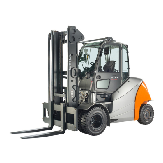
Foreword Your truck Your truck Description of the truck General The electrically driven counterbalanced trucks from series RX60–60/70/80 have a load ca- pacity of up to eight tonnes with a load centre of gravity of 900 mm. This means that the truck can reach a top speed of 17 km/h, which can be increased to 20 km/h thanks to sprint mode and PowerPlusLife battery. - Page 15 Foreword Your truck released. Completely removing your foot from the accelerator pedal causes the truck to brake until it comes to a standstill. A parking brake ensures that the truck remains securely in place when parked. Steering The truck is equipped with a swing axle and has kickback-free, hydraulic rear-wheel steer- ing.
-
Page 16: General
Foreword Your truck Operating devices The truck is characterised by an accessible operating concept. When purchasing the truck, a variety of operating devices and equipment variants are available: Double mini-lever ● Triple mini-lever ● Quadruple mini-lever ● Joystick 4Plus ● Fingertip switch ●... -
Page 17: Conformity Marking
Foreword Your truck The truck has been fitted with state-of-the-art technology. Following these operating instruc- tions will allow the truck to be handled safely. By complying with the specifications in these operating instructions, the functionality and the approved features of the truck will be retained. Get to know the technology, understand it and use it safely - these operating instructions pro- vide the necessary information and help to... -
Page 18: Declaration That Reflects The Content Of The Declaration Of Conformity
Foreword Your truck Declaration that reflects the content of the declaration of conformity Declaration STILL GmbH Berzeliusstraße 10 22113 Hamburg Germany We declare that the specified machine conforms to the most recent valid version of the direc- tives specified below:... -
Page 19: Accessories
Foreword Your truck Accessories Key for key switch (two pieces) ● Key for cab (variant) ● Hexagon socket wrench for emergency low- ● ering 56358042501 EN - - 11... -
Page 20: Overview
Foreword Your truck Overview 56358042501 EN - - 11... - Page 21 1430 1500 1500 3430 3430 1210 1210 1330 1330 1470 1470 1500 1500 800 700 DANGER DANGER STILL GmbH Hamburg Regelmäßige Prüfung (FEM 4.004) BATTERIESERVICE nach nationalen Vorschriften DANGER basierend auf den EG-Richtlinien: Nächste Prüfung 2009/104/EG, 99/92/EG Nächste Prüfung DANGER Ihr STILL Service Die Prüfplakette ersetzt nicht das Prüfprotokoll...
- Page 22 Foreword Your truck Decal information: Caution/Read the operat- Decal information: StVZO (German Road ing instructions/Fasten seat belt/Apply park- Traffic Licensing Regulations) information ing brake when leaving the truck/Passen- (variant) gers are not allowed/Do not jump off if the Decal information: Nameplate truck is tipping over/Lean in the opposite di- Decal information: Inspection sticker rection to which the truck is tipping...
- Page 23 Foreword Your truck Labelling points, right DANGER DANGER 10 bar DANGER 56358042501 EN - - 11...
-
Page 24: Nameplate
Foreword Your truck Decal information: Parking brake released Decal information: 12-V socket Decal information: Parking brake applied Warning sign: Risk of short circuit due to Decal information: Lifting gear attachment shearing point Warning sign: Danger due to shearing Manufacturer's label text Decal information: Tyre filling pressure Decal information: Caution/read the operat- Decal information: To unlock, turn 90°... -
Page 25: Production Number
Foreword Your truck Variant 2: Industrial trucks built after 12/2021 Nameplate Manufacturer Model/serial number/year of manufacture Tare weight Industrial truck / Chariot de manutation / Flurförderzeug Max. battery weight/min. battery weight (only for electric trucks) Ballast weight (only for electric trucks) Placeholder for "data matrix code"... -
Page 26: Stvzo (Road Traffic Licensing Regulations) Information
Capacity equivalent: Weight: CE labelling P/N: B-P/N: Safety information Custumer order no.: Still order no.: Data/technical data Date: Made in Germany Address of manufacturer Safety Advices for Lithium-Ion Batteries Do not crush. Do not heat or incinerate. Do not short-circuit. Do not dismantle. - Page 27 Foreword Your truck Variant 1: Industrial trucks built after 12/2021 Manufacturer Technology Transportation notes General operating notes CE labelling Data matrix code for the authorised serv- ice centre UKCA labelling Safety information Data/technical data Address of manufacturer 56358042501 EN - - 11...
-
Page 28: Using The Truck
Foreword Using the truck Using the truck Commissioning Commissioning is the initial intended use of the truck. The necessary steps for the commissioning vary depending on the model and equipment of the truck. These steps require preparatory work and adjustment work that cannot be per- formed by the operating company. -
Page 29: Improper Use
Foreword Using the truck The regulations regarding trailer operation must be observed; see chapter "Trailer operation". Improper use The operating company or driver, and not the manufacturer, is liable for any hazards caused by improper use. NOTE Please note the definition of the following re- sponsible persons: "operating company"... -
Page 30: Parking In Temperatures Below -10 °C
Foreword Using the truck Driving on upward and downward gradients is permitted provided the specified data and specifications are observed, see the "Routes "chapter. The truck is suitable for indoor and outdoor use in countries ranging from the Tropics to Nordic regions (temperature range: -20 °C to +40 °C). -
Page 31: Using Working Platforms
Foreword Using the truck Using working platforms WARNING The use of working platforms is regulated by national law. The use of working platforms is only permitted by virtue of the jurisdiction in the country of use. – Observe national legislation. –... -
Page 32: Information About The Documentation
Foreword Information about the documentation Information about the documentation Documentation scope Original operating instructions ● Original operating instructions for attach- ● ments (variant) Spare parts list ● Depending on the truck equipment, "UPA" ● operating instructions may also be provided NOTE Refer to the additional information in the sec- tion entitled "Rules for the operating company... -
Page 33: Supplementary Documentation
Foreword Information about the documentation The operating company must ensure that all users have received, read and understood these operating instructions. Safely store the complete documentation and pass on to the subsequent operating company when transferring or selling the truck. NOTE Please observe the definition of the following responsible persons: "operating company"... -
Page 34: Issue Date And Topicality Of The Operating Instructions
The issue date and the version of these oper- ating instructions can be found on the title page. STILL is constantly engaged in the further de- velopment of trucks. These operating instruc- tions are subject to change, and any claims based on the information and/or illustrations contained in them cannot be asserted. -
Page 35: List Of Abbreviations
Foreword Information about the documentation ENVIRONMENT NOTE To prevent environmental damage. List of abbreviations This list of abbreviations applies to all types of operating instructions. Not all of the abbrevia- tions that are listed here will necessarily ap- pear in these operating instructions. Abbrevi- Meaning Explanation... - Page 36 Foreword Information about the documentation Abbrevi- Meaning Explanation ation International Organization for Standardi- International standardisation organisation zation Uncertainty of measurement of sound pressure levels Local Area Network Local area network Light Emitting Diode Light emitting diode Sound pressure level at the workplace Average continuous sound pressure level in the driver's compartment Distance of the centre of gravity of the...
-
Page 37: Units
Foreword Information about the documentation Units Unit symbol Unit name Explanation °C Degree Celsius Unit of temperature °F Degree Fahrenheit Unit of temperature Ampere Unit of electrical current Unit of electrical charge storage capacity (nominal Ampere hour capacity) Decibel Unit of sound intensity Centimetre Unit of length (1 cm = 10 mm) Cubic centimetres... -
Page 38: Definition Of Directions
Foreword Information about the documentation Unit symbol Unit name Explanation Tonne Unit of mass (1 t = 1000 kg) Volt Unit of electrical voltage Watt Unit of electrical power W/kg Watt/kilogram Performance by mass (power density) Watt-hours Unit of electrical work (nominal energy) Wh/kg Watt-hours/kilogram Stored energy per kilogram of mass (energy density) -
Page 39: Schematic Views
Foreword Information about the documentation Schematic views View of functions and operations This documentation explains the (usually se- quential) chain of certain functions or opera- tions. Schematic diagrams of a counterbal- ance truck are used to illustrate these proce- dures. -
Page 40: Environmental Considerations
Foreword Environmental considerations Environmental considerations Packaging During delivery of the truck, certain parts are packaged to provide protection during trans- port. This packaging must be removed com- pletely prior to initial start-up. ENVIRONMENT NOTE The packaging material must be disposed of properly after delivery of the truck. -
Page 41: Safety
Safety... -
Page 42: Definition Of Responsible Persons
Safety Definition of responsible persons Definition of responsible persons Operating company The operating company is the natural or legal person or group who operates the truck or on whose authority the truck is used. The operating company must ensure that the truck is only used for its proper purpose and in compliance with the safety regulations set out in these operating instructions. -
Page 43: Drivers
Safety Definition of responsible persons Drivers This truck may only be driven by suitable per- sons who are at least 18 years of age, have been trained in driving, have demonstrated their skills in driving and handling loads to the operating company or an authorised represen- tative, and have been specifically instructed to drive the truck. - Page 44 Safety Definition of responsible persons Prohibition of use by unauthorised per- sons The driver is responsible for the truck during working hours. He must not allow unauthor- ised persons to operate the truck. When leaving the truck, the driver must secure it against unauthorised use, e.g.
-
Page 45: Basic Principles For Safe Operation
Safety Basic principles for safe operation Basic principles for safe operation Insurance cover on company premises In many cases, company premises are restric- ted public traffic areas. NOTE The business liability insurance should be re- viewed to ensure that, in the event of any damage caused in restricted public traffic areas, there is insurance cover for the truck in respect of third parties. - Page 46 Safety Basic principles for safe operation – Contact the authorised service centre be- fore converting or retrofitting the truck. Only the authorised service centre is permitted to perform welding work on the truck. DANGER Risk of explosion from additional bores in the battery hood! Explosive gases can escape and can lead to potentially fatal injuries if they ex-...
-
Page 47: Changes To The Overhead Guard And Roof Loads
Safety Basic principles for safe operation The operating company must also fulfil the fol- lowing prerequisites: Design documents, test documents and as- ● sembly instructions associated with the modification must be permanently archived and remain accessible at all times. The capacity rating plate, the decal informa- ●... -
Page 48: Warning Regarding Non-Original Parts
STILL. CAUTION Installation and/or use of such products may there- fore have a negative impact on the design features of the truck and thus impair active and/or passive driv- ing safety. -
Page 49: Tyres
Safety Basic principles for safe operation Work on the electrical system (e.g. connecting a radio, additional headlights etc.) is only per- mitted with the manufacturer's written appro- val. All electrical system interventions must be documented. Even if they are removable, roof panels may not be removed, as they are designed to pro- tect against small falling objects. -
Page 50: Medical Equipment
Safety Basic principles for safe operation one side (e.g. always replace right-hand and left-hand wheels at the same time). Changes must only be made following consultation with the manufacturer. If the type of tyre used on an axle is changed, for example from superelastic tyres to pneu- matic tyres, the load diagram must be changed accordingly. -
Page 51: Exercise Caution When Handling Gas Springs And Accumulators
Safety Basic principles for safe operation Exercise caution when handling gas springs and accumulators WARNING Gas springs are under high pressure. Improper re- moval results in an elevated risk of injury. For ease of operation, various functions on the truck can be supported by gas springs. - Page 52 Safety Basic principles for safe operation picked up. These other loading units then fall over when the load is raised. – For help with selecting the correct fork arms, contact the authorised service centre. 56358042501 EN - - 11...
-
Page 53: Residual Risk
Safety Residual risk Residual risk Residual dangers, residual risks Despite careful working and compliance with standards and regulations, the occurrence of other risks when using the truck cannot be en- tirely excluded. The truck and all other system components comply with current safety requirements. Nev- ertheless, even when the truck is used for its proper purpose and all instructions are fol- lowed, some residual risk cannot be excluded. -
Page 54: Special Risks Associated With Using The Truck And Attachments
Safety Residual risk with these regulations either intentionally or carelessly. Stability The stability of the truck has been tested to the latest technological standards and is guar- anteed provided that the truck is used properly and according to its intended purpose. These standards only take into account the dynamic and static tipping forces that can arise during specified use in accordance with the operating... - Page 55 Safety Residual risk the truck correctly and without the risk of acci- dents. 56358042501 EN - - 11...
-
Page 56: Overview Of Hazards And Countermeasures
Safety Residual risk Overview of hazards and countermeasures NOTE This table is intended to help evaluate the hazards in your facility and applies to all drive types. It does not claim to be complete. – Observe the national regulations for the country in which the truck is being used. - Page 57 Safety Residual risk Hazard Course of action Check note Notes √ done - Not applicable Assessment of LPG German threshold limit exhaust gases values list (MAK-Liste) and the German Ordi- nance on Industrial Safety and Health (BetrSichV) Impermissible usage Provide operating in- German Ordinance on (improper usage) structions...
-
Page 58: Danger To Employees
Safety Residual risk Hazard Course of action Check note Notes √ done - Not applicable DGUV rule 113-001 and observe the oper- ating instructions When parking LPG German Ordinance on German Ordinance on trucks Industrial Safety and Industrial Safety and Health (BetrSichV), Health (BetrSichV) and DGUV rule 113-001... - Page 59 Safety Residual risk NOTE Please note the definition of the following re- sponsible persons: "operating company" and "driver". The design and equipment of the truck comply with the standards and directives required for CE conformity. The design and equipment al- so comply with the standards and directives necessary for the UKCA compliance that is re- quired in the United Kingdom.
-
Page 60: Safety Tests
Safety Safety tests Safety tests Regular safety inspection of the truck Safety inspection based on time and ex- traordinary incidents The operating company must ensure that the truck is checked by a specialist at least once a year or after particular incidents. As part of this inspection, a complete check of the technical condition of the truck must be performed with regard to accident safety. - Page 61 Safety Safety tests The insulation testing results must be at least the test values given in the following two tables. – For insulation testing, contact the author- ised service centre. The exact procedure for this insulation testing is described in the workshop manual for this truck.
-
Page 62: Safety Regulations For Handling Consumables
Safety Safety regulations for handling consumables Safety regulations for handling consumables Permissible consumables WARNING Consumables can be dangerous! – Observe general information and safety informa- tion regarding the use of consumables. – Refer to the chapter entitled "Safety regula- tions for handling consumables". –... -
Page 63: Hydraulic Fluid
Safety Safety regulations for handling consumables WARNING Prolonged intensive contact with the skin can result in dryness and irritate the skin! – Avoid contact and consumption. – Wear protective gloves. – After any contact, wash the skin with soap and water, and then apply a skin care product. -
Page 64: Battery Acid
Safety Safety regulations for handling consumables WARNING These fluids are pressurised during op- eration of the truck and are hazardous to your health. – Do not allow the fluids to come into contact with the skin. – Avoid inhaling spray. –... -
Page 65: Coolant And Cooling Fluid
Safety Safety regulations for handling consumables WARNING Battery acid contains dissolved sulphuric acid. This is corrosive. – When working with battery acid, use appropriate PSA (rubber gloves, apron, protection goggles). – When working with battery acid, nev- er wear a watch or jewellery. –... -
Page 66: Disposal Of Consumables
Safety Safety regulations for handling consumables – Soak up any spilt coolant or cooling fluid im- mediately using an oil binding agent and dispose of it in accordance with the national regulations for the country of use. – Dispose of old coolant or cooling fluid in ac- cordance with the national regulations for the country of use. -
Page 67: Emissions
Safety Emissions Emissions The values specified apply to a standard truck (compare the specifications in the "Technical data" chapter). Different tyres, lift masts, addi- tional units etc. may produce different values. Noise emissions The values were determined based on meas- uring procedures from the standard EN 12053 "Safety of industrial trucks - Test methods for measuring noise emissions", based on... - Page 68 Safety Emissions Vibrations The vibrations of the machine have been de- termined on an identical machine in accord- ance with the standards DIN EN 13059 "Safe- ty of industrial trucks - Test methods for meas- uring vibration" and DIN EN 12096 "Mechani- cal vibration - Declaration and verification of vibration emission values".
- Page 69 – Observe the safety regulations for handling the battery. Radiation In accordance with the guidelines DIN EN 62471:2009-03 (VDE 0837-471:2009-03), the STILL Safety- Light (variant) is assigned to risk group 2 (me- dium risk) due to its photobiological hazard potential. 56358042501 EN - - 11...
- Page 70 Safety Emissions 56358042501 EN - - 11...
-
Page 71: Overviews
Overviews... -
Page 72: Overview
Overviews Overview Overview Left-hand side (when viewed in the drive direction) 6341_003-019_V2 Lift mast Drive axle Driver's compartment Tilt cylinder Overhead guard Fork arms Left side cover Fork carriage Steering axle Lift cylinder 56358042501 EN - - 11... - Page 73 Overviews Overview Right-hand side (when viewed in the drive direction) Fresh air filter for heating system Coupling pin Cover, front right Rear cover Battery cover 56358042501 EN - - 11...
-
Page 74: Driver's Compartment
Overviews Driver's compartment Driver's compartment Parking brake lever Bottle holder for bottles of max. 0.5 l Steering wheel Driver's seat Key switch Storage compartment / storage compart- Display and operating unit ment with cover (variant) Document holder / storage compartment for Compartment operating instructions Filler cap for windscreen washer reservoir... -
Page 75: Operating Devices And Display Elements
Overviews Operating devices and display elements Operating devices and display elements Display operating unit Hazard warning system button Reverse travel display Front windscreen wiper button Power rating display Working spotlight button Time display (digital) Drive programme selector button Not assigned Softkey for lighting Rotating beacon display Lighting symbol... -
Page 76: Operating Devices For Hydraulic And Driving Functions
Overviews Operating devices and display elements – If you have any questions, please contact your authorised service centre. Operating devices for hydraulic and driving functions Different versions of the operating devices are available for operating the truck's hydraulic functions and drive functions. The truck can be equipped with the following operating devices: Double mini-lever... -
Page 77: Double Mini-Lever
Overviews Operating devices and display elements Double mini-lever 7312_003-002 "Lift mast" 360° lever Function key "5th function" Function key F1 "Attachments" cross lever Function key F2 Emergency stop switch "Drive direction / turn indicator" cross lever Signal horn button NOTE Depending on the specification, various elec- tric attachment parts can be controlled via function keys (2) and (3). -
Page 78: Three-Way Mini-Lever
Overviews Operating devices and display elements Three-way mini-lever 5060_003-089 "Lift mast" 360° lever "Auxiliary hydraulics 1" operating lever Function key F1 "Auxiliary hydraulics 2" operating lever Function key F2 Emergency stop switch "Drive direction / turn indicator" cross lever Signal horn button Function key "5th function"... -
Page 79: Four-Way Mini-Lever
Overviews Operating devices and display elements Four-way mini-lever 5060_003-088 "Lift/lower" operating lever Function key "5th function" "Tilt" operating lever "Auxiliary hydraulics 1" operating lever Function key F1 "Auxiliary hydraulics 2" operating lever Function key F2 Emergency stop switch "Drive direction / turn indicator" cross lever Signal horn button NOTE Depending on the specification, various elec-... -
Page 80: Joystick 4Plus
Overviews Operating devices and display elements Joystick 4Plus 6210_003-087 Horizontal rocker button for the "3rd hydraul- LED for the clamp locking mechanism (var- ic function", tilting the lift mast iant) Symbols for the basic hydraulic functions Slider for the "4th hydraulic function", e.g. Pictograms for the 5th hydraulic function and side shift frame forwards/backwards for the clamp locking mechanism (variant) -
Page 81: Fingertip
Overviews Operating devices and display elements Fingertip 6321_003-004 Function key F1 Emergency stop switch Function key F2 "Attachments" operating lever Left-hand turn indicator button "Attachments" operating lever Signal horn button "Tilt" operating lever Right-hand turn indicator button "Lift/lower" operating lever Button for 5th function Travel direction switch NOTE... -
Page 82: Mini Console
Overviews Operating devices and display elements Mini console The mini console is located on the steering column below the steering wheel. 7311_003-056 Travel direction switch Direction indicator switch 56358042501 EN - - 11... -
Page 83: Operating
Operating... -
Page 84: Checks And Tasks Before Daily Use
Operating Checks and tasks before daily use Checks and tasks before daily use Visual inspections WARNING Risk of injury from falling off the truck! When climbing onto the truck, there is a risk of getting stuck or slipping and fall- ing. - Page 85 Operating Checks and tasks before daily use Component Course of action Ensure the attachments are mounted correctly in accordance with the operating instructions of the manufacturer. Attachments (variant) Perform a visual inspection to ensure the attach- ments are intact and not leaking. Perform checks to ensure the attachments are working correctly.
- Page 86 Operating Checks and tasks before daily use Component Course of action Perform a visual inspection for deformation and wear (for example, bent, torn, broken). Check the securing bush in the counterweight for Coupling pin, tow coupling (variant) integrity and to ensure that it is working correctly. Check that the linchpin is present and working cor- rectly (chain, rope, split pin).
-
Page 87: Climbing Into And Out Of The Truck
Operating Checks and tasks before daily use Climbing into and out of the truck WARNING Risk of injury when climbing into and out of the truck due to slipping, striking parts of the truck or becom- ing stuck! If the footwell cover is very dirty or smeared with oil, there is a risk of slipping. - Page 88 Operating Checks and tasks before daily use Climbing in and out of trucks featuring a single wheel and two steps When climbing into and out of the truck, use the handles (2) and (4) for support. The over- head guard post (1) can also be used for sup- port.
- Page 89 Operating Checks and tasks before daily use Climbing in and out of trucks featuring two wheels and three steps When climbing into and out of the truck, use the handles (2) and (4) for support. The over- head guard post (1) can also be used for sup- port.
-
Page 90: Shelves And Cup Holders
Operating Checks and tasks before daily use Shelves and cup holders WARNING Risk of accident! Objects that fall into the footwell during travel as a re- sult of steering or braking may slip between the ped- als (3) and prevent them from working correctly. It may then be impossible to brake the truck. - Page 91 Operating Checks and tasks before daily use WARNING To obtain optimum seat cushioning, you must adjust the seat suspension to your own body weight. This course of action is better for your back and protects your health. – To prevent injury, make sure that there are no ob- jects within the swivel area of the seat.
- Page 92 Operating Checks and tasks before daily use Adjusting the seat suspension NOTE The driver's seat can be adjusted to suit the weight of the individual driver. To obtain opti- mal settings for the seat suspension, the driv- er must perform the adjustment whilst sitting on the seat.
- Page 93 Operating Checks and tasks before daily use Adjusting the lumbar support (variant) NOTE The lumbar support can be adjusted to suit the contours of the individual driver's spine. Ad- justing the lumbar support moves a convex support cushion into the upper or lower part of the backrest.
- Page 94 Operating Checks and tasks before daily use Switching the seat heater (variant) on and off NOTE The seat heater functions only if the seat con- tact switch is active, i.e. when the driver is sit- ting on the driver's seat. –...
-
Page 95: Adjusting The Armrest
Operating Checks and tasks before daily use Blocking the longitudinal horizontal sus- pension – If necessary, the longitudinal horizontal sus- pension can be blocked using the locking lever (2) on the left-hand side of the driver's seat as viewed in the drive direction: Longitudinal horizontal suspension free Longitudinal horizontal suspension blocked... -
Page 96: Adjusting The Steering Column
Operating Checks and tasks before daily use Adjusting the length of the armrest – Release the star-grip handle (1) by turning it anti-clockwise. – Shift the armrest (2) into the desired posi- tion. – Tighten the star-grip handle by turning it clockwise. -
Page 97: Unlocking The Emergency Off Switch
Operating Checks and tasks before daily use Unlocking the emergency off switch – Pull the emergency off switch (1) until it is unlocked. 7312_003-183 Operating the signal horn NOTE The signal horn is used to warn people against imminent danger or to announce your intention to overtake. -
Page 98: Seat Belt
Operating Checks and tasks before daily use Seat belt DANGER Even when using an approved restraint system, there is some residual risk of the driver being injured if the truck tips over. This risk of injury can be reduced through the combined use of the re- straint system and the seat belt. - Page 99 Operating Checks and tasks before daily use NOTE The buckle has a buckle switch (variant). In the event of an operating error or malfunction, the message SAFETY BELT appears in the display and operating unit, see the chapter en- titled "Display messages". –...
- Page 100 Operating Checks and tasks before daily use Releasing the seat belt – Push the red button (4) on the buckle (1). – Slowly guide the belt tongue back to the re- tractor by hand. NOTE Do not allow the seat belt to retract too quick- ly.
-
Page 101: Using The Driver's Cab
Operating Checks and tasks before daily use Using the driver's cab DANGER Risk of fatal injury in the event of falling from the truck if it tips over! In order to prevent the driver from sliding underneath the truck and being crushed if the truck tips over, a restraint system must be in place and must be used. -
Page 102: Checking The Brake System For Correct Function
Operating Checks and tasks before daily use Checking the brake system for correct function DANGER Risk of accident in the event of failure of the brake system! If the brake system fails, the truck will be insufficient- ly braked. – Do not operate the truck if the brake system is faulty. - Page 103 Operating Checks and tasks before daily use – Accelerate the unladen truck in a clear area. – Press the brake pedal (1) firmly. The truck must decelerate noticeably. Checking the parking brake on a gradi- ent or a lorry ramp DANGER Risk to life if the truck rolls away! If the parking brake is not applied, the...
- Page 104 Operating Checks and tasks before daily use NOTE When the emergency off switch is actuated, note the following: The electric brake is disabled. The truck no ● longer responds to the command issued by the accelerator pedal. The power steering is no longer available. ●...
-
Page 105: Checking The Steering System For Correct Function
Operating Checks and tasks before daily use Checking the steering system for correct function DANGER If the hydraulics fail, there is a risk of accident as the steering characteristics have changed. – Do not operate the truck if it has a defective steer- ing system. -
Page 106: Checking The Vertical Lift Mast Position (Variant) For Correct Function
Operating Checks and tasks before daily use – Press the emergency off switch (1). The truck will roll to a stop. – Brake the truck to a standstill by depressing the brake pedal. – Pull out the emergency off switch (1). The knob is unlocked and pops out. -
Page 107: Zero Adjustment Of The Load Measurement (Variant)
Operating Checks and tasks before daily use – Release the operating device to tilt and ac- tuate again. The lift mast must tilt forwards fully and move gently as far as the end stop. Zero adjustment of the load measurement (variant) NOTE A zero adjustment must be carried out in order to guarantee the accuracy of the load meas-... - Page 108 Operating Checks and tasks before daily use – Press the Softkey (1). The zero adjustment of the load measurement is switched on. The symbol is displayed. The message appears on the LOWER FORKS display. NOTE During the following process, the fork carriage must be lowered slightly and then stopped abruptly.
-
Page 109: Switching On
Operating Switching on Switching on Switching on the key switch WARNING Before switching on the key switch, all tests and op- erations prior to commissioning must be performed without any defects being detected. – Carry out checks and operations before commis- sioning. - Page 110 Operating Switching on This initiates a self-test. All lamps in the drive direction and turn indicator displays light up briefly. 7312_003-085 When the key switch is switched on, the dis- play shows the welcome screen in the set lan- guage until the truck controller has fully star- ted up.
-
Page 111: Access Authorisation With Pin Code (Variant)
Operating Switching on Standard display elements Battery charge The available battery capacity is shown in the display field. Drive program The current traction program (1–5) ap- pears on the display. Power rating The average power consumption and consumption trends are shown in the dis- play field. - Page 112 PIN is only known to per- sons with corresponding access authorisation. The driver PINs are stored in the truck control unit. These are still available if the display and operating unit has been changed. The author- ised service centre can use a diagnostic de- vice to read out the driver PIN and, if necessa- ry, restore the factory default driver PIN.
- Page 113 Operating Switching on ACCESS CODE input menu The driver enters the five-digit driver PIN (00000 to 99999) in this input menu. The driver PIN is entered using the buttons or Softkeys (1). The digits entered for the driver PIN (2) are not visible but are represented by circles instead.
- Page 114 Operating Switching on After three invalid entry attempts, the mes- sage appears. The input is CODE DENIED then locked for five minutes before another at- tempt can be made. BQ_024_en_V2 Defining the driver PIN NOTE The driver PINs can be defined only by per- sons with the appropriate access authorisa- tion, e.g.
- Page 115 Operating Switching on appears in the display. PASSWORD – Enter the four-digit password (factory de- fault: 2777) using the buttons (1). – Confirm the input using Softkey (2). BQ_030_en_V2 appears in the display. CONFIGURATION – Use the drive program selection button (1) and the menu change button (3) to select menu.
- Page 116 Operating Switching on Selecting the driver PIN In the menu, there are fifty ACCESS CODE possible driver PINs to choose from. The digit sequences can be set or changed in submenu. NEW CODE Once the menu has been ac- ACCESS CODE cessed, the selection field (2) contains...
- Page 117 Operating Switching on appears in the display. CONFIRM submenu is used to confirm CONFIRM the new driver PIN. – Enter the new driver PIN for a second time in the field (8) using the buttons CONFIRM or Softkeys (7). If the entry matches the new driver PIN previ- ously entered, the system will accept the new driver PIN once the last digit has been en-...
- Page 118 Operating Switching on After three incorrect entries, the CODE DE- message appears. NIED The display switches back to the ACCESS menu. The desired driver PIN must be CODE re-defined. BQ_024_en_V2 Changing the password It is recommended that you change the factory default password.
- Page 119 Operating Switching on appears in the display. PASSWORD – Enter the current password using the but- tons (1). – Confirm the input using Softkey (2). BQ_030_en_V2 appears in the display. CONFIGURATION – Use the drive program selection button (1) and the menu change button (3) to select menu.
- Page 120 Operating Switching on appears in PASSWORD/PASSWORD LEVEL the display. – Use the drive program selection button (1) and the menu change button (4) to select the desired (2). PASSWORD LEVEL – Confirm your selection using Soft- (3). BQ_033_en appears in the display. ...
- Page 121 Operating Switching on – To exit the configuration menu, press Soft- (2) repeatedly until the standard display appears. 56358042501 EN - - 11...
-
Page 122: Operating The Display-Operating Unit
Operating Operating the display-operating unit Operating the display-operating unit Indicators Standard displays In the factory setting, the following indicators can be seen in the display and operating unit: Battery charge Displays the available battery capacity as a segmented bar graph in 10% incre- ments. - Page 123 Operating Operating the display-operating unit CAUTION Deep discharges shorten the service life of the bat- tery. If no bar is shown (0% of the available battery ca- pacity, i.e. around 20% of the nominal capacity), deep discharge begins. – Deep discharge (no bar on the display) must be avoided.
-
Page 124: Adjusting The Displays
Operating Operating the display-operating unit Displays the total distance driven in kilome- tres. Daily kilometres ● Displays the kilometres driven for the day. NOTE Ask the authorised service centre about the speed driven indicator. NOTE Have all repair and maintenance work per- formed by an authorised service centre. - Page 125 Operating Operating the display-operating unit – Press the drive program button (1) and the menu change button (2) at the same time. Blue-Q_029_V2 The display changes to the menu. PASSWORD NOTE It may be necessary to enter a password in or- der to configure the displays.
-
Page 126: Symbols In The Display
Operating Operating the display-operating unit – Press the Softkey (3). The display changes to the CONFIGURA- menu. TION The following settings are possible and can be found in the corresponding chapter: Setting the date and time ● Resetting the daily kilometres and daily op- ●... - Page 127 Operating Operating the display-operating unit Description Symbol Hydraulic system Exh.gas purifier Coolant temperature Fuel level Blue-Q Power rating (average) Power rating (trend) Symbols for warning messages Description Symbol Parking brake Actuate seat switch Safety belt Battery acid level Neutral warning message Are you sure? Oil pressure Symbols for error messages...
- Page 128 Operating Operating the display-operating unit Description Symbol Rear working spotlight ON Front working spotlight OFF Front working spotlight ON Windscreen heating OFF Windscreen heating ON Rear window heating OFF Rear window heating ON Interior lighting OFF Interior lighting ON Roof wiper/washer OFF Roof wiper/washer ON Heater blower OFF Heater blower ON...
- Page 129 Operating Operating the display-operating unit Description Symbol Confirm information Reset Back by one menu level Back to the previous edit field Scroll up Scroll down Count up Count down Status LEDs of the function keys for ad- ditional electrical installations The current switch status of a button is indica- ted with LEDs next to the relevant function key for the additional electrical installation.
-
Page 130: Setting The Date Or Time
Operating Operating the display-operating unit Screen for entering the driver PIN (access code): BQ_038 Setting the date or time – Switch to the menu; see CONFIGURATION the chapter entitled "Adjusting the displays". – Press the Drive programme button (1) or the Menu change button (2) repeatedly until option appears. -
Page 131: Resetting The Daily Kilometres And Daily Operating Hours
Operating Operating the display-operating unit Resetting the daily kilometres 1 2 3 4 and daily operating hours The daily number of kilometres and daily oper- ating hours displays can be reset to zero: – Switch to the menu; see CONFIGURATION the chapter entitled "Adjusting the displays". -
Page 132: Softkeys For Operating Various Equipment Variants
Operating Operating the display-operating unit Softkeys for operating various equipment variants Additional functions can be displayed on the display-operating unit. These additional func- tions, e.g. a rotating beacon, can be switched on and off using Softkeys. Changing the Softkey functions: ... - Page 133 Operating Operating the display-operating unit STANDARD Blue-Q is turned off whenever the truck is ● commissioned. The driver can use the Blue- Q button to switch efficiency mode on and off at any time while the truck is being oper- ated FIXED Blue-Q is switched on permanently whenev-...
-
Page 134: Blue-Q Efficiency Mode
Operating Blue-Q efficiency mode Blue-Q efficiency mode Functional description The Blue-Q efficiency mode affects both the drive unit and the activation of the additional consumers, and reduces the truck's energy consumption. If the efficiency mode has been activated, the acceleration behaviour of the truck changes to make acceleration more moderate. -
Page 135: Switching Off Additional Consumers
Operating Blue-Q efficiency mode Switching off additional consumers If the Blue-Q efficiency mode is activated, the controller switches off various additional con- sumers after a few seconds in certain condi- tions. The additional consumers available de- pend on the truck equipment. The following ta- ble shows the conditions that cause additional consumers to be switched off. -
Page 136: Switching Efficiency Mode Blue-Q On And Off
Operating Blue-Q efficiency mode Switching efficiency mode Blue- Q on and off NOTE The Blue-Q efficiency mode can be switched on and off in the STANDARD and FIXED- FLEX operating modes. If the FIXED operat- ing mode is configured in the display-operat- ing unit, the Blue-Q button is disabled and the Blue-Q efficiency mode is switched on perma- nently. -
Page 137: Driving
Operating Driving Driving Safety regulations when driving Driving conduct The driver must follow the public rules of the road when driving in company traffic. The speed must be appropriate to the local conditions. For example, the driver must drive slowly around corners, in tight passageways, when driving through swing-doors, at blind spots, or on uneven surfaces. - Page 138 There is a risk of acci- dent! – Do not use devices during travel or when handling loads. – Set the volume so that warning signals can still be heard. WARNING In areas where use of mobile phones is prohibited, use of a mobile phone or radio telephone is not per- mitted.
-
Page 139: Roadways
The required aisle widths depend on the di- mensions of the load. For pallets, these are: Aisle width [mm] With pallet With pallet Model Type 1000x1200 800x1200 crosswise lengthwise RX60-60 6341 RX60-70 6342 4907 5107 RX60-80 6343 RX60–80 6344 4999 5199... - Page 140 Operating Driving It is permitted to drive the truck on the follow- ing ascending and descending gradients: Maximum gradient [%] Model Type With a load Without a load RX60-60 6341 16.3 25.0 (LSP 600) RX60-70 6342 15.5 25.3 (LSP 600)
-
Page 141: Setting The Drive Programme
Operating Driving Condition of the roadways Roadways must be firm, level and free from contamination and fallen objects. The structural design of drains, level crossings and other similar facilities must enable them to be driven over with as few bumps as possible. If necessary, use ramps to compensate for un- even roadways. - Page 142 Operating Driving – Push the drive programme button (1) re- peatedly until the number of the desired drive programme appears on the display (2). Drive programs 1–5 are available. Essentially, the higher the drive program num- ber is, the greater the driving dynamics. 6311_003-028_V2 The following drive programmes are available: Drive values...
-
Page 143: Sprint Mode (Variant)
Operating Driving Sprint mode (variant) NOTE Sprint mode is only possible in combination with the PowerPlusLife battery. Switching on sprint mode The performance of the electric drive can be increased by switching on sprint mode. When sprint mode is on, the truck accelerates to maximum speed more quickly. -
Page 144: Selecting The Drive Direction
Operating Driving Selecting the drive direction The drive direction of the truck must be selec- ted using the drive direction switch before at- tempting to drive. The method of actuating the drive direction switch depends on the operat- ing devices included in the truck's equipment. Possible equipment variants include: Mini-lever ●... -
Page 145: Actuating The Drive Direction Switch, Mini-Lever Version
Operating Driving Actuating the drive direction switch, mini-lever version – Push the cross lever (1) forwards to drive "forward". – Pull the cross lever backwards to drive "backward". 5060_003-096 Actuating the vertical rocker but- ton for the "drive direction", Joy- stick 4Plus version –... -
Page 146: Actuate The Drive Direction Switch, Fingertip Version
Operating Driving Actuate the drive direction switch, fingertip version – For the "forwards" drive direction, push the drive direction switch (1) forwards. – For the "backwards" drive direction, push the drive direction switch backwards. 5060_003-097 Actuating the drive direction ... - Page 147 Operating Driving The driver's seat has a seat switch that checks whether the driver's seat is occupied. The truck cannot be moved if the driver's seat is not occupied or if the seat switch malfunc- tions. All lifting functions are disabled. The message appears on the dis- SEAT SWITCH play-operating unit.
- Page 148 Operating Driving NOTE If the following message appears in the dis- play when the accelerator pedal is actu- ated: ! PARKING BRAKE OIL PRESSURE , the service brake of the truck is not yet ready for operation. The driving speed is limited to 5 km/h. ●...
-
Page 149: Starting Drive Mode, Dual Pedal Version (Variant)
If the truck still cannot be operat- ed, park the truck securely and contact the authorised service centre. - Page 150 Operating Driving – Actuate the right-hand accelerator pedal (1) to drive "forward" and actuate the left-hand accelerator pedal (2) to drive "backward". NOTE In the dual pedal version, the drive direction switches on the operating devices do not func- tion.
- Page 151 If the truck still cannot be operat- ed, park the truck securely and contact the au- thorised service centre.
-
Page 152: Operating The Service Brake
Operating Driving Operating the service brake The regenerative brake converts the accelera- tion energy of the truck into electrical energy. This causes the truck to brake. – To do this, release the accelerator ped- al (1). – If the braking effect is inadequate, use the brake pedal (2) to also actuate the service brake. -
Page 153: Actuating The Mechanical Parking Brake
Operating Driving Actuating the mechanical park- ing brake DANGER There is a risk of being run over if the truck rolls away, and therefore a danger to life. – The truck must not be parked on a slope. – In emergencies, secure with wedges on the side facing downhill. - Page 154 Operating Driving Releasing the parking brake – Pull the parking brake lever (1) down fully out of the middle position. – In the lower lever position, pull out the lever knob and then guide the parking brake lever up fully. NOTE The parking brake lever swivels to the upper position automatically by means of spring...
-
Page 155: Steering
Operating Driving Steering DANGER If the hydraulics fail, there is a risk of accident as the steering characteristics have changed. – Do not operate the truck if it has a defective steer- ing system. – Steer the truck by turning the steering wheel (1) accordingly. -
Page 156: Reducing Speed When Turning (Curve Speed Control)
DANGER The Curve Speed Control function cannot override the physical limits of stability. Despite this function, there still is a risk of tipping! – Before using this function, familiarise yourself with the change to the driving and steering characteris- tics of the truck. -
Page 157: Driving On Ascending And Descending Gradients
Operating Driving Driving on ascending and de- scending gradients DANGER Danger to life! Driving on ascending and descending gradients car- ries special dangers! – Always follow the instructions below. – On ascending and descending gradients, the load must be carried facing uphill. –... -
Page 158: Reducing Speed With A Raised Load (Variant)
Operating Driving Reducing speed with a raised load (variant) This function (variant) reduces the speed of the truck with a raised load. 7321_003-052_en_V2 56358042501 EN - - 11... -
Page 159: Parking
Operating Parking Parking Parking the truck securely and switching it off DANGER Risk of fatal injury from being run over if the truck rolls away! – The truck must not be parked on a slope. – In emergencies, secure with wedges on the side facing downhill. -
Page 160: Wheel Chock (Variant)
Operating Parking NOTE Switch keys, FleetManager cards (variant), FleetManager transponder chips (variant) and the PIN code for access authorisation (variant) must not be handed over to other persons un- less explicit instructions to this effect have been given. Wheel chock (variant) ... -
Page 161: Lifting
Operating Lifting Lifting Lifting system variants The movement of the fork carriage and the lift mast heavily depends on the following equip- ment: The lift mast with which the truck is equip- ● ped, see C hapter "Types of lift mast", ⇒ ... -
Page 162: Lift Mast Vertical Position (Variant)
Operating Lifting Overriding and reactivating the auto- matic lift cut out If a load needs to be lifted to the truck's maxi- mum lift height and the automatic lift cut out function is not required, it is possible to over- ride the lift cut out. - Page 163 Operating Lifting CAUTION Risk of damage to property due to the lift mast collid- ing with racks or other objects! – Before using the "lift mast vertical position" com- fort feature, position the truck at a sufficient dis- tance from racks and other objects. The "lift mast vertical position"...
- Page 164 Operating Lifting Automatic approach towards the "lift mast vertical position" – Switch on the "lift mast vertical position" comfort feature via the button (1) on the dis- play and operating unit. – Tilt the lift mast forwards using the corre- sponding operating device.
- Page 165 Operating Lifting The lift mast is tilted forwards and stops as soon as the vertical position is reached. The arrow above the bar shown on the screen of the display and operating unit represents the "lift mast vertical position". Tilt the lift mast forwards beyond the vertical position: –...
-
Page 166: Types Of Lift Mast
Operating Lifting Calibrating the "lift mast vertical posi- tion" – Set the lift mast to the required position. – Press and hold the button (1) for the "lift mast vertical position" for at least five sec- onds. The message " "... -
Page 167: Malfunctions During Lifting Mode
Operating Lifting Triplex lift mast (variant) During lifting, the inner lift cylinder moves up to free lift (3), and then the outer lift cylinders raise the inner lift mast up to the max. height (2). DANGER Risk of accident due to collision of the lift mast or load with low ceilings or entrances. -
Page 168: Hydraulic Blocking Function
Operating Lifting Load chains not under tension DANGER Danger caused by a falling load! – Make sure that the chain(s) does (do) not become slack when lowering the load. Slack chains can, for instance, result from: Resting the fork carriage or the load on the ●... -
Page 169: Lifting System Operating Devices
Operating Lifting – Sit down on the driver's seat. All the relevant functions of the working hy- draulics will be available again. NOTE If it is not possible to release the block on the hydraulics when the load is raised because of a technical fault, the load must be lowered us- ing the "emergency lowering"... -
Page 170: Controlling The Lifting System Using A Double Mini-Lever
Operating Lifting Controlling the lifting system us- ing a double mini-lever DANGER Reaching into or climbing between moving parts of the truck (e.g. lift mast, sideshifts, working equip- ment, load carrying devices etc.) can lead to seri- ous injury or death and is therefore prohibited. –... - Page 171 Operating Lifting Lifting/lowering the fork carriage To lift the fork carriage: – Move the "lift mast" 360° lever (3) in the di- rection of the arrow (B). To lower the fork carriage: – Move the "lift mast" 360° lever (3) in the di- rection of the arrow (A).
-
Page 172: Controlling The Lifting System Using A Triple Mini-Lever
Operating Lifting Controlling the lifting system us- ing a triple mini-lever DANGER Reaching into or climbing between moving parts of the truck (e.g. lift mast, sideshifts, working equip- ment, load carrying devices etc.) can lead to seri- ous injury or death and is therefore prohibited. –... -
Page 173: Controlling The Lifting System Using A Quadruple Mini-Lever
Operating Lifting Controlling the lifting system us- ing a quadruple mini-lever DANGER Reaching into or climbing between moving parts of the truck (e.g. lift mast, sideshifts, working equip- ment, load carrying devices etc.) can lead to seri- ous injury or death and is therefore prohibited. –... -
Page 174: Controlling The Lifting System Using The Joystick 4Plus
Operating Lifting Controlling the lifting system us- ing the Joystick 4Plus DANGER Reaching into or climbing between moving parts of the truck (e.g. lift mast, sideshifts, working equip- ment, load carrying devices etc.) can lead to seri- ous injury or death and is therefore prohibited. –... - Page 175 Operating Lifting Tilting the lift mast To tilt the lift mast forwards: – Tilt the horizontal rocker button (2) to the left (C). To tilt the lift mast backwards: – Tilt the horizontal rocker button (2) to the right (D). 6210_003-090 7312_003-022_V2 56358042501 EN - - 11...
- Page 176 Operating Lifting Fork carriage sideshift To move the fork carriage to the left: – Push the Joystick 4Plus (1) to the left (E). To move the fork carriage to the right: – Push the Joystick 4Plus (1) to the right (F). NOTE The symbols on the Joystick 4Plus indicate the direction of movement of the lift mast or...
-
Page 177: Controlling The Lifting System With The Fingertip Console
Operating Lifting Controlling the lifting system with the fingertip console DANGER Reaching into or climbing between moving parts of the truck (e.g. lift mast, sideshifts, working equip- ment, load carrying devices etc.) can lead to seri- ous injury or death and is therefore prohibited. –... -
Page 178: Changing The Fork Arms
Operating Lifting Changing the fork arms DANGER Risk of fatal injury from being run over if the truck rolls away! – Do not park the truck on a gradient. – Apply the parking brake. – Change the fork arms in a separate, safe location on a level surface. - Page 179 Operating Lifting Removal – Select a pallet corresponding to the fork arm size. – Set down the pallet next to the fork carriage on the side chosen for removal. – Lift the fork carriage until the fork arms are approx.
-
Page 180: Fork Extension (Variant)
Operating Lifting NOTE If the truck is equipped with the "load meas- urement" comfort feature, a "zero adjustment of the load measurement" must always be performed after the fork arms have been changed. Otherwise, correct load measurement cannot be guaranteed. Fork extension (variant) DANGER There is a risk of being run over if the truck rolls... - Page 181 Operating Lifting Attachment DANGER Risk to life from falling load! At least 60% of the length of the fork extension must lie on the fork arm. A maximum 40% overhang over the fork arm end is permissible. The fork extension must also be secured against slipping from the fork arm.
-
Page 182: Operation With Reversible Fork Arms (Variant)
Operating Lifting Operation with reversible fork arms (variant) DANGER Risk to life from falling load! Standard fork arms are not structurally designed for reverse operation. If this instruction is not observed, it can lead to material failure and the load falling. –... - Page 183 Operating Lifting Reversible fork arms (1) can be used to reach an additional lift height. The reversible fork arms are installed on the fork carriage in the same manner as standard fork arms. Loads may be lifted on and beneath the reversible fork arms.
-
Page 184: Handling Loads
Operating Handling loads Handling loads Safety regulations when handing loads The safety regulations for handling loads are shown in the following sections. DANGER There is a risk to life caused by falling loads or if parts of the truck are being lowered. –... -
Page 185: Before Taking Up Load
Operating Handling loads Before taking up load Load capacity The load capacity indicated for the truck on the capacity rating plate may not be excee- ded. The load capacity is influenced by the load centre of gravity and the lift height as well as by the tyres, if applicable. -
Page 186: Load Measurement (Variant)
Operating Handling loads Example Weight of load to be lifted: 880 kg (3) Load distance from fork back: 500 mm (1) Permitted lift height: 5230 mm (2) WARNING Risk of accident from the truck losing stability! The permissible load of the attachments (variant) 5230 and the reduced lifting capacity of the combination of truck and attachment must not be exceeded. - Page 187 Operating Handling loads The load measurement has an accuracy of +/-3% of the rated capacity of the truck. NOTE In order to ensure accuracy at all times, a zero adjustment of the load measurement must be carried out. Zero adjustment is required. as part of daily commissioning ●...
- Page 188 Operating Handling loads NOTE The method of operating the lifting system de- pends on the operating devices included in the truck's equipment. – Ensure that the truck has been in operation for a period of time before carrying out the load measurement.
-
Page 189: Picking Up Loads
Operating Handling loads When load measurement has been performed correctly, the determined load weight (3) is shown on the display. NOTE If the load measurement is invalid, the value "-9999 kg" is displayed in the operating unit. 6210_003-073_en Picking up loads To make sure that the load is securely suppor- ted, it must be ensured that the fork arms are sufficiently far apart and are positioned as far... -
Page 190: Danger Area
Operating Handling loads Adjusting the fork – Lift the locking lever (1) and move the fork arms to the desired position. – Allow the locking lever to snap back into place. The load centre of gravity must be midway be- tween the fork arms. -
Page 191: Transporting Pallets
Operating Handling loads DANGER Danger of death from falling loads! – Never walk or stand underneath sus- pended loads. Transporting pallets As a rule, loads (e.g. pallets) must be trans- ported individually. Transporting multiple loads at the same time is only permitted: when instructed by the supervisor and ●... - Page 192 Operating Handling loads Tipping the truck at right angles to the drive ● direction Risk of crushing of guide persons ● Reduced visibility ● DANGER Loss of stability! Slipping or swinging suspended loads can lead to a loss of stability and cause the truck to tip over. –...
-
Page 193: Load Pick Up
Operating Handling loads Load pick up DANGER There is a risk to life caused by a falling load or if parts of the truck are being lowered. – Never walk or stand underneath suspended loads or raised fork arms. – Never exceed the maximum load values specified on the capacity rating plate. - Page 194 Operating Handling loads – Position the forks. – Set lift mast to vertical. – Lift the fork carriage to the stacking height. CAUTION Component damage possible! When inserting the fork into the racking, ensure that the racking and load are not damaged. 6210_800-006 –...
- Page 195 Operating Handling loads – Lift the fork carriage until the load is resting entirely on the forks. DANGER Risk of accidents! – Beware of any people in the danger area. – Ensure that the roadway behind you is clear. DANGER Never tilt the lift mast with a raised load due to the risk of tipping!
-
Page 196: Transporting Loads
Operating Handling loads – Tilt the lift mast backwards. The load can be transported. 5060_003-101 Transporting loads NOTE Observe the information in the chapter entitled "Safety regulations when driving". DANGER The higher a load is lifted, the less stable it be- comes. - Page 197 Operating Handling loads – Drive slowly and carefully round corners! NOTE Observe the information in the chapter entitled "Steering". – Always accelerate and brake gently! NOTE Observe the information in the chapter entitled "Operating the service brake". 6210_800-013 – Never drive with a load protruding to the ...
- Page 198 Operating Handling loads Determining visibility conditions when driving with a load e3861567 Area that is not visible (max. 1085 mm) Load (varies depending on operator) Load height (in driving position) Driver's eye level 4000 mm (distance to the front from the rear corner of the load when it is positioned on the fork carriage in the driving position) The driver's field of vision can be severely...
-
Page 199: Setting Down Loads
Operating Handling loads obstructions that may be encountered during operation. The risks of poor visibility due to the load must be weighed against the risk of health-related consequences due to the upper body being twisted during reverse travel. A rotary seat can be used to assist the driver when reversing. - Page 200 Operating Handling loads – Drive up to the stack with the load lowered in accordance with regulations. – Set lift mast to vertical. – Lift the load to the stacking height. – Drive the truck towards the rack carefully. 6210_800-015 –...
-
Page 201: Driving On Lifts
Operating Handling loads Driving on lifts The driver is only allowed to use this truck on lifts with a sufficient load capacity and for which the operating company (see C hapter ⇒ "Definition of responsible persons", Page 30 ) has been granted authorisation. -
Page 202: Driving On Loading Bridges
Operating Handling loads Driving on loading bridges DANGER Risk of accident from the truck crashing! Steering movements can cause the tail end to veer off the loading bridge towards the edge. This may cause the truck to crash The lorry driver and the truck driver must agree on the lorry's departure time. -
Page 203: Attachments
Fitting attachments If the truck is equipped with an integrated at- tachment (variant) at the factory, the specifica- tions in the STILL operating instructions for in- tegrated attachments must be observed. If attachments are fitted at the place of use,... - Page 204 Operating Attachments WARNING Risk of accident due to incorrect labelling! The use of attachments can cause accidents if the labelling is incorrect or missing. If the truck is not fitted with an attachment-specific residual load capacity rating plate, and the operating devices are not marked with the relevant pictograms, the truck must not be used.
- Page 205 Operating Attachments Plug connectors on the lift mast – Before fitting the attachment, depressurise the hydraulic system; see the chapter enti- tled "Depressurising the hydraulic system". CAUTION Risk of damage to components! Open connections on the plug connectors (1) can be- come dirty.
-
Page 206: Releasing The Pressure From The Hydraulic System
Operating Attachments Releasing the pressure from the hydraulic system Prior to assembling attachments, the pressure must be released from the plug connectors (arrows). Attachments must only be assembled by au- thorised personnel in accordance with the in- formation provided by the manufacturer and supplier of the attachments. - Page 207 Operating Attachments Releasing the pressure NOTE In trucks with the "FleetManager" or "access authorisation with PIN code" equipment var- iants, access authorisation must be enabled. – Switch on the key switch. – Lower the fork carriage. – Switch on the hazard warning system (var- iant).
-
Page 208: General Instructions For Controlling Attachments
Operating Attachments General instructions for control- ling attachments The way in which attachments (variant) are controlled depends on the operating devices included in the truck's equipment. Essentially, a distinction is drawn between: Double mini-lever ● Double mini-lever and 5th function (var- ●... - Page 209 Operating Attachments WARNING If several hydraulic functions are used at the same time, these functions can influence each other. For example, if the fork carriage is raised and an at- tachment is operated at the same time, this may change the lifting speed or the operating speed of the attachment.
-
Page 210: Controlling Attachments Using A Double Mini-Lever
Operating Attachments Controlling attachments using a double mini-lever The attachments (variants) are controlled in this version using the "attachments" cross lev- er (1). The pictograms on the "attachments" cross lever show the respective functions that are activated by this lever. This essentially involves the following: –... - Page 211 Operating Attachments – Note the following attachment functions and pictograms. Move sideshift frame or fork forwards Move sideshift frame or fork back- wards Move sideshift to the left Move sideshift to the right Adjust fork arms: open Adjust fork arms: close Swivel lift mast or fork to the left Swivel lift mast or fork to the right Release load retainer...
-
Page 212: Controlling Attachments Using The Double Mini-Lever And The 5Th Function
Operating Attachments Controlling attachments using the double mini-lever and the 5th function NOTE For technical reasons, clamping attachments must not be controlled via the 5th function. NOTE The "lift mast" 360° lever (3) and the "attach- ments" cross lever (2) control four hydraulic functions. - Page 213 Operating Attachments – Note the following attachment functions and pictograms. Move sideshift frame or fork forwards Move sideshift frame or fork back- wards Move sideshift to the left Move sideshift to the right Adjust fork arms: open Adjust fork arms: close Swivel lift mast or fork to the left Swivel lift mast or fork to the right Release load retainer...
-
Page 214: Controlling Attachments Using A Triple Mini-Lever
Operating Attachments Controlling attachments using a triple mini-lever The attachments (variant) are controlled in this version using operating levers (1) and (2). The pictograms on the operating levers show the respective functions that are activated by these levers. This essentially involves the following: –... - Page 215 Operating Attachments – Note the following attachment functions and pictograms. Move sideshift frame or fork forwards Move sideshift frame or fork back- wards Move sideshift to the left Move sideshift to the right Adjust fork arms: open Adjust fork arms: close Swivel lift mast or fork to the left Swivel lift mast or fork to the right Release load retainer...
-
Page 216: Controlling Attachments Using The Triple Mini-Lever And The 5Th Function
Operating Attachments Controlling attachments using the triple mini-lever and the 5th function NOTE For technical reasons, clamping attachments must not be controlled via the 5th function. NOTE The "lift mast" 360° lever and operating levers (1) and (2) control four hydraulic functions. The designation "5th function"... - Page 217 Operating Attachments – Note the following attachment functions and pictograms. Adjust fork arms: open Adjust fork arms: close Rotate to the left Rotate to the right NOTE The pictograms shown correspond to the at- tachments fitted to this truck at the factory. If an attachment with other functions is fitted, the pictograms must be checked for the correct representation and changed if necessary.
-
Page 218: Controlling Attachments Using A Quadruple Mini-Lever
Operating Attachments Controlling attachments using a quadruple mini-lever The attachments (variant) are controlled in this version using operating levers (1) and (2). The pictograms on the operating levers show the respective function that is activated by these levers. This essentially involves the following: –... - Page 219 Operating Attachments – Note the following attachment functions and pictograms. Move sideshift frame or fork forwards Move sideshift frame or fork back- wards Move sideshift to the left Move sideshift to the right Adjust fork arms: open Adjust fork arms: close Swivel lift mast or fork to the left Swivel lift mast or fork to the right Release load retainer...
-
Page 220: Controlling Attachments Using The Quadruple Mini-Lever And The 5Th Function
Operating Attachments Controlling attachments using the quadruple mini-lever and the 5th function NOTE For technical reasons, clamping attachments must not be controlled via the 5th function. NOTE Operating levers (1) to (4) are used to control four hydraulic functions. The designation "5th function"... - Page 221 Operating Attachments – Note the following attachment functions and pictograms. Adjust fork arms: open Adjust fork arms: close Rotate to the left Rotate to the right NOTE The pictograms shown correspond to the at- tachments fitted to this truck at the factory. If an attachment with other functions is fitted, the pictograms must be checked for the correct representation and changed if necessary.
-
Page 222: Controlling Attachments Using The Joystick 4Plus
Operating Attachments Controlling attachments using the Joystick 4Plus In this equipment, the attachments (variant) are controlled using the Joystick 4Plus (1). The pictograms on the decal information re- garding operation of the Joystick 4Plus show the respective functions that are activated by the individual operating devices of the Joy- stick 4Plus. -
Page 223: Controlling Attachments With Joystick 4Plus And The 5Th Function
Operating Attachments Controlling attachments with Joystick 4Plus and the 5th func- tion NOTE For technical reasons, clamping attachments must not be controlled via the 5th function. NOTE The 5th hydraulic function can be used to con- trol an attachment. The pictograms on the Joystick 4Plus show which attachment func- tions can be controlled using the 5th function. -
Page 224: Controlling The Attachments With Fingertip
Operating Attachments Controlling the attachments with fingertip The attachments (variant) are controlled in this version using the operating levers (1). The pictograms on the operating levers al- ways show the functions that are activated by that lever. – Move operating lever (1) forwards. The attachment moves in the direction of movement shown in the upper part of the pic- togram. -
Page 225: Controlling Attachments With Fingertip And The 5Th Function
Operating Attachments Controlling attachments with fin- gertip and the 5th function NOTE For technical reasons, clamping attachments must not be controlled via the 5th function. NOTE The designation "5th function" refers to the fact that the four operating levers control four functions, while the "5th function"... - Page 226 Operating Attachments – Press the function key (4). NOTE The arrow (5) under the function key indicates which operating lever is equipped with the "5th function". The "5th function" is switched to the 3rd oper- ating lever; see adhesive label (6). 6210_003-033 –...
-
Page 227: Clamp Locking Mechanism (Variant)
Operating Attachments – Note the following attachment functions and pictograms. Move side shift frame or fork for- wards/backwards Move sideshift to the left/right Adjust fork arms: open/close Swivel lift mast or fork to the left/right Release/clamp load retainer Push off/pull in load Turn to the left/right Tip shovel over/tip shovel back 6210_003-035... - Page 228 Operating Attachments Double mini-lever – To release the clamp locking mechanism, push the cross lever (1) forwards. The LED for button (2) lights up as long as the clamp locking mechanism is released. NOTE The hydraulic function for opening the clamp is available for one second after the clamp locking mechanism is released.
- Page 229 Operating Attachments Quadruple mini-lever – To release the clamp locking mechanism, push the operating lever (1) forwards. The LED for button (2) lights up as long as the clamp locking mechanism is released. NOTE The hydraulic function for opening the clamp is available for one second after the clamp locking mechanism is released.
-
Page 230: Taking Up A Load Using Attachments
Operating Attachments Fingertip – To release the clamp locking mechanism, push the operating lever (1) forwards. The LED for button (2) lights up as long as the clamp locking mechanism is released. NOTE The hydraulic function for opening the clamp is available for one second after the clamp locking mechanism is released. - Page 231 Operating Attachments Load capacity Q (kg) (1) ● Lift height h (mm) (2) ● Load distance C (mm) (3) ● 56358042501 EN - - 11...
-
Page 232: Auxiliary Equipment
Operating Auxiliary equipment Auxiliary equipment Switching the lighting on and off Driving lights – To switch on the parking light, press the button (1). The front sidelights and the rear lights light up. On the variant with StVZO (German Road Traffic Licensing Regulations) equipment, the licence plate lamp also lights up. -
Page 233: Switching The Working Spotlight For Reverse Travel On And Off
Operating Auxiliary equipment Switching the working spotlight for reverse travel on and off The working spotlight for reverse travel is at- tached to the overhead guard at the rear. It provides optimal illumination of the roadway if the truck is travelling in reverse. –... -
Page 234: Switching The Hazard Warning System On And Off
Operating Auxiliary equipment Switching the hazard warning system on and off – To switch on the hazard warning system, press the button (1). All turn indicators and indicator lights (2) flash. – To switch off the hazard warning system, press the button (1) again. - Page 235 Operating Auxiliary equipment The turn indicators and the corresponding turn indicator displays (2) or (3) flash. – Switch off the turn indicators by moving the cross lever to the centre position. 5060_003-012_V2 Mini-console version – Switch on the turn indicators by moving the turn indicator switch (1) to the left or to the right.
-
Page 236: Switching The Double Working Spotlights On And Off
Operating Auxiliary equipment The turn indicators and the corresponding turn indicator displays (2) or (3) flash. – Switch off the turn indicators by moving the turn indicator switch to the centre position. 5060_003-012_V2 Switching the double working spotlights on and off. The double working spotlights are fitted up on the front right and left on the overhead guard. - Page 237 Operating Auxiliary equipment – Turn the key switch to position "I". – Press Softkey (1) to switch on the work- ing spotlights. The working spotlights are switched on. The symbol is displayed. – Press Softkey to switch off the working spotlights.
-
Page 238: Still Safetylight (Variant)
Danger of damage to eyes from looking into the STILL SafetyLight. Do not look into the STILL SafetyLight. The STILL SafetyLight is a visual warning unit designed to enable early detection of trucks in driving areas with low visibility (such as drive lanes, high racks), as well as at blind junc- tions. -
Page 239: Operating The Windscreen Wiper/Washer
Operating Auxiliary equipment NOTE If the truck is to be operated on public roads, the STILL SafetyLight must be switched off. Operating the windscreen wiper/ washer – Press the button (1) to activate the front wiper/washer (variant) and the roof panel wiper (variant). -
Page 240: Fleetmanager (Variant)
Operating Auxiliary equipment – Open filler cap (2) for the windscreen wash- er reservoir. – Fill the windscreen washer reservoir with washer fluid and anti-freeze in accordance with the maintenance data table; see C hapter "Maintenance data table", ⇒ Page 339 . -
Page 241: 12-V Socket
Operating Auxiliary equipment 12-V socket To the right of the driver's seat, there is a 12-V socket (1) for connecting an external electrical consumer. CAUTION Risk of short circuit! The nominal current of the connected consumer must not exceed 10 A. –... -
Page 242: Ceiling Sensor (Variant)
Before the truck is able to acceler- ate to the maximum speed permitted for outdoor areas, the speed limitation must still 56358042501 EN - - 11... - Page 243 See the following section. Changing the sensor settings NOTE The ceiling sensor system is supplied by STILL with the following factory settings: Sensitivity: High ● Ceiling height: 24 m ● – Park the truck securely and switch it off.
- Page 244 Operating Auxiliary equipment – Turn the union nut (4) anti-clockwise to loosen it. Disconnect the electrical connec- tion assembly by pulling out the plug. – On the underside of the assembly base- plate on the overhead guard, hold four nuts (3) in place.
- Page 245 Operating Auxiliary equipment CAUTION The settings for DIP switches "6 to 8" are the factory settings of the manufacturer. Do not change the factory settings of the manufac- turer! Factory settings of the manufacturer DIP switch The possible settings for DIP switches "1 to 5" are shown in the following tables: DIP switch Range...
- Page 246 Operating Auxiliary equipment Representation of the beam angle depending on the sensitivity of the sensor that has been set, from (1) "low" to (4) "very high". The sensor has different beam angles de- 2 3 4 pending on the combination of range and sen- sitivity that has been set.
- Page 247 Operating Auxiliary equipment Sensitivity Range Beam angle 42° 33° High (3) 22.5° 16 m 20° 24 m 15° 45° 43° Very high (4) 30° 16 m 22.5° 24 m 18° – After the adjustment, refit the cover. – Refit the ceiling sensor and connect it. –...
-
Page 248: Cab
Operating Opening the cab door DANGER There is a risk of damage caused by collision if the cab door opens while driving. – The cab door must be latched securely in the en- gaged position. Opening the cab door from the outside: –... -
Page 249: Closing The Cab Door
Operating Closing the cab door DANGER There is a risk of damage caused by collision if the cab door opens while driving. – The cab door must be latched securely in the en- gaged position. Opening the side windows WARNING There is a risk of crushing between the window frame and side window from the side windows slip-... -
Page 250: Closing The Side Windows
Operating Closing the side windows WARNING There is a risk of crushing between the window frame and side window from the side windows slip- ping inadvertently during travel. – Make sure that the handle engages securely in the corresponding stop slot. Closing the rear side window: –... -
Page 251: Operating The Interior Lighting
Operating Operating the interior lighting 7312_003-013 – Switch the interior lighting (7) on or off using the switch (8) or button (1). The "interior lighting" symbol (2) appears in the display. 6311_003-013_V2 56358042501 EN - - 11... -
Page 252: Operating The Rear Window Heating
There is a risk of accident! – Do not use the radio when driving or when han- dling loads. 6321_003-015 – Set the radio volume so that you can still hear warning signals. 56358042501 EN - - 11... -
Page 253: Heating System (Variant)
Operating Heating system (variant) DANGER Risk of explosion! There is a risk of explosion if the heater is operated in the vicinity of storage areas or similar areas where fuel va- pours or coal dust, wood dust and crop dust can accumulate. –... - Page 254 Operating Switching on the blower – To switch on the blower, turn on the blower switch (1). The blower runs at the speed level set at the switch. Switching on the heating system NOTE The heating system only heats up when the blower is switched on.
-
Page 255: Push-Up Roof Window (Variant)
Operating Push-up roof window (variant) WARNING Risk of crushing! – When closing the roof window, do not reach be- tween the roof window and the overhead guard. – Do not reach in to touch components as they are being closed. The push-up roof window (1) is an equipment variant. -
Page 256: Trailer Operation
Operating Trailer operation Trailer operation Towed load DANGER There is an increased risk of accident when using a trailer. Using a trailer changes the truck handling character- istics. When towing, operate the truck such that the trailer train can be safely driven and braked at all times. -
Page 257: Coupling Pin In The Counterweight
Operating Trailer operation CAUTION Damage to the tow coupling due to overloading! Tow couplings RO*243 and RO*244 must be individ- ually checked to ensure that they are suitable for the planned towing operation. The permissible rigidity value of the tow coupling must always be taken into account. - Page 258 Operating Trailer operation – Take measures to prevent the trailer from rolling away, e.g. use wheel chocks (1). 7090_900-008 – Push the coupling pin (2) down, turn 90° and pull out. – Adjust the tiller height. DANGER People can become trapped between the truck and trailer.
-
Page 259: Automatic Tow Coupling
Operating Trailer operation Uncoupling the trailer – Take measures to prevent the trailer from rolling away, e.g. use wheel chocks. – Push the coupling pin (2) down, turn 90° and pull out. – Slowly move the truck forwards and guide the tow-bar eye completely out of the coun- terweight. - Page 260 Operating Trailer operation DANGER If you briefly leave the truck to couple or uncouple, there is a risk to life caused by the truck rolling away and running you over. – Apply the parking brake. – Lower the fork to the ground. –...
- Page 261 Operating Trailer operation CAUTION Risk of component damage if the tiller in the tow cou- pling is tilted! The tiller should if possible be kept horizontal when towing. This ensures a sufficient rotation range at the top and bottom. The authorised service centre can adjust the assembly height for the tow coupling to the tiller height if necessary.
- Page 262 Operating Trailer operation – Pull out the safety handle (3). – Push the hand lever (2) upwards. DANGER Persons may become trapped between the truck and trailer. When hooking up, ensure that no one is between the truck and trailer. CAUTION When being coupled, the tow-bar eye must engage in the middle of the coupling jaw.
- Page 263 Operating Trailer operation The coupling pin is released from the latch and then closes the tow coupling automatically. Uncoupling model RO*243 – Take measures to prevent the trailer from rolling away, e.g. use wheel chocks. – Pull out the safety handle (3). –...
- Page 264 Operating Trailer operation – Push the hand lever (2) upwards until it snaps into place. The tow coupling is opened. DANGER Persons may become trapped between the truck and trailer! When hooking up, ensure that no one is between the truck and trailer.
- Page 265 Operating Trailer operation Closing model RO*244 A by hand DANGER Risk of injury from hand becoming trapped! Do not reach into the coupling pin area with your hand. If, for example, a tow rope is to be secured in the tow coupling, only actuate the tow coupling via the closing lever (1).
- Page 266 Operating Trailer operation Coupling model RO*245 NOTE Tow coupling RO 245 is intended for a tow-bar eye in accordance with DIN 74054 (bore diam- eter 40 mm) or DIN 8454 (bore diameter 35 mm). – Take measures to prevent the trailer from rolling away, e.g.
-
Page 267: Towing Trailers
Operating Trailer operation Uncoupling model RO*245 – Take measures to prevent the trailer from rolling away, e.g. use wheel chocks. – Push the hand lever (5) upwards. – Slowly drive the truck forwards until the tow- bar eye and towing jaws are disconnected. –... -
Page 268: Display Messages
Operating Display messages Display messages Display content On the display of the display-operating unit, event-related messages may appear due to certain truck conditions. The following types of message may appear individually or in combination: A graphic symbol (2) ● The message (3) ●... - Page 269 Seat switch has not been operated for approx. 8 hours. SEAT SWITCH A302 Truck can possibly still be driven at a reduced speed and with reduced lifting capacity. Stand up briefly and then sit down again. If this does not resolve the problem, contact your authorised service centre.
- Page 270 Operating Display messages Message text (English)/ Comment Error code Sensor fault; no or limited hydraulic drive function. LIFTING A3102 Notify the authorised service centre. A3103 Sensor fault; no or limited hydraulic drive function. TILTING A3107 Notify the authorised service centre. A3108 No hydraulic function.
- Page 271 Operating Display messages Message text (English)/ Comment Error code No or limited drive unit function. SURVEILLANCE A2804 Notify the authorised service centre. A2805 A2807 A2811 A2812 A2813 A2814 A2816 A2818 No or limited function of drive unit and hydraulic drive. SURVEILLANCE A2295 Notify the authorised service centre.
-
Page 272: General Messages
Operating Display messages Message text (English)/ Comment Error code The "lifting" hydraulic operating device has been moved and LIFT LEVER A4601 held in place for too long. The relevant hydraulic function is switched off. The message disappears and the hydraulic function is avail- able again as soon as the operating device is released. - Page 273 However, the truck can still roll until the drive wheel units are blocked. For this reason, the parking brake must always be applied before you leave the...
- Page 274 Operating Display messages BRAKE SENSOR message If the message appears in BRAKE SENSOR the display, the maximum driving speed will be reduced. The brake sensor in the brake pedal must be checked. – Notify the authorised service centre. CODE DENIED message If the message appears on CODE DENIED...
- Page 275 Operating Display messages – Release the parking brake by pressing the button. PARKING BRAKE: APPLY HAND- BRAKE! message If the message PARKING BRAKE: APPLY appears on the display, the HANDBRAKE! electric parking brake is faulty. – Release the parking brake by pressing the button.
- Page 276 Operating Display messages If the operating device is released at this point, the error message disappears and the hy- draulic function is enabled again. STEERING message If the message appears in the dis- STEERING play, the truck will only move at emergency mode speed.
- Page 277 Operating Display messages REFERENCE CYCLE message If the fork was lowered after the truck was switched off, the control electronics do not know the position of the fork when the truck is restarted. The truck will only travel at a re- duced driving speed.
- Page 278 Operating Display messages message with the re- SAFETY BELT stricted driving and lifting functions is triggered by the following circumstances: Seat belt not worn and driver's seat occu- ● pied The seat belt is constantly fastened but the ● driver's seat is only occupied afterwards The seat belt is not fastened until after the ●...
- Page 279 Operating Display messages If the message appears, the SEAT SWITCH driving functions and the working hydraulics are blocked. message is triggered by SEAT SWITCH the following situations: The seat switch is not actuated while the ● accelerator pedal or steering wheel is actu- ated The seat switch is not actuated while the ●...
- Page 280 Operating Display messages The seat switch is not actuated while the op- erating device for the working hydraulics is actuated An operating device for the working hydraulics is actuated, even though no one is sitting in the driver's seat. The message SEAT appears on the display.
- Page 281 Operating Display messages The operating time has been exceeded NOTE The operating time is adjustable. If the key switch is switched on, the parking brake is released and the driver does not leave the seat before the set operating time is exceeded, and if neither the operating devices for the working hydraulics nor the accelerator pedal are actuated during this time,...
-
Page 282: Drive-Specific Messages
Operating Display messages NOTE If this error occurs sporadically, it can be toler- ated. If the operational capacity is impaired, notify your authorised service centre. NOT VALID message If the message appears on the NOT VALID display, an incorrect driver PIN has been en- tered when entering the access code. - Page 283 Operating Display messages – Allow the truck to cool down. – If the error persists, contact your authorised service centre. CLOSE THE DOOR message If the message (variant) CLOSE THE DOOR appears in the display, the battery door is not shut correctly.
- Page 284 Operating Display messages Lifting the load at a standstill The key switch is switched on. The driver sits on the seat with the belt fastened. The load is lifted. The display briefly shows the flashing message . The truck will only LIFT HEIGHT travel at a reduced driving speed.
-
Page 285: Connecting And Disconnecting The Battery Male Connector
Operating Connecting and disconnecting the battery male connector Connecting and disconnecting the battery male connector Connecting the battery male connector CAUTION Risk of damage to the battery male connector when connecting! If the battery male connector is connected while the key switch is switched on under load, a jump spark will be produced. -
Page 286: Disconnecting The Battery Male Connector
Operating Connecting and disconnecting the battery male connector Disconnecting the battery male connector CAUTION Risk of damage to the battery male connector when disconnecting! If the battery male connector is disconnected while the key switch is switched on under load, an arc will be produced. - Page 287 Operating Connecting and disconnecting the battery male connector – Hang the battery male connector (3) on the front of the battery tray (1). CAUTION When closing the battery cover, there is a risk of damage to the battery male connector! When you close the battery cover, the battery cover may collide with the battery male connector that you have hung on the battery tray.
-
Page 288: Handling The Battery
Operating Handling the battery Handling the battery Safety regulations when han- dling the battery Maintenance personnel WARNING Risk of crushing/shearing! The battery is very heavy. There is a risk of serious injury if limbs are trapped un- derneath the battery or between the bat- tery cover and the edge of the chassis. - Page 289 Operating Handling the battery – Disconnect the battery male connector when the key switch is switched off or the battery charger is switched off. – Keep the battery cover open during charg- ing. – Expose the surfaces of the battery cells. –...
- Page 290 Operating Handling the battery Damage to cables and battery male connectors CAUTION There is a risk of short circuit if the ca- bles are damaged. – Do not crush the battery cable when closing the battery cover. – Check the battery cable for damage. CAUTION Risk of damage to the battery male connector when connecting!
-
Page 291: Checking The Battery Charge Status
Operating Handling the battery Checking the battery charge sta- CAUTION Deep discharges shorten the service life of the bat- tery. If there are no bars on the battery charge display (1) (0% of the available battery capacity, i.e. around 20% of the nominal capacity), it indicates the start of deep discharge. - Page 292 Operating Handling the battery DANGER Risk of explosion due to old batteries! Old and inadequately maintained batteries can cause excessive gas emissions and excessive heating dur- ing charging. The increased production of explosive gas can lead to an explosion. – If an increased build-up of heat or a sulphurous odour is detected, stop the charging process im- mediately.
- Page 293 Operating Handling the battery – Ensure that work areas are adequately ven- tilated. – Fully open any protective structures (e.g. fabric-covered cab). – Make sure that the external ventilation openings on the truck are unobstructed and are not blocked. – Open the battery cover. –...
- Page 294 Operating Handling the battery CAUTION ® When using PowerPlusLife batteries, ensure that there is a good circulation of cooling air. The cooling air inlet and cooling air outlet must not be covered. Otherwise, the air cannot circulate through the air ducts and the battery will heat up too much.
-
Page 295: Equalising Charging To Preserve The Battery Capacity
Operating Handling the battery – Hold the battery male connector (2) by the handle (1) and insert the battery male con- nector into the plug connection on the truck. – Push the fastener (3) to the right up to the stop to retract the battery male connector into the plug connection and to secure the battery male connector in position. - Page 296 Operating Handling the battery The battery charger remains switched on. De- pending on the type of battery charger, the equalising charge begins between 6 and 24 hours after the end of the actual charging process. The equalising charge takes up to 2 hours.
-
Page 297: Replacing And Transporting The Battery
Operating Replacing and transporting the battery Replacing and transporting the battery General information on replacing the battery CAUTION Risk of components being damaged by the lifting ac- cessory and battery rolling away! The lifting accessory and battery may roll away in an uncontrolled manner if the battery is not replaced on a level, even floor with sufficient load capacity. -
Page 298: Opening And Closing The Battery Cover
Operating Replacing and transporting the battery NOTE ® When converting from PowerPlusLife batter- ies to other batteries, the maximum speed of the truck must be limited to 17 km/h for techni- cal reasons. Contact your authorised service centre. ● Opening and closing the battery cover Opening the battery cover ... - Page 299 Operating Replacing and transporting the battery – Unlock the quick release clamp (1) with a 1/4 turn in a clockwise direction. – Open the battery cover lock (3) using the key. – To release the battery cover, pull the handle (4) and at the same time use the other han- dle (2) to swivel the battery cover upwards.
-
Page 300: Replacing The Battery
Operating Replacing and transporting the battery – To close the battery cover, take hold of the handles (2) and (4) at the same time and pull down firmly. – Make sure that the battery cover lock en- gages when you close it. –... - Page 301 Operating Replacing and transporting the battery – Open the battery cover. CAUTION Do not disconnect the battery male connector while the key switch is switched on! – Ensure that the key switch is switched off. – Open the fastener (4) for the battery male ...
- Page 302 Operating Replacing and transporting the battery – Adjust the distance (A) between the fork arms of the lifting accessory to match the distance (A) between the forked fittings in the battery base frame. – Swivel the battery lock (1) upwards. The battery lock is held in the raised position by means of the tension spring.
- Page 303 Operating Replacing and transporting the battery – Set the battery and battery base frame down carefully. The battery always remains on the battery base frame. Installing the battery CAUTION Damage to the battery possible! If the battery is not used in the truck in conjunction with the battery base frame, the battery cannot be securely positioned in the battery compartment.
- Page 304 Operating Replacing and transporting the battery The slide rail (1) serves as an installation aid and guides the battery base frame at a right angle into the battery compartment. The impact protection (2) protects the flap support from damage during insertion of the battery.
- Page 305 Operating Replacing and transporting the battery Once the battery is positioned correctly in the battery compartment: – Carefully lower the battery. – Check that the detent cams (2) are fully en- gaged in the bores (1) and that the battery is level.
- Page 306 Operating Replacing and transporting the battery – Hold the battery male connector (2) by the handle (1) and insert the battery male con- nector into the plug connection on the truck. – Push the fastener (3) completely to the right to retract the battery male connector into the plug connection and to secure the bat- tery male connector in position.
-
Page 307: Powerpluslife Battery
® The PowerPlusLife battery is a protected in- house development by STILL GmbH. ® Advantages of the PowerPlusLife battery: Higher driving speeds and greater handling ●... -
Page 308: Powerpluslife ® Temperature Monitoring
Operating PowerPlusLife battery Cooling air flow CAUTION If the cooling air flow is low, the cooling of the battery malfunctions. Do not cover the intake openings (1) and air distribu- tors (2) on the battery. Otherwise, the cooling air flow cannot circulate through the air ducts. -
Page 309: Powerpluslife ® Error Messages
Operating PowerPlusLife battery ® PowerPlusLife error messages One of the three LEDs is always lit up to indi- ® cate the cooling status of the PowerPlusLife battery. If an LED changes from being perma- nently illuminated to flashing, it indicates that an error message has been generated. -
Page 310: Cleaning
Operating Cleaning Cleaning Clean the truck WARNING Risk of injury from falling off the truck! When climbing onto the truck, there is a risk of getting stuck or slipping and fall- ing. Use suitable equipment to reach higher points on the truck. –... - Page 311 Operating Cleaning CAUTION Excessive water pressure or water and steam that are too hot can damage truck components. – Strictly adhere to the following steps. CAUTION Abrasive cleaning materials can damage the surfa- ces of components! Using abrasive cleaning materials that are unsuitable for plastics can cause plastic parts to dissolve or be- come brittle.
-
Page 312: Cleaning The Electrical System
Operating Cleaning – Before lubrication, clean the oil filling open- ings and the area around the oil filling open- ings, as well as the lubricating nipples. Cleaning the electrical system WARNING Danger of electric shocks due to residual capacity! –... -
Page 313: Cleaning The Windows
Operating Cleaning Move the chain several times during this procedure. – Immediately after drying the chain, spray it with chain spray. Move the chain several times during this procedure. For chain spray specifications, see the "Main- tenance data table" chapter. ENVIRONMENT NOTE Dispose of any fluid that has been spilled or collected in the collection vessel in an environ-... - Page 314 Operating Cleaning – Grease the truck. – Lubricate the joints and controls. – Lubricate the battery cover interlock. – Check that the battery male connector is dry before you connect the battery male connector. NOTE The more often the truck is cleaned, the more frequently the truck must be lubricated.
-
Page 315: Procedure In Emergencies
Operating Procedure in emergencies Procedure in emergencies Emergency shutdown WARNING Electrical and hydraulic functions will no longer be available following an emergency shutdown! The emergency shutdown procedure disables the hy- draulic functions. The entire electrical system is de- energised. – Only use this safety system in the event of an emergency. - Page 316 Operating Procedure in emergencies Emergency shutdown via the emergen- cy off switch – Push the emergency off switch (1). – Steer the truck to a safe place by applying greater steering power. – Decelerate the truck with the service brake by depressing the brake pedal.
-
Page 317: Procedure If Truck Tips Over
Operating Procedure in emergencies NOTE An emergency shutdown via the battery male connector can be performed only when the truck is stationary and the battery cover is open. Procedure if truck tips over DANGER If the truck tips over, the driver could fall out and slide under the truck with potentially fatal conse- quences. -
Page 318: Emergency Hammer
Operating Procedure in emergencies Emergency hammer The emergency hammer is used to rescue the driver if he is shut inside the cab in a hazard- ous situation, for example if the truck has top- pled over and the cab door cannot be opened. Single-pane safety glass can be struck rela- tively safely using the emergency hammer in order for the driver to escape or be rescued... - Page 319 Operating Procedure in emergencies NOTE A hexagon socket wrench is located beneath the bottom plate on the brake valve for carry- ing out the steps detailed below. This hexagon socket wrench must remain in the truck at all times. – Remove the bottom plate. –...
-
Page 320: Releasing The Spring-Operated Brake
However, the truck can still be moved until the drive wheel units are blocked. In order to tow the truck, the spring-operated brake must be released by actuating the brake valve. - Page 321 Operating Procedure in emergencies again. The towing process must be interrupted at certain times and the spring-operated brake released again, in accordance with the table below. Period after releasing the Hydraulic oil spring-operated brake until it temperature is blocked once again °C Minutes Seconds...
- Page 322 Operating Procedure in emergencies – Insert the coupling pin (1) into the bore (2) on the bottom plate until the pin noticeably rests on the brake valve plate beneath. – Repeatedly press the coupling pin down vertically. The spring-operated brake is released. NOTE To fully release the spring-operated brake, press down on the brake valve plate at least...
-
Page 323: Towing
If the bottom plate is not inserted, there is a danger of footwear getting stuck, causing you to fall. Even when the bottom plate is installed, there is still a dan- ger of slipping and injury if the rubber mat is not used. - Page 324 Operating Procedure in emergencies CAUTION Risk of damage to the battery male connector when disconnecting! If the battery male connector is disconnected while the key switch is switched on under load, an arc will be produced. The arc can damage the contacts and considerably shorten the service life of the contacts.
- Page 325 Operating Procedure in emergencies CAUTION Component damage as a result of blocked brakes! The truck is equipped with a negative spring-operat- ed brake. As a result, when you switch off the truck, the multi-disc brakes in the drive wheel units block. For towing, the brake must be released at the brake valve.
- Page 326 Operating Procedure in emergencies – After towing, secure the truck so that it can- not roll away (e.g. by applying the parking brake or by using wheel chocks). – Remove the tow bar. 56358042501 EN - - 11...
-
Page 327: Transporting The Truck
Operating Transporting the truck Transporting the truck Transportation CAUTION Risk of material damage from overloading! If the truck is driven onto a means of transport, the load capacity of the means of transport, the ramps and the loading bridges must be greater than the ac- tual total weight of the truck. - Page 328 Operating Transporting the truck DANGER Risk of accident from the truck crashing! Steering movements can cause the tail end to veer off the loading bridge towards the edge. This may cause the truck to crash. – Before driving across a loading bridge, ensure that the loading bridge is properly attached and secured.
-
Page 329: Crane Loading
Operating Transporting the truck – Attach a harness (1) to each side of the truck. Lash the truck towards the rear. – Attach a harness (1) to the coupling pin (2) or loop the harness around the coupling pin. –... - Page 330 Operating Transporting the truck Determining the loading weight – Park the truck securely; see the chapter en- titled "Parking the truck securely". – Determine the unit weights by reading them off the truck nameplate and, if necessary, Type-Modèle-Typ / Serial no.-No. de série-Serien-Nr. / year-année-Baujahr the attachment (variant) nameplate.
- Page 331 Operating Transporting the truck NOTE The lifting points are indicated by a hook sym- bol. – Loop the lifting straps around the main tra- verse (3) on the outer mast of the lift mast as shown. – Loop the lifting straps around the counter- ...
- Page 332 Operating Transporting the truck – Adjust the length of the harnesses so that the lifting eye (6) is vertically above the truck's centre of gravity. This ensures that the truck hangs level when lifted. – Attach the lifting straps to the lifting eye and insert the safety device (5).
-
Page 333: Decommissioning
Operating Decommissioning Decommissioning Shutting down and storing the truck CAUTION Component damage due to incorrect storage! Storing the truck improperly or decommissioning the truck for more than two months will result in corro- sion on the truck. If the truck is parked in an area with an ambient temperature of below -10°C for an extended period, the batteries will cool down. - Page 334 Operating Decommissioning Measures to be implemented before shutdown – Store the truck in a dry, clean, frost-free and well-ventilated environment. – Clean the truck thoroughly; see the chapter entitled "Cleaning". – Lift the fork carriage to the stop several times. –...
-
Page 335: Re-Commissioning After Shutdown
Operating Decommissioning Re-commissioning after shut- down If the truck has been decommissioned for lon- ger than six months, the truck must be careful- ly checked before being recommissioned. As with the yearly safety inspection, this check must also include all safety-related aspects of the truck. - Page 336 Operating Decommissioning 56358042501 EN - - 11...
-
Page 337: Maintenance
Maintenance... -
Page 338: Safety Regulations For Maintenance
Maintenance Safety regulations for maintenance Safety regulations for maintenance General information To prevent accidents during maintenance and repair work, all necessary safety measures must be taken, e.g.: – Apply the parking brake. – Turn off the key switch and remove the key. –... -
Page 339: Safety Devices
Maintenance Safety regulations for maintenance Rings, metal bracelets etc. must be removed before working on electric components. To prevent damage to electronic systems with electronic components, such as an electronic driving regulator or lift control, these compo- nents must be removed from the truck prior to the start of electric welding. -
Page 340: Working At The Front Of The Truck
Maintenance Safety regulations for maintenance Working at the front of the truck DANGER Risk of accident! If the lift mast or fork carriage is raised, no work may be performed on the lift mast or at the front of the truck unless the following safety measures are ob- served. - Page 341 Maintenance Safety regulations for maintenance Securing the lift mast against falling off DANGER Risk of accident! This work must only be performed by an authorised service technician. – Arrange for an authorised service technician to secure the lift mast. 56358042501 EN - - 11...
-
Page 342: General Maintenance Information
Maintenance General maintenance information General maintenance infor- mation Personnel qualifications Only qualified and authorised personnel are allowed to perform maintenance work. Regu- lar safety checks and checks after unusual in- cidents must be performed by a competent person. The competent person must conduct their evaluation and assessment from a safety standpoint, unaffected by operational and eco- nomic conditions. - Page 343 Maintenance General maintenance information is the only way to ensure that the truck re- mains ready for operation and provides opti- mal performance and service life. It is also a precondition for any warranty claims. Maintenance timeframe – Carry out maintenance work on the truck in accordance with the "Service in"...
- Page 344 Maintenance General maintenance information 56358042501 EN - - 11...
-
Page 345: Maintenance - 1000 Hours/Annually
Maintenance General maintenance information Maintenance - 1000 hours/annually At operating hours Carried 1000 2000 4000 5000 7000 8000 10000 11000 13000 14000 Chassis, bodywork and fittings Check the chassis for cracks Check the overhead guard/cab and panes of glass for damage Check the controls, switches and joints for damage, and apply grease and oil Check the driver's seat for correct function and for damage Check the driver restraint system for correct function and for damage, and clean... - Page 346 Maintenance General maintenance information At operating hours Carried 1000 2000 4000 5000 7000 8000 10000 11000 13000 14000 Check all power cable connections Check the contacts of the main contactors. Check the switches, transmitters and sensors for correct function Check the lighting and indicator lights Cooling system (power electronics and hydraulics) Check the coolant level and quality...
- Page 347 Maintenance General maintenance information At operating hours Carried 1000 2000 4000 5000 7000 8000 10000 11000 13000 14000 Check the fork carriage for damage and wear Check the fork arm interlock for damage and correct function Check the fork arms for wear and deformation Check that there is a safety screw on the fork carriage or on the attachment Check the auxiliary hydraulics hoses for damage Special equipment...
-
Page 348: Maintenance - 3000 Hours/Every Two Years
Maintenance General maintenance information Maintenance - 3000 hours/every two years Carried At operating hours 3000 6000 9000 12000 15000 Note Perform all 1000-hour maintenance work. Power unit Change the gearbox oil Replace the bleeder screws on the drive wheel units Cooling system (power electronics and hydraulics) Replace the coolant (every 2 years) Hydraulics... - Page 349 Maintenance General maintenance information Oil and grease types of a different quality must not be mixed. This negatively affects the lu- bricity. If a change between different manufac- turers cannot be avoided, drain the old oil thoroughly. Before carrying out lubricating work, filter changes or any work on the hydraulic system, carefully clean the area around the part in- volved.
-
Page 350: Lubrication Plan
Maintenance General maintenance information Lubrication plan Code Lubrication point Four lubricating nipples on each side of the steering axle for the axle stub bearing and track rod arm Sliding surfaces on the lift mast Load chains One lubricating nipple on each of the two lift mast bearings See the following chapter, "Maintenance data table", under this Code. -
Page 351: Maintenance Data Table
Maintenance General maintenance information Maintenance data table General lubrication points Code Unit Operating materials Specifications Dimension Lubrication High-pressure ID no. 0147873 As required grease Battery Code Unit Operating materials Specifications Dimension System filling Distilled water As required Insulation resistance DIN 43539 For further informa- VDE 0510 tion, refer to the... - Page 352 Maintenance General maintenance information Tyres Code Unit Operating materials Specifications Dimension Superelastic tyres Minimum tread depth Min. 1.6 mm Wear limit To wear mark AL80-01 steering axle Code Unit Operating materials Specifications Dimension Wheel nuts/screws Torque wrench DIN 74361-A 20-10 For further informa- tion, refer to the workshop manual for...
- Page 353 Maintenance General maintenance information Code Unit Operating materials Specifications Dimension Screws for the lift Torque wrench Cylinder head bolt For further informa- mast bearing M24x90-12.9 tion, refer to the ISO 4762 workshop manual for the truck in question. Lift mast bearing Grease Aralub 4320 Fill with grease until...
-
Page 354: Providing Access To Maintenance Points
Maintenance Providing access to maintenance points Providing access to maintenance points Removing and attaching the left side cover Removing the cover – Release the quick release clamps (1) with a 1/4 revolution. – Remove the cover (2) and put carefully aside. - Page 355 Maintenance Providing access to maintenance points NOTE The accelerator pedal is attached to the bot- tom plate and is removed with this also. The connecting plug for the accelerator is located underneath the bottom plate. – Open the bonnet. – Remove the rubber mat. –...
-
Page 356: Opening/Closing The Front Right Cover
Maintenance Providing access to maintenance points – Set down the bottom plate upright in the footwell. – Connect the connection assembly to the ac- celerator pedal. – Position the bottom plate at the front. – Carefully guide the bottom plate down and close. -
Page 357: Removing And Attaching The Rear Cover
Maintenance Providing access to maintenance points – Swivel the cover (2) downwards. – Lock the quick release clamp (3) with a 1/4 revolution. 7341_003-007 Removing and attaching the rear cover CAUTION Risk of component damage! If a load is placed on the exhaust air grille (2), this can lead to deformation or cause the exhaust air grille to come away. -
Page 358: Preserving Operational Readiness
Maintenance Preserving operational readiness Preserving operational readiness Checking the coolant level WARNING Risk of scalding due to hot coolant! The cooling system is pressurised! Opening the cool- ing fluid tank may result in hot cooling fluid leaking out. Only open the cooling fluid tank when the cool- ing system is cool. -
Page 359: Topping Up Cooling Fluid And Checking Coolant Content
Maintenance Preserving operational readiness The cooling fluid level must be between the upper marking (4) and the lower marking (5). – If the cooling fluid level is below the lower marking, top up the cooling fluid to no high- er than the upper marking. - Page 360 Maintenance Preserving operational readiness – Pull up the locking pin (1) on the cooling flu- id tank (2). – Pull out the cooling fluid tank from under the rear cover. – Slowly open the tank cap (3) and release the over pressure.
- Page 361 Maintenance Preserving operational readiness The cooling fluid level must be between the upper marking (4) and the lower marking (5). – Check the cooling fluid level. – If the cooling fluid level is below the lower marking, top up the cooling fluid to no high- er than the upper marking –...
-
Page 362: Cleaning The Radiator And Checking The Radiator For Leak Tightness
Maintenance Preserving operational readiness Cleaning the radiator and check- ing the radiator for leak tightness WARNING Risk of burns due to hot components! Cooling system components can be so hot that direct contact may burn the skin. – Ensure that the cooling system has cooled down. –... - Page 363 Maintenance Preserving operational readiness NOTE Make sure that the radiator grille is screwed tightly into place. – Fit the rear cover. – Fit the cover on the left-hand side. 56358042501 EN - - 11...
-
Page 364: Checking The Battery Condition, Acid Level And Acid Density
Maintenance Preserving operational readiness Checking the battery condition, acid level and acid density – Remove the battery from the truck. DANGER Risk to life! – Observe the chapter entitled "Safety regulations when handling the battery". WARNING The electrolyte (diluted sulphuric acid) is poisonous and corrosive! –... -
Page 365: Changing The Heating System Fresh Air Filter
Maintenance Preserving operational readiness – Open filler cap (1) and check the acid level. For batteries with "caged cell plugs", the liquid must reach the bottom of the cage. For batteries without "caged cell plugs", the liquid must reach a height of approx. 10 to 15 mm above the lead plates. -
Page 366: Lubricating The Joints And Controls
Maintenance Preserving operational readiness – Loosen the quick-release clamp (1) by turn- ing it and remove the cover (2). 7341_003-047 – Grasp the filter insert (3) at the finger open- ing (4) and remove it completely from the fil- ter housing. -
Page 367: Maintaining The Seat Belt
Maintenance Preserving operational readiness Battery door hinges or battery cover hinges ● Lubricate shafts and joints in dual-pedal op- ● eration (variant) Maintaining the seat belt DANGER There is a risk to life if the seat belt fails during an accident! If the seat belt is faulty, it may tear or open during an accident and no longer keep the driver in the driver's... -
Page 368: Checking The Driver's Seat
Maintenance Preserving operational readiness – The belt tongue (2) must release when the red button (4) is pressed. – The automatic blocking mechanism must be tested at least once a year: – Park the forklift truck on level ground. –... -
Page 369: Checking The Door Latch
Maintenance Preserving operational readiness Checking the door latch – Inspect the condition of the catch bolt and check for wear. – Check the lock mechanism for easy opera- tion. Replacing the recirculated air fil- ter for the heating system The recirculated air filter for the heating sys- tem is located on the right-hand side of the cab, underneath the heating system panelling... -
Page 370: Servicing Wheels And Tyres
Maintenance Preserving operational readiness Servicing wheels and tyres WARNING Risk of accident! Uneven wear reduces the stability of the truck and in- creases the braking distance. The level of wear ex- hibited by tyres on the same axle must be approxi- mately the same. - Page 371 Maintenance Preserving operational readiness Pneumatic tyres (variant) – Check the tread depth on all four tyres. The tread depth for pneumatic tyres (variant) must be at least 1.6 mm at every point on the tread. If the tread is worn down to the wear mark (2) at any point on the tyre, replace the tyres on one axle.
-
Page 372: Replacing The Fuses
Maintenance Preserving operational readiness Checking wheel fastenings – Check that all wheel fastenings (4) are se- curely fastened and retighten as necessary. – Observe the relevant torques; see section entitled "Maintenance data table". 7321_003-112 Replacing the fuses DANGER Risk of fire and risk of injury! The truck must be de-energised before any work is carried out on the electrical system. - Page 373 – Close the cover to secure the fuse box. – Close the front right cover. – Perform a function check. If the error per- sists or if the fuse is still defective, notify your authorised service centre. 7311_003-021 56358042501 EN - - 11...
-
Page 374: Checking The Hydraulic Oil Level
– Close the cover to secure the fuse box. – Attach the left side cover. – Perform a function check. If the error per- sists or if the fuse is still defective, notify your authorised service centre. 7311_003-021 Checking the hydraulic oil level... - Page 375 Maintenance Preserving operational readiness – Unscrew breather filter (1). 7341_003-051_V2 The lower mark, (1) or (2), indicates the mini- mum filling level. The top mark, (max), indi- cates the maximum filling quantity. The lower mark that is applicable for the spe- cific truck depends on the lift mast, the rele- vant lift height (see table below) and the re- sulting filling quantities.
-
Page 376: Checking The Hydraulic System For Leak Tightness
Maintenance Preserving operational readiness – Top up the hydraulic oil only as far as the top (max) mark. ENVIRONMENT NOTE Carefully collect any spilled oil and dispose of it in an environmentally friendly manner. – Screw in the breather filter with oil dipstick. –... -
Page 377: Lubricating The Lift Mast And Roller Track
Maintenance Preserving operational readiness Replace hose lines if they display the following abnormalities: Outer layer has been damaged, or is brittle ● or cracked Leaking ● Deformation (e.g. with blisters or kinks) ● A fitting has come loose ● A fitting is badly damaged or corroded ●... - Page 378 Maintenance Preserving operational readiness NOTE Close the coupling before cleaning with a high-pressure cleaner. After cleaning, lubri- cate the coupling pin, tow bar eye and its sup- porting surface again. Model RO*243 – Pull out the safety handle (3). –...
- Page 379 Maintenance Preserving operational readiness – Grease using the lubricating nipple(1) in ac- cordance with the maintenance data table; C hapter "Maintenance data table", ⇒ Page 339 . – Grease coupling pin, tow bar eye and its supporting surface. Wartung_Rockinger 244 A Model RO*245 ...
- Page 380 Maintenance Preserving operational readiness Model RO*841 – Lubricate via the points provided for this purpose (lubricating nipple, opened cou- pling) in accordance with the maintenance data table; see C hapter "Maintenance da- ⇒ ta table", Page 339 . – Grease the supporting surface for the tow- bar eye.
-
Page 381: 1000-Hour Maintenance/Annual Maintenance
1000-hour maintenance/annual mainte- nance... -
Page 382: Other Work That Must Be Carried Out
1000-hour maintenance/annual maintenance Other work that must be carried out Other work that must be car- ried out – Perform all tasks required to maintain full operability; see the chapter entitled "Re- maining ready for operation". Checking the lift cylinders and ... -
Page 383: Checking The Reversible Fork Arms
1000-hour maintenance/annual maintenance Checking the reversible fork arms – Move the locking lever (3) into a vertical po- sition. It must be possible to move the fork arm. – Move the locking lever into a horizontal po- sition. The latch must engage in a recess on the fork carriage. - Page 384 1000-hour maintenance/annual maintenance Checking the reversible fork arms 56358042501 EN - - 11...
-
Page 385: Technical Data
Technical data... -
Page 386: Dimensions
Technical data Dimensions Dimensions Fork spacing is adjustable NOTE Measurements h and b are cus- tomised and can be taken from the order con- firmation. 56358042501 EN - - 11... - Page 387 Technical data Dimensions Centre of gravity "S" (distance measured from the front axle) RX60-60 1006 mm RX60-70 1006 mm RX60-80 1006 mm RX60-80 (LSP 900) 1006 mm NOTE The specified centre of gravity "S" relates to trucks with standard equipment. If, for exam-...
-
Page 388: Vdi Datasheet
This VDI datasheet specifies only the techni- cal values of the truck version with standard equipment. Different tyres, lift masts, addition- al units etc. may produce different values. Characteristics RX60-80 Model RX60-60 RX60-70 RX60-80 LSP 900 Type carrier 6341 6342... - Page 389 Technical data VDI datasheet Wheels, chassis frame RX60-80 Model RX60-60 RX60-70 RX60-80 LSP 900 Tyres: superelastic (SE), sol- id rubber (V), pneumatic (L) Front wheel size 355/50-20 8.25-15 315/70-15 315/70-15 Rear wheel size 250-15 250-15 250-15 28x12.5–15 Number of front wheels...
- Page 390 Technical data VDI datasheet RX60-80 Model RX60-60 RX60-70 RX60-80 LSP 900 Fork arm thickness s (mm) Fork arm width e (mm) Fork arm length l (mm) 1200 1200 1200 1200 Fork carriage, class/form A, B ISO IV A ISO IV A...
- Page 391 15%. – If you have any questions, please contact the au- thorised service centre. Electric motor RX60-80 Model RX60-60 RX60-70 RX60-80 LSP 900 Traction motor, power rating 2x10.5 2x10.5 2x10.5 2x10.5...
-
Page 392: Eco-Design Requirements For Electric Motors And Variable Speed Drives
Technical data Eco-design requirements for electric motors and variable speed drives RX60-80 Model RX60-60 RX60-70 RX60-80 LSP 900 Human vibration accelera- < 0.38 < 0.38 < 0.38 < 0.38 tion according to EN 13059 Tow coupling, type/model Bolt Bolt Bolt... -
Page 393: Ergonomic Dimensions
Technical data Ergonomic dimensions Ergonomic dimensions 40 mm WARNING Danger of impact injuries to the head! If the head of the operator is located too close to the underside of the roof, the suspension of the driver's seat or an accident may cause the head to strike the overhead guard. -
Page 394: Battery Specifications
Technical data Battery specifications Battery specifications CAUTION The battery weight and dimensions affect the stability of the truck. When replacing the battery, the weight ratios must not be changed. The battery weight must remain within the weight range specified on the nameplate. The location of ballast weights must not be changed. - Page 395 Technical data Battery specifications NOTE The maximum speed pre-set in the drive pro- gramme is technically dependent on the bat- tery used. Depending on the battery type used, the preset maximum speed must be adapted by the authorised service centre. If the maximum speed is not adapted, it can lead to technical faults in drive mode.
-
Page 396: Fuse Assignment
Technical data Fuse assignment Fuse assignment NOTE The electrical fuses for the truck are located in two separate fuse boxes. Depending on the specification, not all fuses will be present in the truck. Fuse assignment - Front fuse box Power Distribution Unit and 80-V technology SU control unit/MCU control unit (10 A) Not assigned Not assigned... - Page 397 Technical data Fuse assignment Fuse assignment - rear fuse box 12-V technology 1F16 Proportional technology (10 A) 5F11 Roof CPP - control unit (30 A) 9F03 Option board (10 A) 5F13 Seat CPP - control unit (30 A) 5F12 Front CPP - control unit (20 A) 1F10 Cooling pump (10 A) 9F32...
- Page 398 Technical data Fuse assignment 56358042501 EN - - 11...
- Page 399 Index Safety information....191 UMBERS AND YMBOLS Special risks..... 42 12-V socket.
- Page 400 Index Copyright and trademark rights..22 Coupling pin in the counterweight..Crane loading..... Operating the interior lighting.
- Page 401 Index Disposal FleetManager..... . 228 Battery......Shock recognition.
- Page 402 Test values for the truck... . 49 STILL SafetyLight....226 Insurance cover on company premises. . . 33 Switching on and off.
- Page 403 Index Maintenance work without special qualifi- MSG 65/MSG 75 driver's seat cations......330 Adjusting......78 Malfunctions during lifting mode.
- Page 404 Index PowerPlusLife Reversible fork arm Cooling air flow....296 Checking..... . . 371 Diagnostic connector.
- Page 405 Index Selecting the driver PIN....104 Turn indicators..... 222 Setting the date.
- Page 406 Index Wheel chock..... . Working spotlights Wheels and tyres Automatically switching on/off..Checking condition and wear of the Lift-height-controlled switching on/off.
- Page 408 STILL GmbH 56358042501 EN - - 11...
Need help?
Do you have a question about the RX60-60 and is the answer not in the manual?
Questions and answers