
Subscribe to Our Youtube Channel
Related Manuals for Still RCE 30


Summary of Contents for Still RCE 30
- Page 1 Original instructions Electric Truck RCE 30 RCE 30 Li-Ion RCE 35 RCE 35 Li-Ion 5454 5455 5456 5457 5001 801 1627 EN - 03/2023 - 03...
- Page 3 Internet address and QR code The information can be accessed at any time by pasting the address https://m.still.de/vdma in a web browser or by scanning the QR code. 5001 801 1627 EN - 03/2023 - 03 I...
-
Page 5: Table Of Contents
Table of contents Introduction Your industrial truck ........... 2 Technical description. - Page 6 Table of contents Basic principles for safe operation........ 28 Insurance cover on company premises.
- Page 7 Table of contents Display unit ............ 55 Switch panel .
- Page 8 Table of contents Battery cover — Open - Closed......... . 91 Checking battery charging status .
- Page 9 Table of contents Service plan table ........... . 141 Cleaning the truck .
- Page 10 Table of contents Lifting system............ 171 Checking the fork arms and the fork arm quick release apparatus .
-
Page 11: Introduction
Introduction... -
Page 12: Your Industrial Truck
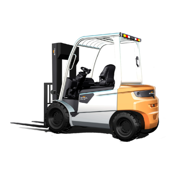
This forklift range includes the following mod- els: Electric forklift trucks in this range: RCE 30,RCE 35, RCE 30 Li-Ion, RCE 35 Li-Ion If you require further information on the differ- ent versions, contact your authorised dealer. -
Page 13: General
Introduction Your industrial truck Operation On single-pedal models, the drive motor is controlled by the forward pedal and reversing switch; on dual-pedal models, the drive motor is controlled by forward and reverse accelera- tor pedals. Forward and reverse speeds can be adjusted between standstill and maximum speed. -
Page 14: Conformity Marking
Introduction Your industrial truck The industrial truck is fitted with state-of-the- art technology. Following these operating in- structions will allow the industrial truck to be handled safely. By complying with the speci- fications in these operating instructions, the functionality and the approved features of the industrial truck will be retained. -
Page 15: Declaration That Reflects The Content Of The Declaration Of Conformity
Your industrial truck Declaration that reflects the content of the declaration of conformity Declaration STILL GmbH Berzeliusstraße 10 22113 Hamburg Germany We declare that the specified machine conforms to the most recent valid version of the directives specified below: ... -
Page 16: Nameplate
Introduction Your industrial truck Nameplate 1 Nameplate 2 Manufacturer 3 Model/Product no./Year of manufac- ture 4 Unladen mass 5 Battery weight (max./min.) 6 Service weight 7 Placeholder for "Data matrix code" 8 Conformity marking: CE mark for the markets of the EU, the EU candidate countries, the EF-... -
Page 17: Using The Truck
Introduction Using the truck Using the truck Commissioning Commissioning is the initial intended use of the truck. The necessary steps for the commissioning vary depending on the model and equipment of the truck. These steps require preparatory work and adjustment work that cannot be per- formed by the operating company. -
Page 18: Intended Use
Introduction Using the truck Intended use The industrial truck may be used only for its provided so that trucks can drive over these intended purpose. obstacles with as few bumps as possible. The industrial truck is intended for moving and Industrial trucks may only be used on road- lifting the loads specified on the capacity rat- ways that do not have curves that are too... -
Page 19: Improper Use
Introduction Using the truck Attachment operating instructions are en- must only be performed by authorised person- closed for industrial trucks that are delivered nel in accordance with the information provi- from the factory with an attachment. Before ded by the manufacturers. After each assem- commissioning an industrial truck with an at- bly process, the function of the attachment tachment, check that loads are handled safe-... -
Page 20: Precautions
Introduction Using the truck Do not use the forks or any other part of the When raising a spreader, ensure that there is truck to push, pull or support items, unless the enough clearance. design permits this. When working near overhead power lines, ob- serve the safety distances set by the compe- tent authorities. -
Page 21: Parking In Temperatures Below -10 °C
Introduction Using the truck – Ambient temperature ranging from-20 to + 40°C for truck with lead-acid batteries. – Ambient temperature ranging from-10 to + 40°C for truck with lithium-Ion batteries. – Use at up to 2000 metres above sea level. Special uses (applies to trucks with spe- cial equipment) –... -
Page 22: Information About Documentation
Introduction Information about documentation Information about documentation Documentation scope Operating instructions fully and must be available to the driver and ● operator at all times. Operating instructions for attachment parts ● (special equipment) If the operating instructions are lost, the oper- Spare parts list ●... -
Page 23: Issue Date And Topicality Of The Operating Instructions
The issue date and the version of these op- erating instructions can be found on the title page. STILL is constantly engaged in the further de- velopment of trucks. These operating instruc- tions are subject to change, and any claims based on the information and/or illustrations contained in them cannot be asserted. -
Page 24: Explanation Of Signal Terms Used
Introduction Information about documentation Explanation of signal terms used DANGER Indicates procedures that must be strictly adhered to in order to prevent the risk of fatalities. WARNING Indicates procedures that must be strictly adhered to in order to prevent the risk of injuries. CAUTION Indicates procedures that must be strictly adhered to in order to prevent material damage and/or destruc-... -
Page 25: Date Of Edition And Latest Update Of This Manual
Introduction Information about documentation Date of edition and latest update of this manual The publication date of these operating in- structions is printed on the cover sheet. The manufacturer makes continuous efforts to improve its industrial trucks, and therefore re- serves the right to implement changes and to accept no claims concerning the information provided in this manual. - Page 26 Introduction Information about documentation Abbrevi- Meaning Explanation ation maximum Force Maximum power German authority for monitoring/issuing regulations for worker protection, environ- Gewerbeaufsichtsamt mental protection, and consumer protec- tion Transfer of data packets in wireless net- GPRS General Packet Radio Service works ID no.
-
Page 27: Definition Of Directions
Introduction Information about documentation Abbrevi- Meaning Explanation ation Verband Deutscher Maschinen- und Anla- German Mechanical Engineering Industry VDMA genbau e. V. Association WLAN Wireless LAN Wireless local area network Definition of directions The directions "forwards" (1), "backwards" (3), "right" (2) and "left" (4) refer to the installation position of the parts as seen from the driver's compartment;... -
Page 28: Environmental Considerations
Introduction Environmental considerations Environmental considerations Packaging During delivery of the truck, certain parts are packaged to provide protection during trans- port. This packaging must be removed com- pletely prior to initial start-up. ENVIRONMENT NOTE The packaging material must be disposed of properly after delivery of the truck. -
Page 29: Safety
Safety... -
Page 30: Safety Guidelines
Safety Safety guidelines Safety guidelines The operating company or the person it has DANGER commissioned must ensure that the driver un- Safety systems (e.g. the seat switch) are in place to derstands all safety information and that all di- ensure safety. rectives and safety regulations are observed. - Page 31 Safety Safety guidelines Working on the truck Safety information for electromagnetic compatibility DANGER WARNING Any additional bores or welding on the overhead guard will compromise its rigidity. In operating areas with magnetic fields that have a It is therefore strictly prohibited to drill holes in the magnetic flux density greater than 5 mT, unintention- overhead guard or to perform welding work on it.
-
Page 32: Special Notes For Using Lithium-Ion Batteries
– Do not connect the battery with the polarity reversed. Permissible lithium-ion batteries – Use only lithium-ion batteries that have been approved by STILL for use with this truck. Declaring the use of lithium-ion batter- We recommend that the operating company informs the local fire brigade of the planned use of trucks fitted with lithium-ion batteries. - Page 33 Safety Special notes for using lithium-ion batteries perform a separate hazard assessment in or- der to assess the risks posed to the company by lithium-ion batteries. – Observe the national regulations for the country in which the truck is being used. Driver qualification In addition to the prerequisites set out in the chapter entitled "Definition of responsible per-...
-
Page 34: Stability
Safety Stability Stability Turning on and driving diagonally across Stability is guaranteed if your industrial truck is ● descents or ascents used according to its intended use. Driving on descents or ascents with the ● The following actions may jeopardise stability: load on the downhill side Driving with a raised load Loads that are too wide... -
Page 35: Definition Of Terms Used For Responsible Persons
Safety Definition of terms used for responsible persons Definition of terms used for responsible persons Specialist A qualified person is defined as a service en- gineer or a person who fulfils the following requirements: A completed vocational qualification that ● demonstrably proves their professional ex- pertise. -
Page 36: Drivers
Safety Definition of terms used for responsible persons Drivers This truck may only be driven by suitable per- sons who are at least 18 years of age, have been trained in driving, have demonstrated their skills in driving and handling loads to the operating company or an authorised represen- tative, and have been specifically instructed to drive the truck. - Page 37 Safety Definition of terms used for responsible persons Prohibition of use by unauthorised per- sons The driver is responsible for the truck during working hours. He must not allow unauthor- ised persons to operate the truck. When leaving the truck, the driver must secure it against unauthorised use, e.g.
-
Page 38: Basic Principles For Safe Operation
Safety Basic principles for safe operation Basic principles for safe operation Insurance cover on company premises The company premises are very often restric- ted public traffic areas. NOTE It is advisable to review the operational lia- bility insurance so that insurance covers the truck with respect to third parties in the event of damage caused in restricted public traffic areas. - Page 39 Safety Basic principles for safe operation We warn against installing and using restraint systems that have not been approved by the manufacturer. – Contact the authorised service centre be- fore converting or retrofitting the truck. Only the authorised service centre is permit- ted to perform welding work on the industrial truck.
-
Page 40: Changes To The Overhead Guard And Roof Loads
We recommend that you obtain approval from the by STILL. manufacturer and, if applicable, from the relevant regulatory authorities before installing such parts. The manufacturer accepts no liability for any damage caused by the use of non-original parts and non-orig- inal accessories. -
Page 41: Medical Devices
Safety Basic principles for safe operation ries) is permitted only with the approval of the manufacturer. Medical devices The operation of medical devices, for example pacemakers or hearing aids, can be impaired. Check with your doctor or manufacturer if the medical devices are sufficiently protected against electromagnetic interference. -
Page 42: Damage, Defects And Misuse Of Safety Systems
Safety Basic principles for safe operation (e.g. always replace right and left wheels at the same time). Changes must only be made following consultation with the manufacturer. Wheels approved by the manufacturer can be found on the spare parts list. If other wheels are to be used, authorisation from the manu- facturer must be obtained beforehand. -
Page 43: Exercise Caution When Handling Gas Springs And Accumulators
Safety Basic principles for safe operation safely on the fork arms may move forwards and fall. If the fork arms are too long, they can catch on loading units behind the load that is to be picked up. These other loading units then fall over when the load is raised. -
Page 44: Residual Risks
Safety Residual risks Residual risks Residual dangers, residual risks Despite working with care and complying with the standards and regulations, the possibility of other dangers arising when using the truck cannot be ruled out. The truck and all other system components comply with current safety requirements. -
Page 45: Special Risks Associated With Using The Truck And Attachments
Safety Residual risks ments, this can lead to an accident. In this case, the manufacturer is exempt from liability. Stability The stability of the truck has been tested to the latest technological standards. If the truck is used in the proper manner and in accord- ance with its intended use, the stability of the truck is guaranteed. - Page 46 Safety Residual risks use the truck correctly and without the risk of accidents. 36 5001 801 1627 EN - 03/2023 - 03...
- Page 47 Safety Residual risks 5001 801 1627 EN - 03/2023 - 03 37...
-
Page 48: Overview Of Hazards And Countermeasures
Safety Residual risks Overview of hazards and countermeasures NOTE This table is intended to help evaluate the hazards in your facility and applies to all drive types. It does not claim to be complete. – Observe the national regulations for the country in which the truck is being used. - Page 49 Safety Residual risks Hazard Course of action Check note Notes √ done - Not applicable Impermissible usage Provide operating in- German Ordinance on (improper usage) structions Industrial Safety and Health (BetrSichV) and German Health and labour protection law (ArbSchG) Written notice of in- German Ordinance on struction to driver Industrial Safety and...
-
Page 50: Danger To Employees
Safety Residual risks Hazard Course of action Check note Notes √ done - Not applicable DGUV rule 113-001 and observe the oper- ating instructions When operating driverless transport systems Roadway quality inad- Clean/clear roadways German Ordinance on equate Industrial Safety and Health (BetrSichV) Loading equipment in- Reposition load on pal-... - Page 51 Safety Residual risks The design and equipment of the truck comply with the standards and directives required for CE conformity. The design and equipment al- so comply with the standards and directives necessary for the UKCA compliance that is required in the United Kingdom. The design and equipment are therefore not part of the required scope of the hazard assessment.
-
Page 52: Safety Tests
Safety Safety tests Safety tests Regular safety inspection of the truck Safety inspection based on time and ex- traordinary incidents The operating company must ensure that the truck is checked by a specialist at least once a year or after particular incidents. As part of this inspection, a complete check of the technical condition of the truck must be performed with regard to accident safe-... - Page 53 Safety Safety tests – For insulation testing, contact the author- ised service centre. The exact procedure for this insulation testing is described in the workshop manual for this truck. NOTE The truck's electrical system and drive batter- ies must be checked separately. Test values for the drive battery Recommended Nominal volt-...
-
Page 54: Safety Regulations For Handling Consumables
Safety Safety regulations for handling consumables Safety regulations for handling consumables Permissible consumables Refer to the maintenance data table for the WARNING permissible substances necessary for opera- Consumables can be dangerous. tion. It is necessary to follow the safety regulations when handling these substances. -
Page 55: Disposal Of Consumables
Safety Noise level WARNING Battery acid contains dissolved sulphuric acid. This is corrosive. – When working with battery acid, use appropriate PSA (rubber gloves, apron, protection goggles). – When working with battery acid, nev- er wear a watch or jewellery. –... -
Page 56: Frequency Characteristics For Vibrations Imparted To The Human Body
Safety Frequency characteristics for vibrations imparted to the human body NOTE The noise level may be higher or lower than this value when operating the forklift truck. Dif- fering tasks and external factors may lead to an increase in noise levels. Frequency characteristics for vibrations imparted to the hu- man body... -
Page 57: Manually Lowering The Fork Arms With Iso
Safety Manually lowering the fork arms with ISO NOTE If the truck has a driver's cab with a door, a window and glass, it is difficult for the driver to open the door from the side when the truck encounters a fault in narrow passages. In the event of such dire danger, the driver can exit the truck via the rear window. -
Page 58: Safety Regulations Relative To Forklift Use
Safety Safety Regulations Relative to Forklift Use – Slowly turn the emergency lowering screw about 1.5 turns anticlockwise using a hexa- gon socket wrench. – Gently push the joystick until the forks are completely lowered. – After it is lowered, turn back the emergen- cy lowering screw clockwise with 2.5 tightening torque. -
Page 59: Safety Regulations When Driving
There is a risk of accident! – Do not use devices during travel or when handling loads. – Set the volume so that warning signals can still be heard. 5001 801 1627 EN - 03/2023 - 03 49... -
Page 60: Safety Regulations In Case Of Accidental Lateral Tipping
Safety Safety regulations in case of accidental lateral tipping WARNING In areas where use of mobile phones is prohibited, use of a mobile phone or radio telephone is not per- mitted. – Switch off the devices. Visibility when driving The driver must look in the drive direction and have a sufficient view of the driving lane. -
Page 61: Overview
Overview... -
Page 62: General View
Overview General view General view Lift mast Counterweight Lift cylinder Towing pin Handhold Rear cover Steering wheel Driver's seat Reversing handle Multilever Steering column adjustment screw Overhead guard Fork carriage Display unit Forks Rear wheel (steering wheel) Parking brake pedal Front wheel (load wheel) Drive axle USB interface... -
Page 63: Controller And Display Unit
Overview Controller and display unit Controller and display unit Steering column adjustment screw Driver's seat Steering wheel Brake pedal Horn button Accelerator pedal Lighting control handle Lifting device lever Switch panel Tilting device lever Emergency off switch Attachment lever (optional) Display unit Attachment lever (optional) USB interface... -
Page 64: Warning Label Diagram
) Label, Read the operating manual ( For Label, capacity rating plate ( For hook-on heater configuration) side shifter ) Label text, Still + RCE30/RCE35 Label, Lifting/Lowering Label,Li-ion technology (*Li-ion truck) Label,Side shifting Label text, Still Label, Lifting/Lowering/Tilting... -
Page 65: Display Unit
Overview Display unit Display unit Back button Remaining battery run time Up button Hour meter Down button Low charge Enter/modify button Additional information Direction Error symbol Speed Operator symbol Left turn Fasten seat belt symbol Maintenance time Battery cover open symbol Date Parking brake symbol Performance mode... -
Page 66: Switch Panel
Overview Switch panel Refer to truck documentation CAN communication symbol Motor temperature too high (yellow)/over- Connection to Wi-Fi equipment symbol heated (red) KCCU (KION China Communication Unit) Battery charging symbol 4G signal Switch panel Standard or higher lighting Warning lights Working spotlight positions 3/4 or working Screen heating push button spotlight positions 1/2 (for higher lighting) -
Page 67: Relays And Fuses Overview
Overview Relays and fuses overview Relays and fuses overview The relay and fuse box of the truck are in- stalled above the counterweight and can be viewed by opening the cover above the coun- terweight. See figure on right: (1): Flashing relay, reversing relay, brake ●... - Page 68 Overview Relays and fuses overview Relay Signs Function 5N20 Flashing light relay Reversing relay Parking relay Motor fan relay Module fan relay 58 5001 801 1627 EN - 03/2023 - 03...
- Page 69 Overview Relays and fuses overview Fuses Signs Specifications Function 80V/10A Key and main contactor signal 32V/10A Module control unit and drive motor speed sensor 32V/10A Display unit, diagnostics 32V/10A Horn, fan, flasher, brake light, reversing light, reversing beeper 32V/10A USB charging port, combination switch Spare (lead-acid battery models), BMS auxiliary battery (lithium- 32V/10A...
- Page 70 Overview Relays and fuses overview 60 5001 801 1627 EN - 03/2023 - 03...
-
Page 71: Operation
Operation... -
Page 72: Service Plan Before First Start
Operation Service plan before first start Service plan before first start Drive mechanism and transmission system Check the drive axle/transmission gear oil level. Check and tighten the wheel nuts. Check the tyre pressure (if fitted with optional pneumatic tyres). Check the functionality of the service brake and parking brake. Check the drive functions (forward and reverse). - Page 73 Operation Pre-shift checks forklift truck in good condition. These checks are supplemental and do not replace periodic maintenance work. NOTE If, when carrying out the daily checks, you discover a defect or you are unsure whether the truck will function properly, do not use the truck and contact the technical service depart- ment.
-
Page 74: Daily Inspection Items
Operation Daily inspection items Daily inspection items Drive mechanism and transmission system Check the tyre and rim (for damage to the profile and outer section). Check the drive axle/transmission gear oil level. Check the tyre pressure (if fitted with optional pneumatic tyres). Test the functionality of the service brake and parking brake. -
Page 75: Periodic Inspection Items
Operation Periodic inspection items Periodic inspection items CAUTION Carrying out periodic inspections of the vehicle is supplemental to periodic servicing work and plays an important role in keeping the vehicle in good working order. Please carry out periodic inspections accord- ing to the content of the "Table of first service checks"... - Page 76 Operation Troubleshooting guide Fault Possible reason Solution 1. The battery plug is not connec- 1. Check the battery plug and connect it if ted. necessary. 2. The emergency off switch is 2. Pull up the emergency off switch. pressed. 3. The key switch is in position 3.
-
Page 77: Mounting/Dismounting
Operation Mounting/dismounting Mounting/dismounting WARNING Always face the vehicle when climbing off the forklift to prevent injury to legs and back. NOTE Do not grip the steering wheel or joysticks when climbing on/off the forklift. After completing the daily checks on the forklift truck, carry out the following procedure to be- gin using it: –... -
Page 78: Seat Belt Status And Performance Checks
Operation Seat belt status and performance checks Seat belt status and performance checks Checking condition and performance DANGER CAUTION For safety reasons, the condition and protective The seat belt must be replaced if it is cracked, worn ability of the seat belt must be checked on a daily or has been damaged in an accident. - Page 79 Operation Seat belt status and performance checks between driver, steering wheel, accelerator pedal and operating levers is found. – Retract the adjustment handle (1). Setting the driver's weight NOTE The individual driver's weight must be set with the driver sitting in the seat. –...
- Page 80 Operation Seat belt status and performance checks Fastening the seat belt DANGER There is a risk to life if the driver loses control of the vehicle. The seat belt must be worn at all times that the truck is driven! The seat belt must only be used by one person at any time.
-
Page 81: Seat Belt Monitoring And Alarm Function
Operation Seat belt status and performance checks – Slowly pull the seat belt (3) out from the retractor (1). – Place the seat belt around the waist, no higher than the abdomen. – Press the seat belt latch plate (2) into the latch (4). -
Page 82: Operating The Horn
Operation Operating the horn arrow in the display unit will flash. If the vehi- cle speed is above 4 km/h at this time, the beeper will also sound. Different monitoring modes can be set using the diagnostic software so that the forklift truck gradually slows down to a standstill (0 km/h) or is restricted to creep speed (2 km/h). -
Page 83: Checking The Steering System For Correct Function
Operation Checking the steering system for correct function Checking the steering system for correct function DANGER If the hydraulics fail, there is a risk of accident as the steering characteristics have changed. – Do not operate the truck if it has a defective steer- ing system. -
Page 84: Emergency Off Switch
Operation Emergency off switch Adjusting the angle – Loosen the clamping screw (1) anti-clock- wise. – Move the steering column into the required position. – Tighten the clamping screw (1) clockwise. Emergency off switch DANGER This switch button is the primary power switch. Do not disconnect this switch when performing an emergency stop. - Page 85 Operation Emergency off switch Pulling up the emergency off switch – Pull up the emergency off switch (1). This will cause the truck's electrical system to start conducting. The truck is ready for use. NOTE The truck is only operational after correctly pulling up the emergency off switch.
-
Page 86: Keypad 安装与使用(*选装
Operation Keypad 安装与使用(*选装) Keypad 安装与使用(*选装) RFID Keypad – The truck is equipped with an RFID Keypad with driver identification system. The instal- lation position is as shown on the right: NOTE The system is standard on vehicles in China only. - Page 87 Operation Keypad 安装与使用(*选装) Unlocking with a password – Turn on the key switch, and a red indicator (R) on the keypad will light up. – Enter the correct driver password and press button. The red indicator (R) will be off and the green indicator (G) will lights up.
- Page 88 Operation Keypad 安装与使用(*选装) – Enter the 3-digit function code 0 0 4 press the button. – Enter an existing 5-digit driver password. – Press to delete the password, or press to cancel the deletion. Press and hold the button for 1 second to exit the administrator mode.
-
Page 89: Switching The Truck On And Off
Operation Switching the truck on and off and both the red indicator and green indica- tor will blink. If an unbound ID card is bound to a bound ● driver number (00–99), the ID card original- ly bound to the driver number will become invalid. - Page 90 Operation Switching the truck on and off – Depress the parking brake pedal (9). The pedal will rebound and the parking brake will disengage. – Observe the display unit (7). NOTE Ensure that the parking brake is fully disen- gaged. The truck cannot be driven until the parking symbol Ⓟ...
- Page 91 Operation Switching the truck on and off – Depress the parking brake pedal (9) to ac- tuate the parking brake. Observe whether the parking symbol Ⓟ remains lit on the display unit (7). – Turn the switch key anticlockwise to the zero position.
-
Page 92: Setting The Display Unit
Operation Setting the display unit Setting the display unit Setting the main interface – Long press the Enter/Modify button the display unit to access the settings page. – The settings page contains the following four setting items: Display settings ●... - Page 93 Operation Setting the display unit – Access the "Date format" settings menu to change the date format. (month.day.year 24-hour, day.month.year 24-hour, month/day/year 12-hour) – Access the "Date" settings menu to change the date. – Access the "Time" settings menu to change ...
- Page 94 Operation Setting the display unit – Access the "system information" to read the system information of the display unit, such as the vehicle model and the software ver- sion of the display unit. NOTE The "Display settings" are settings for use by customers, whereas the other settings are for use by technicians.
-
Page 95: Driving
Operation Driving Driving Driving CAUTION For reasons of stability and minimum braking dis- tance, do not use the forklift truck on a long slope with a gradient of more than 15%. If you need to use the forklift truck on slopes with higher gradients, please first consult your dealer. -
Page 96: Forward Travel
Operation Driving – Sit down on the driver's seat (10) (Only then is the seat switch under the driver's seat activated). – Fasten the seat belt. – Pull up the emergency off switch (6) if nec- essary. – Make sure that the parking brake pedal (9) is actuated. -
Page 97: Reverse Travel
Operation Driving Reverse travel – Set the reversing handle (16) to the reverse position. – Smoothly depress the right-hand accelera- tor pedal (12). The display unit displays the reversing sym- bol. Driving speed accelerates in relation to the increase in pedal travel. NOTE Rapidly depressing the pedal will not change the acceleration, as the maximum acceleration... -
Page 98: Brake System
Operation Brake system Brake system Brake system information WARNING WARNING Risk of accident or casualties if brake system is faul- The braking characteristics of the truck are influ- enced by the viscosity of the oil, among other things. Using a different oil (with a different viscosity) to that Your truck should not be used under any circumstan- prescribed by the manufacturer will affect braking ces if the brake system is faulty. -
Page 99: Electronic Regenerative Braking
Operation Brake system Electronic regenerative braking – Release the accelerator pedal (1) so that the pedal returns to the neutral position. En- ergy is recovered and a braking effect is produced. This truck is equipped with the automatic brake control system. Slowly or quickly releas- ing the accelerator pedals to the neutral posi- tion allows the braking effect to be sensitively controlled, from gentle to hard braking. -
Page 100: Parking Brake
Operation Brake system Parking brake WARNING If there is a fault with the braking system or system parts are worn, contact your authorised authorized dealer. The forklift truck must not be operated if there are problems with the braking system. Applying the parking brake NOTE The truck can be started regardless of wheth-... -
Page 101: Battery Cover - Open - Closed
Operation Battery cover — Open - Closed – The parking symbol Ⓟ on the display unit comes on and remains lit. The truck is braked. Releasing the parking brake – Depress the parking brake pedal and then release. The parking brake will return to its original position. - Page 102 Operation Battery cover — Open - Closed Opening the battery cover NOTE Before doing this, be sure to remove any loose items from the battery cover or from un- der the driver's seat. NOTE If necessary, adjust the steering column and driver's seat when opening the battery cover.
-
Page 103: Checking Battery Charging Status
Operation Checking battery charging status Closing the battery cover CAUTION Do not sit on the battery cover: risk of injury or dam- age. To avoid injury, ensure that personnel are far enough away before closing the battery cover. – Lock the latch by pressing the battery cover down until the latch makes a locking sound. -
Page 104: Charging Precautions (Lead-Acid Battery)
Operation Charging precautions (lead-acid battery) Charging precautions (lead-acid battery) CAUTION NOTE To ensure operational safety and maintain the bat- Check the specific gravity of the electrolytes. tery, please observe the following rules. Always charge and maintain the battery in ac- cordance with instructions from the manufac- turer. - Page 105 Operation Connecting the rechargeable battery to an external charger – Apply the parking brake by depressing the parking brake pedal (1). – Turn the key switch off. – Press the emergency off switch (1). 5001 801 1627 EN - 03/2023 - 03 95...
- Page 106 Operation Connecting the rechargeable battery to an external charger Lead acid batteries – Open the battery cover. – Remove the battery male connector (1) from the forklift power connector(2). – Connect the external charger plug to the battery connector (1). –...
-
Page 107: Check Rechargeable Battery Condition, Electrolyte Level And Specific Gravity (Lead-Acid Battery)
Operation Check rechargeable battery condition, electrolyte level and specific gravity (lead-acid battery). – Connect the external charger plug to the lithium battery connector (1). – Switch on charger. CAUTION When inserting the battery plug, make sure that the plug is fully seated. Check rechargeable battery condition, electrolyte level and specific gravity (lead-acid... - Page 108 Operation Check rechargeable battery condition, electrolyte level and specific gravity (lead-acid battery). CAUTION Deep discharge (more than 20% of the battery rated capacity) will cause the battery life to shorten. CAUTION Always use and maintain the lithium-ion battery in accordance with instructions from the manufacturer. 98 5001 801 1627 EN - 03/2023 - ...
-
Page 109: Lifting Devices And Attachments
Operation Lifting devices and attachments Lifting devices and attachments Operating the lifting device WARNING There is a risk of being trapped between parts due to the movement of the lift mast or attachments. Never stand near or enter the lift mast, or the area between the lift mast and the truck. -
Page 110: Operating Attachments
Operation Lifting devices and attachments Lifting the fork carriage – Push joystick (1)back. Lowering the fork carriage – Push joystick (1)forwards. Tilting the lift mast forward – Push the joystick (2)forwards. Tilting the lift mast backwards – Pull joystick (2)back. DANGER There is an increased risk of falling and tilting when the lift mast is lifted.For this reason, do not step... - Page 111 Operation Lifting devices and attachments NOTE After installing each attachment, a label should be attached to the battery cover spec- ifying the truck's load capacity after the instal- lation.An attachment operating note should al- so be attached to the back of the attachment operating lever.
-
Page 112: Transporting Loads
Operation Transporting loads Transporting loads Load centre distance and load capacity Before lifting goods, the relationship between the weight, load centre of gravity distance and maximum lift height of the goods must be un- derstood. – Load centre distance refers to the distance ... - Page 113 Operation Transporting loads The load capacity of a truck depends on: Type of the lift mast (standard, duplex, tri- ● plex) Lifting height of the installed lift mast ● Tyres of the front axle ● Whether attachments or additional equip- ●...
- Page 114 Operation Transporting loads Capacity rating plate Fork arms dimensions: Maximum width, maximum thickness and maximum length, in mm Note: If larger fork arms are used, an additional capacity rating plate is required. Please contact your authorised dealer. Identification of attachments: Integral sideshift (ISS), suspended sideshift (SS) Lift mast types: Standard lift mast S, duplex lift mast D, triplex lift mast T Truck model name Symbol of load gravity centre...
-
Page 115: Additional Capacity Rating Plate
Operation Transporting loads Load capacity example: Load centre of gravity distance: 600 mm (9). Load lift height: 4145 mm (10). – Locate the intersection of the column of the 600 mm load centre of gravity distance and the row of the 4145 mm lift height. In this example, the maximum permissible load capacity is 2000 kg (11). -
Page 116: Adjusting The Fork Spacing
Operation Transporting loads NOTE The additional capacity rating plate has differ- ent data for different truck series, lift mast series, and attachments. Please refer to the "Capacity rating plate" chapter on how to read the additional capacity rating plate. Adjusting the fork spacing ... -
Page 117: Picking Up A Load
Operation Transporting loads Picking up a load DANGER Do not use the fork arms or pallet to lift a person. Unless equipped with a work frame that matches the design of the truck, the fork arms must not be used to lift a person. -
Page 118: Transporting Pallets
Operation Transporting loads Transporting pallets As a rule, loads (e.g. pallets) must be trans- ported individually. Transporting multiple loads at the same time is only permitted: when instructed by the supervisor and ● when the technical requirements have been ●... -
Page 119: Picking Up A Load
Operation Transporting loads DANGER Loss of stability! Slipping or swinging suspended loads can lead to a loss of stability and cause the truck to tip over. – When transporting suspended loads, observe the following instructions. Instructions for transporting suspended loads: Swinging loads must be prevented by using ●... - Page 120 Operation Transporting loads equipment and incorrectly formed loads must not be stored. – Attach or secure the load to the lifting ac- cessory so that the load cannot move or fall. – Store the load so that the specified aisle width is not reduced by protruding parts.
- Page 121 Operation Transporting loads – Insert the fork as far under the load as pos- sible. Stop the truck as soon as the fork back is resting on the load. The load centre of gravity must be midway between the fork arms.
- Page 122 Operation Transporting loads – Lower the load while maintaining ground clearance. 5060_003-102 – Tilt the lift mast backwards. The load can be transported. 5060_003-101 112 5001 801 1627 EN - 03/2023 - 03...
-
Page 123: Transporting Loads
Operation Transporting loads Transporting loads NOTE Observe the information in the chapter entitled "Safety regulations when driving". DANGER The higher a load is lifted, the less stable it be- comes. The truck can tip over. The load can fall. There is an increased risk of accidents. -
Page 124: Setting Down Loads
Operation Transporting loads – Never drive with a load protruding to the side (e.g. with the sideshift)! Setting down loads DANGER Risk of accident due to changed moment of tilt! Please note that the lift mast can be tilted far enough forward with a raised load to cause the truck to tip over. - Page 125 Operation Transporting loads – Drive up to the stack with the load lowered in accordance with regulations. – Set the lift mast to vertical. – Lift the load to the stacking height. – Approach the rack at a moderate speed. NOTE The tilt speed of the lift mast in this truck is significantly higher than for previous products...
-
Page 126: Driving On Ascending And Descending Gradients
Operation Transporting loads Driving on ascending and de- scending gradients DANGER Danger to life! Driving on ascending and descending gradients car- ries special dangers! – Always follow the instructions below. – On ascending and descending gradients, the load must be carried facing uphill. –... -
Page 127: Tow Coupling
Operation Transporting loads Tow coupling If the truck breaks down, it can be towed using the tow coupling. The tow coupling can only be used for hauling light loads in factory areas. (Pay attention to accident prevention and comply with technical safety regulations) –... -
Page 128: Before Exiting The Truck
Operation Transporting loads – Depress the parking brake pedal (1) until it reaches the locked position. – The parking symbol Ⓟ on the display unit comes on and remains lit. The truck is braked. WARNING Make sure that the truck does not move. NOTE When leaving the truck temporarily, be sure to keep the truck under constant supervision. - Page 129 Operation Transporting loads – Switch off the truck by turning the key to the 0 position. – Remove the key. DANGER Do not switch off the truck by turning the key when the truck is moving. DANGER The handbrake must be applied and the key re- moved before exiting the vehicle.
-
Page 130: Operation In Special Operating Situations
Operation Operation in special operating situations Operation in special operating situations Transport CAUTION Danger of material damage from overloading! If the truck is driven onto a means of transport, the load capacity of the means of transport, the ramps and loading bridges must be greater than the actual total weight of the truck. - Page 131 Operation Operation in special operating situations DANGER Risk of accident from the truck crashing! Steering movements can cause the tail end to veer off the loading bridge towards the edge. This may cause the truck to crash. – Before driving over a loading bridge, ensure that it is installed and secured properly.
- Page 132 Operation Operation in special operating situations Lashing CAUTION Abrasive lashing straps can rub against the surface of the truck and cause damage. – Position slip-resistant pads beneath the lifting points (e.g. rubber mats or foam). – Attach lashing straps (1) to both sides of the ...
-
Page 133: Towing
Operation Operation in special operating situations Towing DANGER The brake system on the towing vehicle may fail. There is a risk of accident! If the brake system of the towing vehicle is not ade- quately sized, the vehicle may not brake safely or the brakes may fail. - Page 134 Operation Operation in special operating situations DANGER People can be crushed between the truck and tow- ing vehicle during manoeuvring. There is danger of death! The towing vehicle may only be manoeuvred and the tow bar may only be attached using a second person as a guide.
-
Page 135: Crane Loading
Operation Operation in special operating situations – Where possible, activate the restraint sys- tems provided. – Release the parking brake. – Select a towing speed that allows the truck and towing vehicle to be effectively braked and controlled at all times. –... - Page 136 Operation Operation in special operating situations Hooking on the lifting straps 6321_003-069 CAUTION Harnesses may damage the truck's paintwork! Harnesses may damage paintwork by chafing and pressing on the surface of the truck. Particularly hard or sharp-edged harnesses, such as wires or chains, can quickly damage the surface.
- Page 137 Operation Operation in special operating situations – In trucks with swing axles, loop the crane belts around counterweight (5), as shown. – Determine the truck's centre of gravity. 6321_003-070 – Set the length of the harnesses so that the ...
- Page 138 Operation Operation in special operating situations – Carefully lift the truck and take care when setting it down at the intended location. 128 5001 801 1627 EN - 03/2023 - 03...
-
Page 139: Storing The Truck
Operation Storing the truck Storing the truck Taking the truck out of operation If the truck will not be used for over two NOTE months, place it in a very well ventilated, frost- free, clean and dry room. Additionally, the If the forklift truck is not in use for over 6 steps below should be followed: months, contact your authorised dealer in or-... - Page 140 Operation Storing the truck During the maintenance process, please make NOTE sure that the forklift truck is stationary on flat ground and that it does not slide. If the forklift truck is used in an extreme envi- ronment (such as excessive heat, excessive Lower the fork carriage and slowly tilt the lift cold or areas with high dust concentrations), mast forward until the truck is stationary.
-
Page 141: Disposal Of Old Trucks
Operation Disposal of old trucks Disposal of old trucks smeared parts, as well as for tyres including The disposal of old trucks is regulated in di- fire protection measures. Suitable storage rective 2000/53/EC from the European Parlia- tanks for fluids such as fuel, AdBlue® (urea ment and Council. - Page 142 Operation Disposal of old trucks 132 5001 801 1627 EN - 03/2023 - 03...
-
Page 143: Maintenance
Maintenance... -
Page 144: Safety Information For Inspection And Maintenance Work
Maintenance Safety information for inspection and maintenance work Safety information for inspection and maintenance work The industrial truck will only remain ready for WARNING operation at all times if the maintenance and Any side doors fitted could fall shut during mainte- inspection tasks are performed at regular in- nance work and trap staff. -
Page 145: Inspection And Maintenance Data
Maintenance Inspection and maintenance data Inspection and maintenance data Consumable/equip- Filling quantity/set- Components ment tings Distilled water As required Battery Acid-free grease As required Electric motors: Cleaning apparatus for Drive motor As required electrical equipment Hydraulic motor Hydraulic system Standard lift mast: 22 L Standard, duplex and Hydraulic oil Duplex mast 22 L... - Page 146 Maintenance Inspection and maintenance data Installation of the drive Hexagon head bolt Tightening torque axle M22x1, 5x55-8.8-ZLS 570 N.m Drive axle connection Socket head screw Tightening torque to lift mast M16x1, 5x80-8.8-A2C 200 N.m Installation of the tilt Hexagon head bolt Tightening torque cylinder M10x25-8.8-ZNS 80 N.m...
-
Page 147: Recommended Fuels And Oils
Maintenance Recommended fuels and oils Recommended fuels and oils ENVIRONMENT NOTE Follow recommendations regarding the use of consumables. Quantity Component Original oil/fluid International standard name Gear oil SAE80W-90 API-GL5 Drive axle 0.25 For brake fluid reservoir DOT4 brake fluid ... -
Page 148: Regular Maintenance
Maintenance Regular maintenance Regular maintenance The following maintenance will help in improv- ing the truck condition and ensure its function- ality. Complete this work as regularly as possible, in accordance with the operating environment. Clean the truck (as required). ● Check and tighten the wheel nuts (after ●... -
Page 149: Table Of First Service Checks
Maintenance Table of first service checks Table of first service checks Maintenance precautions Servicing work requires specialised knowledge and special tools. Please contact your authorised dealer immediately. Preparations Clean the truck (as required). Check that all labels are complete and legible. Read and delete error content. - Page 150 Maintenance Table of first service checks Check handle bellows for damage and replace if necessary. Electrical system Check the working condition of the fan and clean the fan. Check the power module for dirt and clean if necessary. Check whether the main contactor cable is tightly installed and undamaged, and replace it if necessary.
-
Page 151: Service Plan Table
Maintenance Service plan table Service plan table Maintenance precautions Servicing work requires specialised knowledge and special tools. Please contact your authorised dealer immediately. Preparations Clean the truck (as required). Check that all labels are complete and legible. Read and delete error content. Reset the maintenance interval. - Page 152 Maintenance Service plan table Electrical system Check the working condition of the fan and clean the fan. Check the power module for dirt and clean if necessary. Check whether the main contactor cable is tightly installed and undamaged, and replace it if necessary.
- Page 153 Maintenance Service plan table Special equipment Clean and lubricate the sideshift and attachments and check functionality and state of wear (in accordance with the procedures stipulated by the manufacturer). Check the preload of the double hoses for the attachments and adjust if necessary. ...
-
Page 154: Cleaning The Truck
Maintenance Cleaning the truck Cleaning the truck The frequency with which cleaning is required When cleaning with compressed air, remove depends on the application of the truck. If stubborn contamination with a cold cleaning highly abrasive materials, e.g. salt water, fer- solvent. -
Page 155: Drive Mechanism And Transmission System
Maintenance Drive mechanism and transmission system Drive mechanism and transmission system Checking the transmission gear and drive axle for leaks – Remove the rubber mat from the floorplate. – Remove the floorplate. – Check the appearance of the transmission gear and drive axle for evidence of leakage. NOTE If the transmission gear or drive axle is leak- ing, please contact your authorised dealer. -
Page 156: Checking The Installation Of The Transmission Gear
Maintenance Drive mechanism and transmission system Checking the installation of the transmission gear – Check the installation of bolts (1) connect- ing the gearbox and drive axle, bolts (2) connecting the gearbox and chassis, and bolts (3) connecting the gearbox and motor. –... -
Page 157: Checking The Joystick Bellows
Maintenance Drive mechanism and transmission system – Check the brake fluid level (1) in the brake fluid reservoir. If necessary, undo the lid of the brake fluid reservoir (2) and top up with brake fluid. Otherwise, the brakes may fail. Please refer to "Recommended fuels and oils"... -
Page 158: Checking The Wheels
Maintenance Drive mechanism and transmission system Checking the wheels Checking for tyre damage Checking for foreign objects in the tyre Secure the truck to prevent movement. – Apply the parking brake. – Put chocks behind the wheels that do not require lifting. -
Page 159: Check The Tyre Inflation Pressure
Maintenance Drive mechanism and transmission system Antistatic tyres NOTE Under certain circumstances, the truck may become electrostatically charged. The charge level depends on a number of factors, such as the type of tyre, air humidity, floor covering etc. Excessive electrostatic charge is noticed ●... -
Page 160: Tightening The Wheel Nuts
Maintenance Drive mechanism and transmission system – Check the specific inflation pressures of the tyres. – When necessary, inflate and deflate using the inflation valve. NOTE See the " Inspection and maintenance data " chapter for the specified tyre inflation pres- sures. - Page 161 Maintenance Drive mechanism and transmission system CAUTION When using wheels that are not antistatic, pay atten- tion to the antistatic belt. When changing wheels that are not antistatic, the truck must be equipped with an antistatic belt as these wheels are not electro conductive. The antistatic belt must be in permanent contact with the ground.
-
Page 162: Checking The Condition Of The Antistatic Belt
Maintenance Drive mechanism and transmission system – Loosen all nuts on the wheel to be changed. – Lift the truck with a hydraulic jack until the wheel is off the ground. NOTE If front wheels are to be changed, place a chock behind the rear wheels to prevent the truck sliding backwards. -
Page 163: Clean And Lubricate The Steering Axle
Maintenance Drive mechanism and transmission system If non-marking tyres (light-coloured tyres) – Check that the antistatic belt is securely ● are used and the truck is driven in an area seated on the frame floor, check the condi- with a sealed floor, this electrostatic charg- tion and check for wear. - Page 164 Maintenance Drive mechanism and transmission system – Lubricate the connecting rods and steering knuckles by adding grease via the grease nipples. – Lubricate using a grease gun until fresh grease comes out of the bearings. NOTE Regularly applying a small amount of grease is much more beneficial than applying large amounts on an infrequent basis.
-
Page 165: Chassis And Bodywork
Maintenance Chassis and bodywork Chassis and bodywork Checking the connecting bolts of the drive axle and lift mast – Check the installation of the bolts connect- ing the drive axle to the lift mast. – Retighten if necessary. NOTE Check the "Inspection and maintenance da- ta"... -
Page 166: Driver's Cab
Maintenance Driver's cab Driver's cab Checking the pedal group for ease of movement and lubricat- ing as required – Remove the rubber mat from the floorplate. – Remove the floorplate. – Check bolt and joint fastenings for secure positioning. –... -
Page 167: Checking That The Brake System Is Functioning Properly
Maintenance Driver's cab Checking that the brake system is functioning properly Checking whether the parking brake is WARNING working normally There is a risk of accident or death if the braking system is faulty. – Drive the truck on a slope with a 15% gradi- ent while transporting a load corresponding The forklift truck must not be driven if the brake sys- tem is defective. -
Page 168: Electrics/Electronics
Maintenance Electrics/electronics Electrics/electronics Checking the module for dirt ENVIRONMENT NOTE Follow recommendations regarding the use of consumables. The module is installed inside the truck coun- terweight. – Engage the parking brake. – Switch off the truck. – Press the emergency off switch. –... -
Page 169: Checking The Condition Of The Batteries
Maintenance Electrics/electronics Checking the condition of the batteries – Disconnect the battery male connector and WARNING battery female connector. There is a risk of chemical burns from the battery electrolyte (sulphuric acid). – Check whether the battery unit connectors are damaged and whether they are firmly Therefore, when handling battery acid, be sure connected. - Page 170 Maintenance Electrics/electronics – Safety pin (2)facing counterweight. Opening the safety bracket – Twist the bracket(1) upwards. – Slide the bracket(2) in the elongated holes and lift it away. The bracket is secured with a loss prevention cable. 160 5001 801 1627 EN - 03/2023 - ...
- Page 171 Maintenance Electrics/electronics Removing the safety pin – Twist the safety pin that the bracket faces upwards. – Pull the safety pin out. – After opening the safety bracket, removing the safety pin, and you can lift the battery out of the truck.
-
Page 172: Replacing The Battery Using A Suspension Arrangement
Maintenance Electrics/electronics Replacing the battery using a suspension arrangement Replacing the battery using a suspen- sion arrangement (hoist) CAUTION Risk of accident. Only use a suspension arrangement with sufficient load capacity that has been approved by the manu- facturer. Use a hoist and lifting hook with sufficient lift capaci- ty (refer to the technical datasheet for the battery weight). - Page 173 Maintenance Electrics/electronics – Insert the four hooks on the suspension ar- rangement into the special lifting holes (3). WARNING Risk of tipping if the entire suspension arrangement is not lifted. – Carefully lift the battery cover. NOTE The battery can be withdrawn when it is lifted above the sides of the battery compartment.
-
Page 174: Battery Installation
Maintenance Electrics/electronics – Open the battery cover until the mechanical locking devices click into the limit position. – Lift the entire battery suspension arrange- ment using the fork arms (3) of the truck. – Use pull cords (2) to secure the suspension arrangement on the fork arms. -
Page 175: Inspecting And Maintaining The Lithium-Ion Battery
Maintenance Electrics/electronics – Install the battery lock pin(1) and safety bracket(2). NOTE The battery lock pin and safety bracket is used to secure the battery. Remove the battery lock pin and safety bracket before replacing the battery. – Connect the cable connector to the battery connector. -
Page 176: Hydraulics
Maintenance Hydraulics Hydraulics Checking the hydraulic system for leaks – Remove the rubber mat from the floorplate. – Remove the floorplate. NOTE Remove the accelerator connection plug from the floorplate. – Check the hydraulic pump of the working and steering hydraulics, valves, hoses and lines for leaks. - Page 177 Maintenance Hydraulics – Open the battery cover. The hydraulic oil tank is located on the rear right-hand side of the forklift truck. – Unscrew the breather filter (1) and dipstick (2) together. – Use a clean cloth to wipe the dipstick. –...
-
Page 178: Checking The Breather Filter Is Working Normally
Maintenance Hydraulics – Depending on the different types of mast, the oil level should reach the corresponding mark on the dipstick. S/D - Standard mast/Duplex mast ● T - Triplex mast ● – When required, fill the hydraulic oil up to the upper notch. -
Page 179: Checking Installation Of The Tilt Cylinder
Maintenance Hydraulics – Open the breather filter (1) on the hydraulic oil tank. Ensure the sound of air escaping from the oil tank is heard. – Replace the breather filter if you do not hear the sound of ventilation. ENVIRONMENT NOTE Dispose of the old breather filter in an environ- mentally friendly manner. -
Page 180: Lubricating Tilt Cylinder Bearings
Maintenance Hydraulics Lubricating tilt cylinder bearings ENVIRONMENT NOTE Observe information regarding the use of con- sumables. – Check and lubricate the tilt cylinder bear- ings. NOTE Refer to the "Recommended fuels and oils" table for oil types. 170 5001 801 1627 EN - 03/2023 - 03... -
Page 181: Lifting System
Maintenance Lifting system Lifting system Checking the fork arms and the fork arm quick release apparatus – Check the fork arms for serious deforma- tion, abrasion and damage. E.g.:The thickness of the horizontal and ver- tical sections of the fork arms has been re- duced to 90% of the design thickness, or to the minimum thickness stipulated by the fork arm or forklift truck manufacturer.If the fork... -
Page 182: Checking The Working Condition And Installation Of The Lift Mast, Lifting Chains And Lift Cylinder
Maintenance Lifting system Checking the working condition and installation of the lift mast, lifting chains and lift cylinder – Clean the mast channel and lifting chains. – Check the working status of the lifting chains, along with any signs of abrasion, paying particular attention to the area around the chain wheels. -
Page 183: Adjusting The Length Of The Lifting Chains And Lubricating Using Chain Spray
Maintenance Lifting system Adjusting the length of the lift- ing chains and lubricating using chain spray Adjusting the length of the lifting chains* NOTE Use over time will cause the lifting chains to stretch. Therefore, it is necessary to check and adjust the lengths of both the left and right chains. -
Page 184: Lubricating The Lift Mast And Chains With Chain Spray
Maintenance Lifting system Adjusting the length of the lifting chains* NOTE Use over time will cause the lift chains to stretch, therefore it is necessary to check and adjust their lengths. – Fully lower the lift mast. – Undo the lock nut (1). –... - Page 185 Maintenance Lifting system – Place an oil collecting trough under the lift mast – Carry out cleaning with an alkyl derivative such as an industrial diesel fuel cleaning agent (please comply with the manufactur- er's safety instructions). – Additives may not be used if using a steam nozzle.
-
Page 186: Special Equipment
Maintenance Special equipment Special equipment Checking the preload of the dou- ble hoses (if equipped with at- tachments) – The double hoses should be preloaded by stretching them 5-10mm per meter based on their original length. – Move the hoses between the retaining clips so as to adjust the preload to the predeter- mined value. - Page 187 Maintenance Special equipment – Add lubricating grease to the oil filling ports (1), (2) and (3) on the fork carriage until fresh grease overflows from the filling port. NOTE The sideshift forks must be lubricated each time the forklift truck is cleaned. *Optional part 5001 801 1627 EN - 03/2023 - ...
- Page 188 Maintenance Special equipment 178 5001 801 1627 EN - 03/2023 - 03...
-
Page 189: Technical Datasheet
Technical datasheet... -
Page 190: Dimensions Overview
Technical datasheet Dimensions overview Dimensions overview 180 5001 801 1627 EN - 03/2023 - 03... -
Page 191: Datasheet
Technical datasheet Datasheet Datasheet 1.1 Manufacturer KION JN KION JN KION JN KION JN RCE 30 RCE 35 1.2 Manufacturer's type designition RCE 30 RCE 35 Li-Ion Li-Ion Drive: electric (battery type, Electric Electric Electric Electric mains, ...), diesel, petrol, fuel gas Operator type: hand, pedestrian, ... - Page 192 Technical datasheet Datasheet 4.19 Overall length l1(mm) 3667 3738 3667 3738 4.20 Length to face of forks l2(mm) 2667 2738 2667 2738 4.21 Overall width b2(mm 1268 1268 1268 1268 sxexl( 45x122x1 50x150x1 45x122x1 50x150x1 4.22 Fork dimensions ISO 2331 Fork carriage to ISO 2328,class/ 4.23 ...
-
Page 193: Eco-Design Requirements For Electric Motors And Variable Speed Drives
Technical datasheet Eco-design requirements for electric motors and variable speed drives 10.2 Oil flow for attachments l/min Sound pressure level at the driv- 10.7 dB(A) er's seat Eco-design requirements for electric motors and variable speed drives All motors in this industrial truck are exempt from Regulation (EU) 2019/1781 because these motors do not meet the description giv- en in Article 2 "Scope", Item (1) (a) and be-... - Page 194 Technical datasheet Eco-design requirements for electric motors and variable speed drives 184 5001 801 1627 EN - 03/2023 - 03...
- Page 195 Index Checking the installation of the drive axle. 146 Checking the joystick bellows..Additional capacity rating plate..Checking the main contactor..158 Address of manufacturer.
- Page 196 Index Display unit......Insurance cover on company premises. . . 28 Disposal Intended use......Battery.
- Page 197 Index Periodic inspection items....65 Service plan before first start... 62 Permissible lithium-ion batteries..Service plan table.
- Page 200 STILL GmbH 5001 801 1627 EN - 03/2023 - 03...
Need help?
Do you have a question about the RCE 30 and is the answer not in the manual?
Questions and answers