Still RX70-20/600 Original Instructions Manual
Diesel truck
Hide thumbs
Also See for RX70-20/600:
- Original instructions manual (432 pages) ,
- Original instructions manual (404 pages) ,
- Original instructions manual (424 pages)

Related Manuals for Still RX70-20/600


Summary of Contents for Still RX70-20/600
- Page 1 Original instructions Diesel truck RX70-20/600 RX70-25 RX70-25/600 RX70-30 RX70-30/600 RX70-35 7394 7395 7396 7397 7398 7399 57378011527 EN - 12/2023 - 07...
- Page 3 ● ing and storage of industrial trucks Internet address and QR code The information can be accessed at any time by pasting the address https://m.still.de/vdma in a web browser or by scanning the QR code. 57378011527 EN - 12/2023 - 07 I...
- Page 4 You can request to download the spare parts list by copying and pasting the address https:// sparepartlist.still.eu into a web browser or by scanning the QR code shown to the side. On the web page, enter the following pass-...
-
Page 5: Table Of Contents
Table of contents Foreword Your truck ............ 2 Description of the truck . - Page 6 65 Display/control unit "STILL Easy Control" ........
- Page 7 Table of contents Operation Checks and tasks before daily use ........ 78 Visual inspections and function checking .
- Page 8 STILL Classic and sprint mode ........
- Page 9 Table of contents Lifting system operating devices ......... . . 191 Controlling the lifting system using a double mini-lever.
- Page 10 STILL neXXt fleet (variant) ........
- Page 11 Table of contents Driver restraint systems (variants)......... . 331 Ceiling sensor (variant) .
- Page 12 Table of contents Towing ............. . . 388 Emergency driving via the drive direction switch/drive direction selection lever .
- Page 13 Dimensions ............ 452 VDI datasheet for RX70-20/600 and RX70-25 ...... 454 VDI datasheet for RX70-25/600 and RX70-30 .
-
Page 15: Foreword
Foreword... -
Page 16: Your Truck
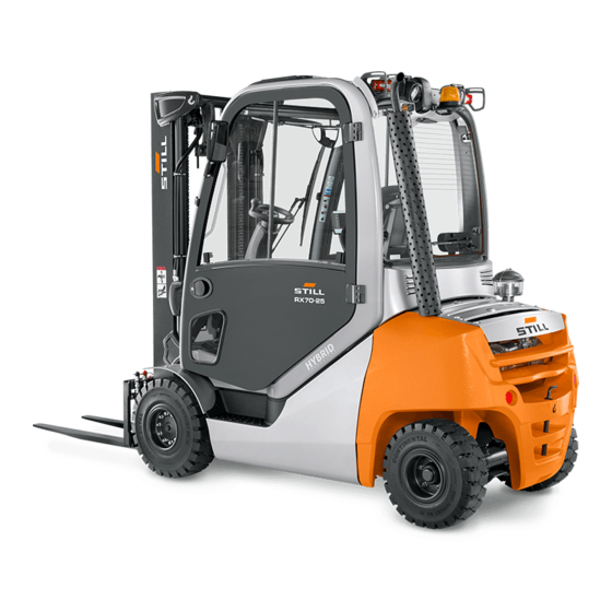
Foreword Your truck Your truck Description of the truck General The trucks in the RX70-20/25/30/35 series with a load capacity of up to 3.5 t are equip- ped with an internal combustion engine/elec- tric drive. This drive combines the advantages of the internal combustion engine with the pre- cise control of an electric drive. - Page 17 Foreword Your truck thanks to speed limitation based on the steer- ing angle. Simple handling of the truck is as- sisted by the manoeuvrable steering axle. Hydraulic system All lift cylinders are hydraulically actuated. The oil volume flow required for the steering and the lift mast is provided by a gear pump connected to the internal combustion engine.
-
Page 18: General
Operational information, such as the fuel lev- el or an indication that the Blue-Q energy- saving mode is enabled, is shown on the STILL Easy Control display-operating unit. For drive mode, the truck features either sin- gle-pedal or dual-pedal operation. The accel- erator pedal is used to accelerate and brake (electric brake) the truck. -
Page 19: Conformity Marking
Foreword Your truck The truck has been fitted with state-of-the-art technology. Following these operating instruc- tions will allow the truck to be handled safely. By complying with the specifications in these operating instructions, the functionality and the approved features of the truck will be retained. Get to know the technology, understand it and use it safely - these operating instructions pro- vide the necessary information and help to... -
Page 20: Declaration That Reflects The Content Of The Declaration Of Conformity
Your truck Declaration that reflects the content of the declaration of conformity Declaration STILL GmbH Berzeliusstraße 10 22113 Hamburg Germany We declare that the specified machine conforms to the most recent valid version of the directives specified below: ... -
Page 21: Accessories
Foreword Your truck Accessories Key for key switch (two pieces) ● Key for cab (variant) ● Hexagon socket wrench for emergency low- ● ering 57378011527 EN - 12/2023 - 07 7... -
Page 22: Labelling Points
Foreword Your truck Labelling points Labelling points on the side 10 bar DANGER DANGER Tyre pressure specification Risk of crushing Fuel plate Manufacturer's logo Note regarding heating system/read the op- HYBRID TECHNOLOGY marking erating instructions 8 57378011527 EN - 12/2023 - 07... - Page 23 Foreword Your truck Labelling points at the front and rear DANGER DANGER Lifting point Do not stand on/under the forks Nameplate Note regarding hot surface/read the operat- StVZO note ing instructions 57378011527 EN - 12/2023 - 07 9...
- Page 24 Foreword Your truck Labelling points in the driver's compartment DANGER 20xx Parking brake emergency release label Decal information: Caution/Read operating Head clearance label instructions/Fasten seat belt/Apply parking specification brake when leaving the truck/Passengers Hydraulic oil label are not allowed/Do not jump off if the truck is FEM testing and inspection sticker tipping over/Lean in the opposite direction to Armrest adjustment (opening the bonnet)
- Page 25 Foreword Your truck Labelling points on the armrest Note regarding ceiling sensor (Variant) Capacity rating plate for attachment 2 (var- Cruise control (variant) iant) Capacity rating plate Capacity rating plate for attachment 1 (var- iant) 57378011527 EN - 12/2023 - 07 11...
-
Page 26: Nameplate
Foreword Your truck Nameplate Nameplate Manufacturer Model/serial number/year of manufacture Tare weight Max. battery weight/min. battery weight Industrial truck / Chariot de manutation / Flurförderzeug (only for electric trucks) Ballast weight (only for electric trucks) Placeholder for "data matrix code" Conformity marking Rated drive power Battery voltage (only for electric trucks) -
Page 27: Stvzo (Road Traffic Licensing Regulations) Information
Foreword Your truck StVZO (Road Traffic Licensing Regulations) information This label includes information on the weight and load distribution of the truck. 7094_003-098_V2 Tare weight (in kg) Permitted total weight (in kg) Permitted front axle weight (in kg) Permitted rear axle weight (in kg) Payload (in kg) 57378011527 EN - 12/2023 - ... -
Page 28: Using The Truck
Foreword Using the truck Using the truck Commissioning Commissioning is the initial intended use of the truck. The necessary steps for the commissioning vary depending on the model and equipment of the truck. These steps require preparatory work and adjustment work that cannot be per- formed by the operating company. -
Page 29: Improper Use
Foreword Using the truck The regulations regarding trailer operation must be observed; see chapter "Trailer opera- tion". Improper use The operating company or driver, and not the manufacturer, is liable for any hazards caused by improper use. NOTE Please note the definition of the following re- sponsible persons: "operating company"... - Page 30 Foreword Using the truck Routes, working areas and aisle widths must conform to the specifications in these oper- ating instructions; see the chapter entitled "Routes". Driving on upward and downward gradients is permitted provided the specified data and specifications are observed; see the chapter entitled "Routes".
-
Page 31: Using Working Platforms
Foreword Using the truck Using working platforms WARNING The use of working platforms is regulated by national law. The use of working platforms is only permitted by virtue of the jurisdiction in the country of use. – Observe national legislation. –... -
Page 32: Information About The Documentation
Foreword Information about the documentation Information about the documentation Scope of the documentation Original operating instructions of the truck ● Original operating instructions of the dis- ● play-operating unit Operating instructions of the installed var- ● iants that are not mentioned in the afore- mentioned original operating instructions "UPA"operating instructions or inserts (de- ●... -
Page 33: Supplementary Documentation
Foreword Information about the documentation The operating instructions are included in the spare parts list and can be reordered as a spare part. The personnel responsible for operating and maintaining the equipment must be familiar with these operating instructions. The operating company must ensure that all users have received, read and understood these operating instructions. -
Page 34: Issue Date And Topicality Of The Operating Instructions
The issue date and the version of these op- erating instructions can be found on the title page. STILL is constantly engaged in the further de- velopment of trucks. These operating instruc- tions are subject to change, and any claims based on the information and/or illustrations contained in them cannot be asserted. -
Page 35: Explanation Of Signal Terms Used
Foreword Information about the documentation Explanation of signal terms used DANGER Indicates procedures that must be strictly adhered to in order to prevent the risk of fatalities. WARNING Indicates procedures that must be strictly adhered to in order to prevent the risk of injuries. CAUTION Indicates procedures that must be strictly adhered to in order to prevent material damage and/or destruc-... -
Page 36: Schematic Views
Foreword Information about the documentation Schematic views View of functions and operating proce- dures At many points in this documentation, the (mostly sequential) operation of certain func- tions or operating procedures is explained. Schematic diagrams of a counterbalance truck are used to illustrate these procedures. - Page 37 Foreword Information about the documentation Abbrevi- Meaning Explanation ation German insurance company for the com- Berufsgenossenschaft pany and employees German principles and test specifications Berufsgenossenschaftlicher Grundsatz for occupational health and safety German rules and recommendations for Berufsgenossenschaftliche Regel occupational health and safety DGUV Berufsgenossenschaftliche Vorschrift German accident prevention regulations...
- Page 38 Foreword Information about the documentation Abbrevi- Meaning Explanation ation Maximum permissible air concentrations Maximum workplace concentration of a substance at the workplace Max. Maximum Highest value of an amount Min. Minimum Lowest value of an amount Personal Identification Number Personal identification number Personal protective equipment ...
-
Page 39: Environmental Considerations
Foreword Environmental considerations Environmental considerations Packaging During delivery of the truck, certain parts are packaged to provide protection during trans- port. This packaging must be removed com- pletely prior to initial start-up. ENVIRONMENT NOTE The packaging material must be disposed of properly after delivery of the truck. - Page 40 Foreword Environmental considerations 26 57378011527 EN - 12/2023 - 07...
-
Page 41: Safety
Safety... -
Page 42: Definition Of Responsible Persons
Safety Definition of responsible persons Definition of responsible persons Operating company The operating company is the natural or legal person or group who operates the truck or on whose authority the truck is used. The operating company must ensure that the truck is only used for its proper purpose and in compliance with the safety regulations set out in these operating instructions. -
Page 43: Drivers
Safety Definition of responsible persons Drivers This truck may only be driven by suitable per- sons who are at least 18 years of age, have been trained in driving, have demonstrated their skills in driving and handling loads to the operating company or an authorised represen- tative, and have been specifically instructed to drive the truck. - Page 44 Safety Definition of responsible persons Prohibition of use by unauthorised per- sons The driver is responsible for the truck during working hours. He must not allow unauthor- ised persons to operate the truck. When leaving the truck, the driver must secure it against unauthorised use, e.g.
-
Page 45: Basic Principles For Safe Operation
Safety Basic principles for safe operation Basic principles for safe operation Insurance cover on company premises In many cases, company premises are restric- ted public traffic areas. NOTE The business liability insurance should be re- viewed to ensure that, in the event of any damage caused in restricted public traffic areas, there is insurance cover for the truck in respect of third parties. -
Page 46: Changes To The Overhead Guard And Roof Loads
Safety Basic principles for safe operation – Contact the authorised service centre be- fore converting or retrofitting the truck. The operating company is only permitted to make modifications to the truck independently if the manufacturer goes into liquidation and the company is not taken over by another le- gal person. -
Page 47: Warning About Any Manipulation Of The Internal Combustion Engine
STILL. CAUTION Installation and/or use of such products may there- fore have a negative impact on the design features of the truck and thus impair active and/or passive driving safety. -
Page 48: Damage, Defects And Misuse Of Safety Systems
Safety Basic principles for safe operation Damage, defects and misuse of safety systems Damage or other defects on the truck or at- tachment must be reported to the supervisor or responsible fleet manager immediately so that they can have the defect rectified. Trucks and attachments that are not functional or safe to drive may not be used until they have been properly repaired. -
Page 49: Medical Equipment
Safety Basic principles for safe operation The following rules must be observed to en- sure stability: Only use tyres with equal and permitted lev- ● els of wear on the same axle Only use wheels and tyres of the same type ●... -
Page 50: Exercise Caution When Handling Gas Springs And Accumulators
Safety Basic principles for safe operation Exercise caution when handling gas springs and accumulators WARNING Gas springs are under high pressure. Improper re- moval results in an elevated risk of injury. For ease of operation, various functions on the truck can be supported by gas springs. - Page 51 Safety Basic principles for safe operation – For help with selecting the correct fork arms, contact the authorised service centre. 57378011527 EN - 12/2023 - 07 37...
-
Page 52: Residual Risk
Safety Residual risk Residual risk Residual dangers, residual risks Despite working with care and complying with the standards and regulations, the possibility of other dangers arising when using the truck cannot be ruled out. The truck and all other system components comply with current safety requirements. -
Page 53: Special Risks Associated With Using The Truck And Attachments
Safety Residual risk ments, this can lead to an accident. In this case, the manufacturer is exempt from liability. Stability The stability of the truck has been tested to the latest technological standards. If the truck is used in the proper manner and in accord- ance with its intended use, the stability of the truck is guaranteed. - Page 54 Safety Residual risk use the truck correctly and without the risk of accidents. 40 57378011527 EN - 12/2023 - 07...
- Page 55 Safety Residual risk 57378011527 EN - 12/2023 - 07 41...
-
Page 56: Overview Of Hazards And Countermeasures
Safety Residual risk Overview of hazards and countermeasures NOTE This table is intended to help evaluate the hazards in your facility and applies to all drive types. It does not claim to be complete. – Observe the national regulations for the country in which the truck is being used. - Page 57 Safety Residual risk Hazard Course of action Check note Notes √ done - Not applicable Impermissible usage Provide operating in- German Ordinance on (improper usage) structions Industrial Safety and Health (BetrSichV) and German Health and labour protection law (ArbSchG) Written notice of in- German Ordinance on struction to driver Industrial Safety and...
-
Page 58: Danger To Employees
Safety Residual risk Hazard Course of action Check note Notes √ done - Not applicable DGUV rule 113-001 and observe the oper- ating instructions When operating driverless transport systems Roadway quality inad- Clean/clear roadways German Ordinance on equate Industrial Safety and Health (BetrSichV) Loading equipment in- Reposition load on pal-... - Page 59 Safety Residual risk The design and equipment of the truck comply with the standards and directives required for CE conformity. The design and equipment al- so comply with the standards and directives necessary for the UKCA compliance that is required in the United Kingdom. The design and equipment are therefore not part of the required scope of the hazard assessment.
-
Page 60: Safety Tests
Safety Safety tests Safety tests Regular safety inspection of the truck Safety inspection based on time and ex- traordinary incidents The operating company must ensure that the truck is checked by a specialist at least once a year or after particular incidents. As part of this inspection, a complete check of the technical condition of the truck must be performed with regard to accident safe-... -
Page 61: Trucks With Particle Filters
Safety Safety tests NOTE Observe the national regulations for the coun- try in which the truck is being used. Trucks with particle filters DANGER Risk to health from exhaust gases! Exhaust gases from internal combustion engines are harmful to your health. In particular, the soot particles contained in the diesel exhaust gas can cause can- cer. -
Page 62: Insulation Testing
Safety Safety tests NOTE Please observe the definition of the follow- ing responsible persons: "operating company" and "competent person". Insulation testing The truck insulation must have sufficient insu- lation resistance. For this reason, insulation testing in accordance with DIN EN 1175 and DIN 43539, VDE 0117 and VDE 0510 must be conducted at least once every year. -
Page 63: Safety Regulations For Handling Consumables
Safety Safety regulations for handling consumables Safety regulations for handling consumables Permissible consumables WARNING Consumables can be dangerous! – Observe general information and safety informa- tion regarding the use of consumables. – Refer to the chapter entitled "Safety regula- tions for handling consumables". –... -
Page 64: Hydraulic Fluid
Safety Safety regulations for handling consumables WARNING Prolonged intensive contact with the skin can result in dryness and irritate the skin! – Avoid contact and consumption. – Wear protective gloves. – After any contact, wash the skin with soap and water, and then apply a skin care product. -
Page 65: Battery Acid
Safety Safety regulations for handling consumables WARNING These fluids are pressurised during op- eration of the truck and are hazardous to your health. – Do not allow the fluids to come into contact with the skin. – Avoid inhaling spray. –... -
Page 66: Diesel Fuel
Safety Safety regulations for handling consumables WARNING Battery acid contains dissolved sulphuric acid. This is corrosive. – When working with battery acid, use appropriate PSA (rubber gloves, apron, protection goggles). – When working with battery acid, nev- er wear a watch or jewellery. –... - Page 67 Safety Safety regulations for handling consumables WARNING Prolonged intensive contact with the skin can result in loss of skin oils and can irritate the skin! – Avoid contact and swallowing. – Wear protective gloves. – After any contact, wash the skin with soap and water, and then apply a skin care product.
-
Page 68: Coolant And Cooling Fluid
Safety Safety regulations for handling consumables Coolant and cooling fluid WARNING Coolant and cooling fluid can be hazard- ous to your health and the environment! Coolants are chemical corrosion inhib- itors and cooling system protecting agents such as Glysantin. The cooling fluid is an appropriate mixture of water and coolant. - Page 69 Safety Safety regulations for handling consumables – Always observe national regulations con- cerning the disposal of used oil. 57378011527 EN - 12/2023 - 07 55...
-
Page 70: Emissions
Safety Emissions Emissions The values specified apply to a standard truck (compare the specifications in the "Technical data" chapter). Different tyres, lift masts, addi- tional units etc. may produce different values. Noise emissions The values were determined based on meas- uring procedures from the standard EN 12053 "Safety of industrial trucks - Test methods for measuring noise emissions", based on... - Page 71 Safety Emissions Time proportions: Lifting 18% ● Idling 58% ● Driving 24% ● However, the indicated noise levels at the truck cannot be used to determine the noise emissions at workplaces according to the most recent version of Directive 2003/10/EC (daily personal noise pollution).
- Page 72 Safety Emissions the applicable national regulations in non-EU countries. NOTE Please note the definition of the following re- sponsible person: "operating company". Exhaust gases DANGER Risk to health from exhaust gases! Exhaust gases from internal combustion engines are harmful to your health. In particular, the soot particles contained in the diesel exhaust gas can cause can- cer.
- Page 73 Safety Emissions Radiation In accordance with the guide- lines DIN EN 62471:2009-03 (VDE 0837-471:2009-03), the STILL Safety- Light (variant) is assigned to risk group 2 (me- dium risk) due to its photobiological hazard potential. 57378011527 EN - 12/2023 - 07 59...
- Page 74 Safety Emissions 60 57378011527 EN - 12/2023 - 07...
-
Page 75: Overviews
Overviews... -
Page 76: Overview
Overviews Overview Overview 73XX_003-001 Rotating beacon (variant) Drive axle Rear working spotlight (variant) Fork arms Rear lighting (variant) Fork carriage Driver's compartment Hydraulic connection for an attachment Exhaust pipe Lift mast Starter battery Front working spotlight (variant) Towing device Overhead guard Steering axle 62 57378011527 EN - 12/2023 - ... -
Page 77: Driver's Compartment
Steering wheel Driver's seat Mini-console Accelerator pedal Key switch Brake pedal Operating devices of the heating system Steering column adjustment lever Display-operating unit "STILL Easy Control" Air vents Operating devices Parking brake Compartment and storage location for oper- FleetManager (variant) ating instructions NOTE The truck equipment may differ from the equipment shown. -
Page 78: Shelves And Cup Holders
Overviews Shelves and cup holders Shelves and cup holders WARNING Risk of accident as a result of objects that are not secure! Objects that are not safely stowed may fall into the footwell and slide between the pedals (3). As a re- sult, the pedals may get stuck. -
Page 79: Operating Devices And Display Elements
Right-hand favourites bar Brightness sensor Lift height restriction The "STILL Easy Control" is a display-operat- ing unit that serves as an operating device for various truck functions, such as lighting or driving dynamics. It uses various symbols, val- ues and display messages to provide informa- tion about the status of the truck, e.g. -
Page 80: Operating Devices For Hydraulic And Driving Functions
– For information about the other display op- tions, see the original operating instructions entitled "STILL Easy Control display-operat- ing unit". NOTE Do not put a label over the brightness sen- sor (21) or cover it with anything. -
Page 81: Double Mini-Lever
Overviews Operating devices and display elements Double mini-lever Drive direction switch "F1" function key Cross lever "Attachments" "Lift mast" 360° lever Function key for the "5th function" Display field for the hydraulic functions Signal horn button 57378011527 EN - 12/2023 - 07 67... - Page 82 Overviews Operating devices and display elements NOTE In the dual-pedal version (variant), the drive ● direction switch (1) is used exclusively to activate the cruise control function (variant). The drive direction is selected exclusively via the pedals in the dual-pedal version. The authorised service centre can assign ●...
-
Page 83: Triple Mini-Lever
Overviews Operating devices and display elements Triple mini-lever Drive direction switch Signal horn button "Auxiliary hydraulics 1" operating lever "F1" function key "Auxiliary hydraulics 2" operating lever "Lift mast" 360° lever Function key for the "5th function" Display field for the hydraulic functions 57378011527 EN - 12/2023 - ... - Page 84 Overviews Operating devices and display elements NOTE In the dual-pedal version (variant), the drive ● direction switch (1) is used exclusively to activate the cruise control function (variant). The drive direction is selected exclusively via the pedals in the dual-pedal version. The authorised service centre can assign ●...
-
Page 85: Quadruple Mini-Lever
Overviews Operating devices and display elements Quadruple mini-lever Drive direction switch Signal horn button "Tilt" operating lever "F1" function key "Auxiliary hydraulics 1" operating lever "Lift/lower" operating lever "Auxiliary hydraulics 2" operating lever Display field for the hydraulic functions Function key for the "5th function" 57378011527 EN - 12/2023 - ... - Page 86 Overviews Operating devices and display elements NOTE In the dual-pedal version (variant), the drive ● direction switch (1) is used exclusively to activate the cruise control function (variant). The drive direction is selected exclusively via the pedals in the dual-pedal version. The authorised service centre can assign ●...
-
Page 87: Joystick 4Plus
Overviews Operating devices and display elements Joystick 4Plus 6210_003-087 Horizontal rocker button for the "3rd hydraul- LED for the clamp locking mechanism (var- ic function", tilting the lift mast iant) Symbols for the basic hydraulic functions Slider for the "4th hydraulic function", e.g. Pictograms for the 5th hydraulic function and side shift frame forwards/backward for the clamp locking mechanism (variant) -
Page 88: Fingertip
Overviews Operating devices and display elements Fingertip Signal horn button Drive direction switch LED for the "5th function" "Lift/lower" operating lever Function key for the "5th function" "Tilt" operating lever LED for the "Clamp release" "F1" function key Operating lever for "Auxiliary hydraulics 1" LED for "F1"... -
Page 89: Travel Direction Selector And Indicator Module (Variant)
Overviews Operating devices and display elements Travel direction selector and in- dicator module (variant) The travel direction selector and indicator module is located on the steering column be- low the steering wheel. NOTE If the drive direction switch on the operating device is defective and the truck stops in a danger area, the drive direction selection lever on the travel direction selector and indicator... - Page 90 Overviews Operating devices and display elements 76 57378011527 EN - 12/2023 - 07...
-
Page 91: Operation
Operation... -
Page 92: Checks And Tasks Before Daily Use
Operation Checks and tasks before daily use Checks and tasks before daily use Visual inspections and function checking WARNING Risk of injury from falling off the truck! When climbing onto the truck, there is a risk of getting stuck or slipping and falling. - Page 93 Operation Checks and tasks before daily use Component Course of action Ensure that the attachments are mounted correctly in accordance with the operating instructions from the manufacturer. Attachments (variant) Perform a visual inspection to ensure that the at- tachments are intact and are leak-tight. Perform checks to ensure that the attachments are working correctly.
- Page 94 Operation Checks and tasks before daily use Component Course of action To activate all available hydraulic functions once, actuate all hydraulic operating devices once. As a general rule: If hydraulic valves have not been operated for a long time, their function may be impaired. This ap- Working hydraulics plies regardless of the type and design of the hy- draulic valves.
-
Page 95: Climbing In And Out Of The Truck
Operation Checks and tasks before daily use Climbing in and out of the truck WARNING Risk of injury when climbing in and out of the truck due to slipping, hitting yourself on parts of the truck or becoming stuck! If the footwell cover is very dirty or smeared with oil, there is a risk of slipping. - Page 96 Operation Checks and tasks before daily use To assist with climbing in and out of the truck, the footwell must be used as a step (5) and the handle (1) must be used for support. The post of the overhead guard (2) can also be used for support.
-
Page 97: Operating The Signal Horn
Operation Checks and tasks before daily use Operating the signal horn – Push the signal horn button (1). The signal horn sounds. NOTE The signal horn is used to warn people against imminent danger or to announce your intention to overtake. Driver's cab ... -
Page 98: Checking The Condition Of The Wheels And Tyres
Operation Checks and tasks before daily use Checking the condition of the wheels and tyres WARNING Risk of accident! With uneven wear or incorrect air pressure, the stability of the truck decreases and the braking distance increases. – Change worn or damaged tyres without delay. WARNING Risk of tipping! Tyre quality affects the stability of the truck. -
Page 99: Checking The Brake System For Correct Function
Operation Checks and tasks before daily use Checking the brake system for correct function DANGER Risk of accident due to failure of the brake system! If the brake system fails, the truck will be insufficient- ly braked or will not be braked at all. –... - Page 100 Operation Checks and tasks before daily use Checking the parking brake on a gradi- ent or a ramp DANGER Risk to life if the truck rolls away! The truck could run people over if the parking brake is not applied. –...
- Page 101 Operation Checks and tasks before daily use CAUTION There is no power steering when the key switch is switched off! The truck is equipped with hydraulic power steer- ing. Switching off the key switch switches off the hydraulics. Steering forces are increased by the re- maining emergency steering function.
-
Page 102: Checking The Steering System For Correct Function
Operation Checks and tasks before daily use Checking the steering system for correct function DANGER If the hydraulics fail, there is a risk of accident as the steering characteristics have changed. – Do not operate the truck if it has a defective steer- ing system. -
Page 103: Checking The Automatic Tow Coupling (Variant)
Operation Checks and tasks before daily use – If the lift mast does not stop in the vertical position, do not use the assistance system. – In this case, contact your authorised service centre. Checking the automatic tow cou- pling (variant) WARNING Risk of trapping or crushing. - Page 104 Operation Checks and tasks before daily use NOTE Always grease the tow coupling after cleaning it. Use lubricating grease as specified in the chapter entitled "Maintenance data table". It is better to apply a little grease to the tow cou- pling frequently than to apply a lot of grease infrequently.
-
Page 105: Driver's Seats
Operation Driver's seats Driver's seats Adjusting the MSG 65 and MSG 75 driver's seat WARNING Risk of accident from sudden adjustment of the seat or of the seat backrest! The inadvertent adjustment of the seat or of the seat backrest can lead to uncontrolled movements by the driver. - Page 106 Operation Driver's seats Moving the driver's seat – Raise the lever (1) and hold it in position. – Push the driver's seat into the required po- sition. – Release the lever. – Ensure that the driver's seat is securely en- gaged.
- Page 107 Operation Driver's seats Adjusting the MSG 65/MSG 75 seat suspension NOTE The MSG 65/MSG 75 driver's seat is de- signed for people weighing between 45 kg and 170 kg. The driver's seat can be adjusted to suit the weight of the individual driver. To ob- tain optimal settings for the seat suspension, the driver must perform the adjustment whilst sitting on the seat.
- Page 108 Operation Driver's seats Adjusting the longitudinal horizontal suspension (variant) If the driver's seat is equipped with the "longi- tudinal horizontal suspension" variant, impacts in the drive direction are damped by additional seat suspension. The locking lever (5) on the left-hand side of the driver's seat activates and locks the longitudinal horizontal suspension.
- Page 109 Operation Driver's seats Adjusting the backrest extension (var- iant) – Adjust the backrest extension (7) by pulling it out and pushing it into the desired posi- tion. To remove the backrest extension, move it past the end stop by firmly pushing it upwards. 6321_003-040_V3 Switching the seat heater (variant) on ...
- Page 110 Operation Driver's seats Swivelling the driver's seat to the right for reverse travel (variant) WARNING Risk of accident due to the seat swivelling. If the driver's seat swivels while the truck is in mo- tion, the seat position is unstable. –...
-
Page 111: Adjusting The Armrest
Operation Driver's seats Adjusting the armrest DANGER There is a risk of accident if the armrest lowers suddenly, causing the driver to move in an uncon- trolled manner. This may result in unintentional actuation of the steering or operating devices and thus cause the truck or load to move in an uncontrolled fashion. - Page 112 Operation Driver's seats Longitudinal seat adjustment As with a standard driver's seat, the lever (1) on the front right-hand side of the driver's seat can be used to adjust the longitudinal position of the driver's seat. – To unlock the driver's seat, pull up the lev- er (1) and hold it place.
-
Page 113: Seat Belt
DANGER Risk of injury if the truck tips over! Even if an approved restraint system is in use, there is still a residual risk that the driver could be injured if the truck tips over. This risk of injury can be reduced through the combined use of the re- straint system and the seat belt. - Page 114 Operation Driver's seats NOTE The buckle has a buckle switch. When the belt was not fastened, the following occurred: The message Close seat belt ● appears on the display-operating unit. The truck will not drive at speeds faster ● than 4 km/h.
- Page 115 Operation Driver's seats Special feature for trucks with HSR re- straint systems (variant) If the bracket is not closed, the message appears Close restraint system in the display. Fastening on a steep slope The automatic blocking mechanism prevents the belt from being extended whenever the truck is on a steep gradient.
- Page 116 Operation Driver's seats Malfunction due to cold – If the buckle or belt retractor are frozen, thaw the buckle or the belt retractor and dry the parts. This prevents the parts from refreezing. CAUTION The seat belt may be damaged by heat! Do not subject the buckle or belt retractor to exces- sive heat when thawing.
-
Page 117: Pre-Shift Check
Operation Pre-Shift Check Pre-Shift Check Description of the Pre-Shift Check (variant) The Pre-Shift Check is a guided dialogue in the display-operating unit. It also helps the driver conduct the necessary "visual inspec- tions and function checking" before everyday use. After the truck has been switched on, the driver must answer questions about the condi- tion of the forklift truck with While the driver is doing this, the truck func-... -
Page 118: Process
The main display contains the message To complete Pre-Shift Check, press This means that the Pre-Shift Check is still active and the truck functions are restricted. – To acknowledge the message, press the 6219_003-265_en softkey. – Switch on and check the function to be tes- ted, e.g. -
Page 119: All Questions
Operation Pre-Shift Check speed. When the parking brake is applied again, the view returns to Pre-Shift Check. At the end of the check, truck functions are restricted if they have been adjusted as a re- action to a negative test result. The message Pre-Shift Check truck restric- shows that truck functions tions active... -
Page 120: Defining The Question Sequence
Operation Pre-Shift Check Is the capacity rating plate present, undamaged, and legible? Is the driver restraint system damaged? Does the horn work? Does the truck lighting work? Do the warning lights work? Is the antistatic belt present and does it have sufficient con- tact with the floor? Is the corona electrode present and clean? Does the parking brake work properly? - Page 121 Operation Pre-Shift Check – Press the softkey. Service – Press the scroll keys until the Pre- menu appears. Shift Check – Press the softkey. Pre-Shift Check Message list Maintenance interval Version list Pre-Shift Check Calibration Fleet manager 6219_003-268_en 57378011527 EN - 12/2023 - ...
-
Page 122: Displaying The History
Operation Pre-Shift Check menu appears. Pre-Shift Check – Press the softkey. Question sequence History Reset restriction Shift start Question sequence Fleet manager 6219_003-269_en Pressing the softkey allows fixed or random question sequences to be selected. The orange activation bar displays the current selection. - Page 123 Operation Pre-Shift Check – Press the softkey. Service – Press the scroll keys until the Pre- menu appears. Shift Check – Press the softkey. Pre-Shift Check Message list Maintenance interval Version list Pre-Shift Check Calibration Fleet manager 6219_003-268_en 57378011527 EN - 12/2023 - ...
-
Page 124: Defining The Shift Start
Operation Pre-Shift Check menu appears. Pre-Shift Check – Press the softkey. History History Reset restriction Shift start Question sequence Fleet manager 6219_003-269_en The Pre-Shift Check display opens. results This display shows all checks and questions that have been answered with the date and Pre-Shift Check results time. - Page 125 Operation Pre-Shift Check NOTE If the truck is equipped with the "FleetManag- er" variant, the shifts are defined on the Fleet- Manager interface. See the relevant operating instructions. – Activate the "Access authorisation for the fleet manager". – Press the ...
- Page 126 Operation Pre-Shift Check menu appears. Pre-Shift Check – Press the softkey. Shift start History Reset restriction Shift start Question sequence Fleet manager 6219_003-269_en In this menu, you can call up the shift to be defined and its start time. The orange activation bar indicates which shifts are activated.
- Page 127 Operation Pre-Shift Check In this menu you can define the shift start. – Enter the time using softkeys 0 to 9 – To , press the button. save Shift start 1 The shift start is now defined. The Pre-Shift Check is always requested from this shift start time.
-
Page 128: Resetting The Truck Restrictions
Operation Pre-Shift Check – Press the scroll button to deactivate the shift. – To confirm, press the button. Shift start 1 The time is shown in grey. The shift is deactivated. The display reverts to the previous menu. There is no activation bar next to this shift. - Page 129 Operation Pre-Shift Check – Press the scroll keys until the Pre- menu appears. Shift Check – Press the softkey. Pre-Shift Check Message list Maintenance interval Version list Pre-Shift Check Calibration Fleet manager 6219_003-268_en menu appears. Pre-Shift Check –...
- Page 130 Operation Pre-Shift Check A question pops up asking if you want to reset the truck restrictions. – To confirm, press the softkey. The full scope of the truck functions is now available. The display reverts to the previous Reset the truck restrictions? The entry remains in the history menu.
-
Page 131: Driver Profiles
Operation Driver profiles Driver profiles Driver profiles (variant) This variant allows up to ten individual driver profiles to be created. The driver is greeted with the selected name after logging in. Once softkey is pressed, the main display appears. Hello, 0,0°... - Page 132 Operation Driver profiles ped with these variants, drivers must select their profiles manually. NOTE Access to the settings menu is only availa- ble if the truck is at a standstill and the park- ing brake is applied. If the parking brake is released prematurely, the settings menu will close.
-
Page 133: Creating Driver Profiles
Operation Driver profiles The orange activation bar displays the current selection. – Press the softkey for the required driver profile. Guido The driver profile is active. The driver is gree- ted with the selected name the next time that Horst the truck is switched on. - Page 134 Operation Driver profiles – Press the soft- Driver profiles key Driver profiles Truck information Display settings Configure favourites Truck settings 6219_003-293_en This menu provides storage space for saving ten driver profiles. – Press the softkey for the required storage location.
-
Page 135: Renaming Driver Profiles
Operation Driver profiles menu is displayed. Driver name – Use the softkeys to enter the desired name. – To confirm, press the button. Driver name The driver profile is active. The driver is gree- ted with the selected name after the next log- Any changes that drivers make to the settings Enter driver name while they are logged in are saved. - Page 136 Operation Driver profiles – Press the Rename driver profiles softkey. Driving programme Rename driver profiles 6219_003-298_en menu is displayed. Driver name – Use the softkeys to enter the desired name. – To confirm, press the button. Driver name Renaming by the fleet manager –...
- Page 137 Operation Driver profiles – Press the Manage driver pro- softkey. files Lift height preselection Auxiliary hydraulics Change PIN codes Manage driver profiles On-board charger Fleet manager 6219_003-296_en – Press the Rename driver pro- softkey. files Rename driver profiles Delete driver profiles Fleet manager 6219_003-297_en...
-
Page 138: Deleting Driver Profiles
Operation Driver profiles menu is displayed. Driver name – Use the softkeys to enter the desired name. – To confirm, press the button. Driver name Enter driver name Horst = Clear = abc -> ABC = Save = Cancel 6219_003-295_en Deleting driver profiles The fleet manager has access authorisation to... - Page 139 Operation Driver profiles – Press the Delete driver profiles softkey. Rename driver profiles Delete driver profiles Fleet manager 6219_003-297_en – Press the softkey for the driver profile to be deleted. The driver profile is deleted. Guido Horst Lisa Driver 4 Available storage position 5 6219_003-294_en...
-
Page 140: Switching On And Starting
Operation Switching on and starting Switching on and starting Engine preheating (variant) Function At ambient temperatures below the freezing point, a preheated engine is easier to start. The starter battery is protected. The engine consumes less fuel. 230 V In trucks with the engine preheating function, a heating element (1) that is connected to a built-in plug (3) in the engine compartment is... -
Page 141: Switching On The Key Switch And Starting The Engine
Operation Switching on and starting – Plug the connecting cable (2) into the built- in socket (3). – Plug the connecting plug (4) into an earthed 230V socket. – Preheat the engine for at least 2 hours. The preheating time may be longer than this depending on the ambient temperature. - Page 142 Operation Switching on and starting WARNING Before switching on the key switch, all visual inspec- tions and function checking must be carried out with- out any defects being identified. – Perform the visual inspections and function check- ing. – Do not operate the truck if defects have been detected;...
-
Page 143: Access Authorisation With Pin Code (Variant)
– Stop the engine immediately. 7071_003-101 – Check the engine oil level and top up if necessary – If the message still appears, contact the author- ised service centre. – Please note the information in the chapter entitled "Malfunctions". - Page 144 Operation Switching on and starting NOTE We recommend that the fleet manager changes this PIN code using their access au- thorisation. See also the section entitled "Ac- cess authorisation for the fleet manager (var- iant)". When the key switch is switched on, the ...
-
Page 145: Access Authorisation For The Fleet Manager (Variant)
Operation Switching on and starting – Press the softkey. Service – Press the scroll keys until the menu appears. Change PIN codes – Press the softkey. Change PIN codes Calibration – Follow the instructions on the display. Relieve hydraulics Shock sensor Change password (access auth.) - Page 146 Operation Switching on and starting date, the authorised service centre must set up a fleet manager password. Standard fleet manager password The standard fleet manager password is "1111". For safety reasons, this standard fleet manager password must be changed af- ter the first use.
- Page 147 Operation Switching on and starting The display changes to the Access au- menu. thorisation – Enter the fleet manager password using the softkeys. – To confirm, press the button. Enter password 6219_003-208_V3_en The message Fleet manager access appears.
- Page 148 Operation Switching on and starting – Press the softkey. Service – Press the scroll buttons until Change password (access menu appears. auth.) – Press the Version list Change password (ac- softkey. cess auth.) – Follow the instructions on the display. Calibration Relieve hydraulics Shock sensor...
-
Page 149: Lighting
Symbols for the lighting and their meanings Parking light Headlights Hazard warning system Rotating beacon STILL SafetyLight Warning zone light Front working spotlights Rear working spotlights Roof working spotlights Only the symbols of the lighting devices that are installed in the truck can be selected. -
Page 150: Driving Lights
Operation Lighting Driving lights – To switch on the parking light (1), push the associated Softkey on the display-operating unit. The front side lights and the tail lights light up. – To switch on the driving light (2), press the associated Softkey on the display-operating unit. -
Page 151: Working Spotlights
Operation Lighting Working spotlights Front and rear working spotlights – To switch on the front working spot- lights (3), push the associated Softkey on the display-operating unit. The front working spotlights light up. – To switch off the front working spot- lights (3), push the Softkey again. -
Page 152: Working Spotlight For Reverse Travel (Variant)
Operation Lighting Working spotlight for reverse travel (variant) In this equipment variant, a working spotlight for reverse travel is fitted on the rear of the overhead guard and provides optimum illumi- nation of the roadway during reverse travel. – Press the softkey. - Page 153 Operation Lighting – To switch on the left or right turn indicator, move the lever (1) to the desired direction. 6219_003-098 The turn indicators and the turn indicator dis- play (2) or (3) on the display-operating unit flash. 08:20 – To switch off the turn indicators, push the lever (1) back to the centre position.
-
Page 154: Hazard Warning System
Operation Lighting Hazard warning system Switching the hazard warning system on and off is different for trucks with and without the StVZO (German Road Traffic Licensing Regu- lations) variant. – To switch on the hazard warning system, push the associated Softkey on the display- operating unit. -
Page 155: Stvzo Equipment
This softkey is used to switch off all light- ing devices that are not permitted on roads subject to German traffic regulations (StVO). This relates to the following variants of lighting equipment: STILL SafetyLight and STILL Safety- ● Light 4Plus Warning zone light and warning zone light ●... -
Page 156: Rotating Beacon
WARNING Danger of damage to eyes from look- ing into the STILL SafetyLight® and STILL SafetyLight 4Plus®. Do not look into the STILL SafetyLight® or STILL SafetyLight 4Plus®. STILL SafetyLight® and STILL Safety- Light 4Plus® are visual warning units de- signed to enable early detection of trucks in... - Page 157 (variant), for exam- ple, it can be used as an additional light for the working spotlight for reverse travel. The STILL SafetyLight® or the STILL Safety- Light 4Plus® can also be switched on and off on the display-operating unit.
-
Page 158: Blue-Q Efficiency Mode
Blue-Q has no influence on: Climbing capability ● Pulling force ● Braking characteristics ● NOTE If no other energy mode is selected, STILL- Classic is automatically active. No pictogram is displayed for STILL-Classic. 144 57378011527 EN - 12/2023 - 07... -
Page 159: Switching Blue-Q On And Off
Operation Blue-Q efficiency mode Switching Blue-Q on and off – To switch on Blue-Q efficiency mode, push the softkey The Blue-Q symbol appears on the display/operating unit and Blue-Q efficiency mode is switched on. – To switch off Blue-Q efficiency mode, push the associated softkey again. -
Page 160: Switching Off Additional Consumers
Operation Blue-Q efficiency mode Switching off additional consumers If the Blue-Q efficiency mode is activated, the controller switches off various additional con- sumers after a few seconds in certain condi- tions. The additional consumers available de- pend on the truck equipment. The following ta- ble shows the conditions that cause additional consumers to be switched off. -
Page 161: Still Classic And Sprint Mode
Operation Blue-Q efficiency mode STILL Classic and sprint mode Drive modes influence the driving perform- ance and the lifting performance of the electric drive. Two different drive modes are available: STILL Classic This mode is active after the truck has been switched on. This mode is... - Page 162 Operation Blue-Q efficiency mode If the truck is automatically switched off, sprint mode can then only be switched on again if the following conditions are met: The temperatures of the drive units and the ● energy supply are not too high The truck has been restarted.
-
Page 163: Driving
Operation Driving Driving Safety regulations when driving Driving conduct The driver must follow the public rules of the road when driving in company traffic. The speed must be appropriate to the local conditions. For example, the driver must drive slowly around corners, in tight passageways, when driving through swing-doors, at blind spots, or on uneven surfaces. - Page 164 There is a risk of accident! – Do not use devices during travel or when handling loads. – Set the volume so that warning signals can still be heard. WARNING In areas where use of mobile phones is prohibited, use of a mobile phone or radio telephone is not per- mitted.
-
Page 165: Roadways
The required aisle widths depend on the di- mensions of the load. For pallets, these are: Aisle width [mm] With pallet With pallet Model Type 1000x1200 800x1200 crosswise lengthwise RX70-20/600 7394 3963 4163 RX70-25 7395 3963 4163 RX70-25/600 7396 4047 4247... - Page 166 Operation Driving It is permitted to drive the truck on the follow- ing ascending and descending gradients: Maximum gradient [%] Model Type With load Without load RX70-20/600 7394 RX70-25 7395 RX70-25/600 7396 RX70-30 7397 RX70-30/600 7398 RX70-35 7399 The stated values are used only to compare the performance of trucks in the same catego- ry.
- Page 167 Operation Driving the truck contour and be damaged or torn off. Examples of these components are: A roof panel that can be opened in the driv- ● er's cab Cab doors ● Condition of the roadways Roadways must be firm, level and free from contamination and fallen objects.
-
Page 168: Selecting Drive Programmes 1 To 3
Operation Driving Selecting drive programmes 1 to The truck has three drive programmes with different preset driving and braking character- istics. The basic principle is that the higher the number of the drive programme selected, the greater the driving dynamics. The drive programme is selected using the display-operating unit under the "Drive" ... -
Page 169: Selecting Drive Programme A Or B
Operation Driving Selecting drive programme A or The truck has two driving programmes for personalised handling and braking character- istics. Unlike the fixed drive programmes "1 to 3", the programs "A" and "B" can be configured. The procedure for this is described in the following section. - Page 170 Operation Driving – Press the associated Softkey for drive programme A drive pro- gramme B The process for configuring the drive pro- grammes using "drive programme A" is ex- plained here. The menu Set drive programme A appears. The following parameters can be set: ●...
-
Page 171: Selecting The Drive Direction
Operation Driving Selecting the drive direction The drive direction of the truck must be selec- ted using the drive direction switch/drive direc- tion selection lever before attempting to drive. The method of actuating the drive direction switch/drive direction selection lever depends on the operating devices that are fitted in the truck. -
Page 172: Actuating The Drive Direction Switch With The Mini-Lever Version
Operation Driving Actuating the drive direction switch with the mini-lever ver- sion – For the "forwards" drive direction, push the drive direction switch (1) forwards. – For the "backwards" drive direction, pull the drive direction switch (1) backwards. NOTE If the drive direction switch (1) is defective and the truck stops in a danger area, the drive direction selection lever on the travel direction selector and indicator module (variant) can be... -
Page 173: Actuating The Drive Direction Switch, Mini-Console Version
Operation Driving Actuating the drive direction switch with the Fingertip version – For the "forwards" drive direction, push the drive direction switch (1) forwards. – For the "backwards" drive direction, pull the drive direction switch (1) backwards. NOTE If the drive direction switch (1) is defective and the truck stops in a danger area, the drive direction selection lever on the travel direction selector and indicator module (variant) can be... - Page 174 Operation Driving – Observe the information in the chapter enti- tled "Safety regulations when driving". The driver's seat is equipped with a seat switch. This seat switch checks whether the driver's seat is occupied. If the driver's seat is not occupied or if the seat switch is mal- functioning, the truck cannot be moved and all lifting functions are locked.
- Page 175 If the truck still cannot be operated, park the truck securely and con- tact the authorised service centre.
-
Page 176: Starting Drive Mode, Dual Pedal Version (Variant)
Operation Driving Starting drive mode, dual pedal version (variant) DANGER Risk to life if the truck rolls away or tips over! – Sit on the driver's seat. – Fasten the seat belt. – Activate the available restraint systems. – Observe the information in the chapter enti- tled "Safety regulations when driving". - Page 177 Operation Driving The indicator for the selected drive direction ("forwards" (1) or "backwards" (2)) lights up on the display-operating unit. NOTE Depending on the equipment, one of the equipment variants activates as a warning for reverse travel: Signal tone ● Warning light ●...
-
Page 178: Operating The Service Brake
If the truck still cannot be operated, park the truck securely and con- tact the authorised service centre. -
Page 179: Actuating The Electric Parking Brake
Operation Driving – Brake the truck by releasing the accelerator pedal (1). – If the braking effect is inadequate, brake using the service brake (2) as well. Zero braking (variant) DANGER Risk of accident! Trucks with zero braking (variant) are not braked when the accelerator pedal is released. - Page 180 – Press the push button (1) to release the parking brake. The traction motor keeps the truck at a stand- still. Manually actuating the electric parking brake when the truck is stationary Applying the parking brake manually – Press the push button (1).
- Page 181 Operation Driving Automatic actuation of the electric park- ing brake when the truck is stationary The electric parking brake is applied automati- cally when the truck is stationary in the follow- ing situations: Automatically triggered actuation when the truck is stationary Cause Effect The electric parking brake will make a noise...
- Page 182 Operation Driving Actuation of the electric parking brake when the truck is in motion Manual actuation when the truck is in motion – Press the push button (1). The truck is braked with the drive unit in ac- cordance with the selected drive programme. Once the truck has come to a standstill, the electric parking brake is applied with an audi- ble sound.
-
Page 183: Malfunctions In The Electric Parking Brake
A possible cause of the malfunction is that the parking brake cannot determine whether 6219_003-006_V2 the truck is stationary or still in motion. The 57378011527 EN - 12/2023 - 07 169... - Page 184 Operation Driving following section describes how to actuate the parking brake when it is faulty: Actuating a faulty parking brake when the truck is stationary There are two ways to apply the parking brake: – Press and hold the push button (1) for at least five seconds and then release the push button.
- Page 185 Operation Driving This function alerts the driver with an audible warning signal if: The driver leaves the driver's seat and it ● has not been possible to apply the parking brake The driver leaves the driver's seat without ● lowering the fork carriage (variant) The driver attempts to switch off the truck ●...
- Page 186 Operation Driving – If the parking brake cannot be applied auto- matically or via the push button, perform an emergency actuation of the parking brake. Refer to the section entitled "Emergency operation of the parking brake" in the chap- ter "Procedure in emergencies". –...
- Page 187 Operation Driving – If the parking brake cannot be applied via the emergency actuation process, secure the truck with wedges so that the truck can- not roll away. – Have the parking brake repaired by an au- thorised service centre. 57378011527 EN - 12/2023 - ...
-
Page 188: Steering
Operation Driving Steering DANGER If the hydraulics fail, there is a risk of accident as the steering characteristics have changed. – Do not operate the truck if it has a defective steer- ing system. – Steer the truck by turning the steering wheel (1) accordingly. -
Page 189: Speed Reduction When The Fork Carriage Is Raised (Variant)
Operation Driving Speed reduction when the fork carriage is raised (variant) If the fork carriage is lifted to a height above 500 mm, this assistance system automatically reduces the speed of the truck. NOTE This lift height can be changed up to 500 mm either by the authorised service centre or with the "Access authorisation for the fleet manag- er"... - Page 190 Operation Driving – Press the Speed restriction for softkey. lift Lift cut-out Run-on time Overload detection Fork wear protection Speed reduction when the fork carriage is raised Fleet manager 6219_003-314_en – Press the softkey. Lift height Lift height Speed restriction Fleet manager 6219_003-321_en...
- Page 191 Operation Driving In this menu you can define the desired height. Speed reduction when NOTE the fork carriage is raised » Lift height The assistance system intervenes automati- cally from 500 mm. Thus, the height can only be freely selected up to 500 mm. Enter desired height –...
- Page 192 Operation Driving – Press the Speed restriction for softkey. lift Lift cut-out Run-on time Overload detection Fork wear protection Speed reduction when the fork carriage is raised Fleet manager 6219_003-314_en – Press the softkey. Speed restriction Lift height Speed restriction Fleet manager 6219_003-321_en...
-
Page 193: Engine Automatic Shut-Off Function (Variant)
Operation Driving In this menu you can define the maximum speed. – Enter the speed using softkeys 0 to 9 Speed restriction – To , press the button. save The menu closes. Enter maximum speed (2...20km / h) km / h 6219_003-193_en Engine automatic shut-off func- tion (variant) -
Page 194: Cruise Control (Variant)
Operation Driving 10 seconds before the response time elap- ses, the following message appears: Switch off combustion engine The following driver responses are possible: Switch off Switch off – No response. combustion combustion engine engine The engine switches off after 10 seconds. –... - Page 195 Operation Driving When the cruise control function is activated, the speed can be saved when driving forwards at a speed of at least 6.0 km/h by pressing a button and the truck can continue driving without the accelerator pedal being actuated. The pictogram ...
- Page 196 Operation Driving Activating cruise control function WARNING Risk of accident from failing to adjust speed! Driving at excessive speeds can cause accidents, e.g. the truck could tip over when cornering. – Adjust speed along the entire distance being trav- elled –...
- Page 197 Operation Driving NOTE The easiest way to deactivate the cruise con- trol function is to touch the accelerator pedal. The following actions deactivate the cruise control function: Actuating the foot brake ● Actuating the parking brake ● Actuating the accelerator pedal ●...
-
Page 198: Parking
Operation Parking Parking Parking the truck securely and switching it off DANGER Risk of fatal injury from being run over if the truck rolls away! – The truck must not be parked on a slope. – In emergencies, secure the truck us- ing wedges on the side facing down- hill. -
Page 199: Wheel Chock (Variant)
Operation Parking Wheel chock (variant) The wheel chock (variant) is used to prevent the truck from rolling away on a slope. – Lift handle (2) on the support mounting. – Remove wheel chock (1) from the support mounting. – Push the wheel chock under a front axle wheel on the side facing the downhill slope. -
Page 200: Lifting
Operation Lifting Lifting Lifting system variants The movement of the fork carriage and the lift mast heavily depends on the following equip- ment: The lift mast with which the truck is equip- ● ped, see C hapter "Types of lift mast", ⇒ ... - Page 201 Operation Lifting The "automatic mast vertical positioning" as- sistance system consists of the following indi- vidual functions: Display of the "Automatic mast vertical posi- ● tioning" feature Automatic startup of the "Automatic mast ● vertical position" feature The truck can also be equipped with only the "mast tilt angle display"...
-
Page 202: Types Of Lift Mast
Operation Lifting Types of lift mast One of the following lift masts may be installed in the truck: Telescopic mast During lifting, the lift mast rises over the outer lift cylinders, bringing the fork carriage with it via the chains (fork carriage rises twice as fast as the inner lift mast). -
Page 203: Malfunctions During Lifting Mode
Operation Lifting Triplex lift mast (variant) During lifting, the inner lift cylinder moves up to free lift (3), and then the outer lift cylinders raise the inner lift mast up to the max. height (2). DANGER Risk of accident due to collision of the lift mast or load with low ceilings or entrances. -
Page 204: Hydraulic Blocking Function
Operation Lifting Load chains not under tension DANGER Danger caused by a falling load! – Make sure that the chain(s) does (do) not become slack when lowering the load. Slack chains can, for instance, result from: Resting the fork carriage or the load on the ●... -
Page 205: Lifting System Operating Devices
Operation Lifting – Sit down on the driver's seat. All the relevant functions of the working hy- draulics will be available again. NOTE If it is not possible to release the block on the hydraulics when the load is raised because of a technical fault, the load must be lowered using the "emergency lowering"... -
Page 206: Controlling The Lifting System Using A Double Mini-Lever
Operation Lifting Controlling the lifting system us- ing a double mini-lever DANGER Reaching into or climbing between moving parts of the truck (e.g. lift mast, sideshifts, working equip- ment, load carrying devices etc.) can lead to seri- ous injury or death and is therefore prohibited. –... - Page 207 Operation Lifting Lifting/lowering the fork carriage To lift the fork carriage: – Move the "lift mast" 360° lever (3) in the direction of the arrow (B). To lower the fork carriage: – Move the "lift mast" 360° lever (3) in the direction of the arrow (A). Tilting the lift mast To tilt the lift mast forwards: –...
-
Page 208: Controlling The Lifting System Using A Triple Mini-Lever
Operation Lifting Controlling the lifting system us- ing a triple mini-lever DANGER Reaching into or climbing between moving parts of the truck (e.g. lift mast, sideshifts, working equip- ment, load carrying devices etc.) can lead to seri- ous injury or death and is therefore prohibited. –... - Page 209 Operation Lifting – Move the "lift mast" 360° lever (3) in the direction of the arrow (A). Tilting the lift mast To tilt the lift mast forwards: – Move the "lift mast" 360° lever (4) in the direction of the arrow (C). To tilt the lift mast backwards: –...
-
Page 210: Controlling The Lifting System Using A Quadruple Mini-Lever
Operation Lifting Controlling the lifting system us- ing a quadruple mini-lever DANGER Reaching into or climbing between moving parts of the truck (e.g. lift mast, sideshifts, working equip- ment, load carrying devices etc.) can lead to seri- ous injury or death and is therefore prohibited. –... -
Page 211: Controlling The Lifting System Using The Joystick 4Plus
Operation Lifting – Move the "lifting/lowering" operating lev- er (3) in the direction of the arrow (A). Tilting the lift mast To tilt the lift mast forwards: – Move the "lift mast" operating lever (4) in the direction of the arrow (C). To tilt the lift mast backwards: –... - Page 212 Operation Lifting Lifting/lowering the fork carriage To lift the fork carriage: – Pull the Joystick 4Plus (1) backwards (B). To lower the fork carriage: – Push the Joystick 4Plus (1) forwards (A). 6210_003-089 Tilting the lift mast To tilt the lift mast forwards: – Tilt the horizontal rocker button (2) to the left (C).
- Page 213 Operation Lifting Fork carriage sideshift To move the fork carriage to the left: – Push the Joystick 4Plus (1) to the left (E). To move the fork carriage to the right: – Push the Joystick 4Plus (1) to the right (F). NOTE The symbols on the Joystick 4Plus indicate the direction of movement of the lift mast or fork carriage.
- Page 214 Operation Lifting Controlling the lifting system us- ing the Fingertip DANGER Reaching into or climbing between moving parts of the truck (e.g. lift mast, sideshifts, working equip- ment, load carrying devices etc.) can lead to seri- ous injury or death and is therefore prohibited. –...
-
Page 215: Selecting Load Programs 1 To 3
Operation Lifting Tilting the lift mast To tilt the lift mast forwards: – Move the "tilting" operating lever (1) in the direction of the arrow (C). To tilt the lift mast backwards: – Move the "tilting" operating lever (1) in the direction of the arrow (D). Movements of the lifting system and meanings of the pictograms Lowering... -
Page 216: Fork Wear Protection (Variant)
Operation Lifting – If the load programs are saved as a favour- ite on a softkey, press the softkey until the number of the desired load program is shown on the display. The number of dynamic bar segments shows the load dynamics of the selected load pro- gram. -
Page 217: Changing The Fork Arms
Operation Lifting Mechanical version Fixed stops in the lift cylinder prevent the fork arms from hitting the ground. No symbol ap- pears in the display-operating unit. This version cannot be adjusted. NOTE The mechanical fork wear protection must be continually adjusted as the wear on the front tyres increases. - Page 218 Operation Lifting Removal – Select a pallet corresponding to the fork arm size. – Set down the pallet next to the fork carriage on the side chosen for removal. – Lift the fork carriage until the fork arms are approx. 3 cm above the pallet.
-
Page 219: Fork Extension (Variant)
Operation Lifting Fork extension (variant) DANGER There is a risk of fatal injury from being run over if the truck rolls away. – Do not park the truck on a slope. – Apply the parking brake. – Change the fork extension in a cordoned-off, safe location on a level surface. - Page 220 Operation Lifting Attaching DANGER Risk of fatal injury from falling load! At least 60% of the length of the fork extension must lie on the fork arm. No more than 40% of the length of the fork extension may overhang the end of the fork arm.
-
Page 221: Operation With Reversible Fork Arms (Variant)
Operation Lifting Operation with reversible fork arms (variant) DANGER Risk to life from falling load! Standard fork arms are not structurally designed for reverse operation. If this instruction is not observed, it can lead to material failure and the load falling. –... - Page 222 Operation Lifting Reversible fork arms (1) can be used to reach an additional lift height. The reversible fork arms are installed on the fork carriage in the same manner as standard fork arms. Loads may be lifted on and beneath the reversible fork arms.
-
Page 223: Handling Loads
Operation Handling loads Handling loads Safety regulations when handing loads The safety regulations for handling loads are shown in the following sections. DANGER There is a risk to life caused by falling loads or if parts of the truck are being lowered. –... - Page 224 Operation Handling loads DANGER Risk of fatal injury from the truck losing stability! Never exceed the load capacity indicated on the capacity rating plate. This applies to compact and homogeneous loads. If these values are exceeded, the stability and rigidity of the fork arms and lift mast cannot be guaranteed.
- Page 225 Operation Handling loads Basic capacity rating plate Basic capacity rating plate Sideshift "s" [mm] Side view of load and lifting accessories Designation of the lifting accessories (fork Load capacity [kg] arms or attachment) Top view of load and lifting accessories Lift height "h"...
- Page 226 Operation Handling loads Typical application of a capacity rating plate 6219_003-356 The example values used here are marked in black. – To determine the actual load capacity, ob- serve the basic capacity rating plate on the truck. 212 57378011527 EN - 12/2023 - 07...
- Page 227 Operation Handling loads Illustration of the typical application on the truck The position numbers in the adjacent graphic correspond to the position numbers on the ba- sic capacity rating plate. 5880 mm Distance between the load centre of gravity and the fork back: 600 mm Permissible lift height: 5880 mm Weight of load to be lifted: 1000 kg The distance between the load centre of grav-...
-
Page 228: Picking Up Loads
Operation Handling loads A large sideshift enables a strongly off-centre load position. If the load is severely off-centre, the load capacity of the truck will be greatly reduced. XZP150 100x40x1200 Since non-integrated attachments can be re- h(mm) placed, multiple residual load capacity rating 6580 plates for attachments on one truck are pos- 5870... -
Page 229: Danger Area
Operation Handling loads sufficiently far apart and are positioned as far as possible under the load. If possible, the load should rest on the back of the fork. The load must not protrude too far over the fork tips, nor should the fork tips protrude too far out from the load. -
Page 230: Transporting Pallets
Operation Handling loads DANGER Risk of injury! – Do not step on the fork. DANGER Risk of injury! – Do not step under the raised forks. DANGER People may be injured in the danger area of the truck! The danger area of the truck must be completely clear of all personnel, except the driver in his normal operating position. -
Page 231: Transporting Suspended Loads
Operation Handling loads Transporting suspended loads Before transporting suspended loads, consult the national regulatory authorities (in Germa- ny, the employer's liability insurance associa- tions). National regulations may place restrictions on these operations, e.g. in Italy. Contact the rel- evant authorities. If there are no country-specific regulations for suspended loads in the country of use, the following instructions for safe handling must... -
Page 232: Picking Up A Load
Operation Handling loads Take particular care to ensure that there is ● no one in the drive direction in the driving lane. If, despite this, the load begins to swing, ● ensure that no person is placed at risk. DANGER Risk of accident! When transporting suspended loads, never perform or end driving and load movements abruptly. - Page 233 Operation Handling loads – Approach the rack carefully, brake gently and stop just in front of the rack. 6210_800-005 – Position the forks. – Set the lift mast to vertical. – Lift the fork carriage to the stacking height. CAUTION Risk of component damage! Ensure that the rack and load do not become dam-...
- Page 234 Operation Handling loads – Insert the fork as far under the load as pos- sible. Stop the truck as soon as the fork back is resting on the load. The load centre of gravity must be midway between the fork arms.
- Page 235 Operation Handling loads – Lower the load while maintaining ground clearance. 5060_003-102 – Tilt the lift mast backwards. The load can be transported. 5060_003-101 57378011527 EN - 12/2023 - 07 221...
-
Page 236: Transporting Loads
Operation Handling loads Transporting loads NOTE Observe the information in the chapter entitled "Safety regulations when driving". DANGER The higher a load is lifted, the less stable it be- comes. The truck can tip over or the load can fall, increasing the risk of accident! Driving with a raised load and the lift mast tilted for- ward is not permitted. - Page 237 Operation Handling loads – Never drive with a load protruding to the side (e.g. with the sideshift)! 6210_800-014 Determining visibility conditions when driving with a load e3861567 Area that is not visible (max. 1085 mm) Load (varies depending on operator) Load height (in driving position) Driver's eye level 4000 mm (distance to the front from the rear...
-
Page 238: Setting Down Loads
Operation Handling loads Procedure: The driver moves into position in his seat. ● The area that is not visible (A) is deter- ● mined based on the load (Y) and the length of the route (D). If the area that is not visible exceeds ●... - Page 239 Operation Handling loads WARNING Risk of accident from a falling load! If the fork or the load remains suspended during low- ering, the load may fall. – When removing from stock, move the truck far enough back so that the load and the fork can be lowered freely.
-
Page 240: Driving On Ascending And Descending Gradients
Operation Handling loads Driving on ascending and de- scending gradients DANGER Risk of fatal injury! Driving on ascending and descending gradients car- ries special dangers! – Always follow the instructions below. – On ascending and descending gradients, the load must be carried facing uphill. –... -
Page 241: Shake Function (Variant)
Operation Handling loads – Always place loads into stock and remove loads from stock on a horizontal plane. Shake function (variant) NOTE The shake function is intended only for short- term use, as it reduces the service life of the load chains due to the increased loading on them. - Page 242 Operation Handling loads The intensity of the shaking is controlled via the vigour with which the operating device is moved. The more vigorously and frequently the operating device is moved, the more in- tense the shaking is. NOTE Once the function has been activated, the driver has two seconds to start the shaking.
- Page 243 Operation Handling loads assignment for "lifting/lowering" using the dif- ferent variants of the operating devices. If the "lifting/lowering" function is assigned different- ly on the operating device, the shake function is activated via this other assignment. Joystick 4Plus: – Move the Joystick 4Plus (1) back and forth between positions (A) and (B) four times.
- Page 244 Operation Handling loads Triple mini-lever: – Move the 360° lever (3) back and forth between positions (A) and (B) four times. Then continue to move the component in the same way. Quadruple mini-lever: – Move the operating lever (4) back and forth between positions (A) and (B) four times.
-
Page 245: Driving On Lifts
Operation Handling loads Driving on lifts The driver may only use this truck on lifts with a sufficient rated capacity and for which the operating company has been granted authori- sation. DANGER There is a risk to life if you are crushed or run over by the truck. -
Page 246: Driving On Loading Bridges
Operation Handling loads Driving on loading bridges DANGER Risk of accident if the truck crashes! Steering movements can cause the tail end to veer off the loading bridge towards the edge. This may cause the truck to crash. The lorry driver and the truck driver must agree on the lorry's departure time. -
Page 247: Lift Height-Dependent Assistance Systems
Operation Lift height-dependent assistance systems Lift height-dependent assistance systems Optical lift height measuring sys- tem (variant) Design and function This truck can be fitted with an optical lift height measuring system as a variant. This system is a prerequisite for the assistance systems described in this chapter. - Page 248 Operation Lift height-dependent assistance systems Cleaning It is recommended that the LED sensor glass (2) and the reflector (1) are checked before starting work and, if required, cleaned. The cleaning frequency depends on the appli- cation conditions of the truck. The quality of the light signal may also be reduced as a re- sult of heavy rain or fogging up of the sensor.
- Page 249 Operation Lift height-dependent assistance systems CAUTION Risk of damage to the LED lift height sensor through high-pressure cleaning! A high-pressure cleaner can damage the LED lift height sensor due to the penetration of water. This can result in incorrect measurements. –...
- Page 250 Operation Lift height-dependent assistance systems Emergency operation in the event of malfunctions In the event of a malfunction in the height measurement system, the truck switches to emergency operation. In emergency operation, the assistance sys- tems listed below that are dependent on the lift height are not available: Lift height display ●...
-
Page 251: Lift Height Display (Variant)
Operation Lift height-dependent assistance systems Lift height display (variant) If the truck is equipped with the optical lift height measuring system, the current lift height (1) appears permanently in the display- operating unit. The lift height displayed corresponds to the 7,0°... -
Page 252: Configuring Easy Target
Operation Lift height-dependent assistance systems For the various operating devices for the hy- draulic functions, the approached lift heights are stored as follows. Multi-lever, mini-lever and Fingertip opera- ● tion: Function key Joystick 4Plus operation: ● Shift key "F" For harmonisation, the function key and the shift key "F"... - Page 253 Operation Lift height-dependent assistance systems A selection with the available areas of the warehouse opens. – Press the appropriate softkey for the de- sired area of the warehouse to define a lift height. 6219_003-341_de A selection with the lift heights that can be ...
- Page 254 Operation Lift height-dependent assistance systems In this menu, you can define the desired lift height. – Enter the lift height using softkeys 0 to 9 – To , press the button. save The menu closes. The selection with the lift heights that can be defined for this area of the Enter desired height warehouse opens.
-
Page 255: Operating Easy Target
Operation Lift height-dependent assistance systems The stored lift height is displayed on the previ- ously selected storage space. In this example, the lift height is 1.04 m. --,-- m 1,04 1,04 m 2,8° --,-- m --,-- m --,-- m 6219_003-345_de Operating easy Target ... - Page 256 Operation Lift height-dependent assistance systems Select the desired area of the warehouse ei- ther in the function menu "Load ► easy Tar- get" or via the favourites. The adjacent exam- 12:19 ple shows the selection via a favourite (2). – Approach the selected lift height of the area 1,04 of the warehouse with the fork carriage.
- Page 257 – Lower the fork carriage. The fork carriage is automatically lowered only until the load has been set down. The fork carriage also stops if the operating device is still actuated. 1,15 1,00 The orange activation bar next to the "Place in 2,8°...
- Page 258 2,8° -0,62 The fork carriage also stops if the operating device is still actuated. The orange activation bar next to the "Re- move from stock" symbol indicates that the stock removal assistant is active.
-
Page 259: Intermediate Lift Cut-Out (Variant)
Operation Lift height-dependent assistance systems Intermediate lift cut-out (variant) This function interrupts the lifting process at a set lift height. The intermediate lift cut-out function is useful if the fork carriage is fre- quently lifted to a particular lift height. There are two options when buying the truck: When buying the truck, the lift heights at which the intermediate lift cut-out takes... - Page 260 Operation Lift height-dependent assistance systems NOTE The display always displays the next lift limit that is in the path of the current lifting move- ment. The next lift limit at which the function will intervene is highlighted in grey in the display.
- Page 261 Operation Lift height-dependent assistance systems Option: Lifting beyond the intermediate lift cut-out using the "F button" Optionally, the authorised service centre can configure the function so that the intermedi- ate lift cut-out is suspended by pressing the "F" button on the operating devices for the hydraulic functions.
- Page 262 Operation Lift height-dependent assistance systems – Press the softkey. Truck settings – Press the softkey. Lift cut-out Lift cut-out Run-on time Overload detection Fork wear protection Speed reduction when the fork carriage is raised Fleet manager 6219_003-314_en 248 57378011527 EN - 12/2023 - ...
- Page 263 Operation Lift height-dependent assistance systems This menu offers three storage locations. – To configure storage location 1, press Intermediate lift cut-out softkey. Intermediate lift cut-out 1 Intermediate lift cut-out 2 Intermediate lift cut-out 3 End lift cut-out Fleet manager 6219_003-315_en In this menu, you can define the desired lift ...
-
Page 264: Lift Transition Damping (Variant)
Operation Lift height-dependent assistance systems – To deactivate the intermediate lift , press the cut-out 1 Intermediate softkey. lift cut-out 1 Intermediate – Press the scroll button lift cut-out 1 intermediate lift cut-out 1 is deactivated. The orange activation bar goes out. -
Page 265: End Lift Cut-Out (Variant)
Operation Lift height-dependent assistance systems End lift cut-out (variant) This assistance system limits the lift height of the fork carriage. This assistance system does not release the driver from the obligation to observe the "Safety regulations for handling loads". The end lift cut-out is active by default when the truck is switched on. - Page 266 Operation Lift height-dependent assistance systems – Press the softkey. Truck settings – Press the softkey. Lift cut-out Lift cut-out Run-on time Overload detection Fork wear protection Speed reduction when the fork carriage is raised Fleet manager 6219_003-314_en 252 57378011527 EN - 12/2023 - ...
- Page 267 Operation Lift height-dependent assistance systems – Press the softkey. End lift cut-out Intermediate lift cut-out 1 Intermediate lift cut-out 2 Intermediate lift cut-out 3 End lift cut-out Fleet manager 6219_003-315_en In this menu, you can define the desired lift ...
-
Page 268: Speed Reduction When The Fork Carriage Is Raised (Variant)
Operation Lift height-dependent assistance systems – To deactivate the End lift cut-out press the softkey. End lift cut-out – Press the scroll button Intermediate is deactivated. lift cut-out 1 End lift cut-out The orange activation bar goes out. Enter desired height 6,892 = Clear = Deactivate... - Page 269 Operation Lift height-dependent assistance systems – Press the softkey. Truck settings – Press the Speed restriction for softkey. lift Lift cut-out Run-on time Overload detection Fork wear protection Speed reduction when the fork carriage is raised Fleet manager 6219_003-314_en 57378011527 EN - 12/2023 - ...
- Page 270 Operation Lift height-dependent assistance systems – Press the softkey. Lift height Lift height Speed restriction Fleet manager 6219_003-321_en In this menu you can define the desired height. Speed reduction when NOTE the fork carriage is raised » Lift height The assistance system intervenes automati- cally from 500 mm.
- Page 271 Operation Lift height-dependent assistance systems – Press the softkey. Truck settings – Press the Speed restriction for softkey. lift Lift cut-out Run-on time Overload detection Fork wear protection Speed reduction when the fork carriage is raised Fleet manager 6219_003-314_en 57378011527 EN - 12/2023 - ...
- Page 272 Operation Lift height-dependent assistance systems – Press the softkey. Speed restriction Lift height Speed restriction Fleet manager 6219_003-321_en In this menu you can define the maximum speed. – Enter the speed using softkeys 0 to 9 Speed restriction –...
-
Page 273: Electrical Fork Wear Protection (Variant)
Operation Lift height-dependent assistance systems Electrical fork wear protection (variant) This assistance system, in conjunction with the optical height measuring system, ensures that the fork arms do not touch the ground. The correct height for inserting the forks in a pallet can also be configured. - Page 274 Operation Lift height-dependent assistance systems NOTE Alternatively, the authorised service centre can parametrise the "F" button to cancel the fork wear protection for the complete lowering of the fork. NOTE When you change fork arms, the fork wear protection must be zeroed. –...
- Page 275 Operation Lift height-dependent assistance systems – Press the Fork wear protection softkey. Lift cut-out Run-on time Overload detection Fork wear protection Speed reduction when the fork carriage is raised Fleet manager 6219_003-314_en In this menu you can define the desired ...
-
Page 276: Tilt Angle-Dependent Assistance Systems
Operation Tilt angle-dependent assistance systems Tilt angle-dependent assistance systems Mast tilt angle display (variant) Knowing the actual tilt angle of the lift mast makes it easier to place loads into stock and remove loads from stock. If the truck is equip- ped with the "mast tilt angle display"... - Page 277 Operation Tilt angle-dependent assistance systems positioning reduces wear on various compo- nents, thereby reducing repair costs. The "automatic mast vertical positioning" as- sistance system consists of the following indi- vidual functions: Display of the "Automatic mast vertical posi- ● tioning" feature Automatic startup of the "Automatic mast ●...
- Page 278 Operation Tilt angle-dependent assistance systems Function checking of the auto- matic mast vertical positioning function (variant) CAUTION Risk of damage to property due to the lift mast collid- ing with racks or other objects! – Before using the "automatic mast vertical position- ing"...
- Page 279 Operation Tilt angle-dependent assistance systems – Drive the truck into an area that is to be used for placing loads into stock and re- moving loads from stock. Once the "automatic mast vertical positioning" assistance system has been calibrated, a pal- let can be stored horizontally in a rack when the truck is standing on a HGV ramp, for ex- ample.
- Page 280 Operation Tilt angle-dependent assistance systems – Press the scroll keys until the Cal- menu appears. ibration – Press the softkey. Calibration Maintenance interval Calibration Shock sensor Change password (access auth.) Relieve hydraulics Fleet manager 6219_003-277_en – Press the softkey.
-
Page 281: Load-Dependant Assistance Systems
Operation Load-dependant assistance systems Load-dependant assistance systems Overload detection (variant) WARNING Risk of accident as a result of exceeding the permis- sible load capacity! This assistance system does not replace the driver's duty to observe the load capacity specified on the nameplate. - Page 282 Operation Load-dependant assistance systems Configuration by the fleet manager – Activate the "Access authorisation for the fleet manager". – Press the button. – Press the softkey. – Press the softkey. Truck settings – Press the soft- Overload detection key.
- Page 283 Operation Load-dependant assistance systems In this menu you can define the desired weight. – Enter the weight using softkeys 0 to 9 Overload detection NOTE Only a lower value than the permissible load Enter desired weight capacity of the truck can be entered as an overload.
- Page 284 Operation Load-dependant assistance systems Dynamic Load Control 1 regulates the lifting and tilting dynamics and the driving dynamics according to the following criteria: Lift height ● Load weight ● Load movements which could lead to critical conditions are slowed down if necessary. Dynamic Load Control 1 intervenes in the fol- lowing operating situations: With a telescopic lift mast:...
- Page 285 Operation Load-dependant assistance systems WARNING Risk of accident due to the slow response of the lifting system! If the lifting movements are configured to use low dynamics, the lifting system responds after a delay when the operating device is released, even in an emergency.
- Page 286 Operation Load-dependant assistance systems NOTE When the fork carriage has been lowered be- low the lift heights mentioned above, the driver can deactivate the speed restriction again. Re- lease the accelerator pedal for a short period to do this. The bar display on the display of the display- ...
-
Page 287: Load Measurement (Variant)
Operation Load-dependant assistance systems If a sensor belonging to Dynamic Load Con- trol 2 fails, the level of intervention from the function is increased to a maximum. A cross appears instead of the bar. – If this display appears permanently, contact the authorised service centre. -
Page 288: Calibrating The Load Measurement
Operation Load-dependant assistance systems NOTE The load measurement must be calibrated in order to ensure accuracy at all times. The "access authorisation for the fleet manager" is required for the calibration. This access is required: After changing the fork arms, ●... - Page 289 Operation Load-dependant assistance systems – Activate the "Access authorisation for the fleet manager". – Press the softkey. Service – Press the scroll keys until the Cal- menu appears. ibration Maintenance interval Calibration Shock sensor Change password (access auth.) Relieve hydraulics Fleet manager 6219_003-277_en...
-
Page 290: Precision Load Measurement (Variant)
Operation Load-dependant assistance systems – Press the softkey. Load measurement The wizard for calibrating the load measure- ment is started. Lift mast tilting – Follow the instructions on the display. – If the message Calibration Load measurement appears, press the softkey. - Page 291 Operation Load-dependant assistance systems – Press the softkey (1). 0,70 --,-- 0,0° 6219_003-222 prompt is Lower fork slightly displayed. – Lower the fork carriage. NOTE 0,70 Lower Slowly lowering the fork carriage increases 0,0° fork slightly the measurement accuracy in trucks with mul- ti-lever operation.
-
Page 292: Tare Function (Variant)
Operation Load-dependant assistance systems If the calculation was successful, the meas- ured weight of the load (1) is displayed. NOTE If the tare function was not active, the full 0,70 weight of the load being picked up is dis- 1,32 played. - Page 293 Operation Load-dependant assistance systems – Press the softkey (1). The activation bar next to the symbol lights 0,70 --,-- 0,0° 6219_003-225 prompt is Lower fork slightly displayed. – Lower the fork carriage. The value is calculated. The message Zero- ...
-
Page 294: Total Load (Variant)
Operation Load-dependant assistance systems Total load (variant) Use the "total load" variant to calculate the total weight of multiple loads. The "total load" is an additional function of the "load meas- urement". It records the individual loads and stores up to three total loads. This allows, for example, three different con- tainers to be laden and their loading weight to be determined. - Page 295 Operation Load-dependant assistance systems The first menu level appears. – Press the softkey. – Press the softkey. A menu appears with three storage locations for the total load. The total load is explained here using 0,00 – Press the softkey.
- Page 296 Operation Load-dependant assistance systems The message with the prompt Lower fork appears. slightly – Lower the fork carriage. The value is calculated. The Calc. ongo- message appears. 0,70 Lower If the calculation was successful, the load is 0,0°...
-
Page 297: Zeroing The Assistance Systems
Operation Zeroing the assistance systems Zeroing the assistance systems Zeroing process The following assistance systems sometimes require zeroing. Load measurement ● When changing fork arms or attachments Lift height display ● When replacing worn tyres For increasingly worn tyres / for new tyres Mast tilt angle display ●... - Page 298 Operation Zeroing the assistance systems – Press the softkey. Zeroing Auxiliary hydraulics Change PIN codes Manage driver profiles On-board charger Zeroing Fleet manager 6219_003-323_en – Press the softkey for the assistance func- tion for which the zeroing is to be per- formed, e.g.
- Page 299 Operation Zeroing the assistance systems The instructions are shown in the display. Here: Lower forks After the instructions have been followed, Load weight the messages Zeroing successful are displayed. Zeroing failed – If zeroing failed, try again. Lower forks –...
-
Page 300: Particle Filter System
Operation Particle filter system Particle filter system Particle filter - Function DANGER Risk to health from exhaust gases! Exhaust gases from internal combustion engines are harmful to your health. In particular, the soot particles con- tained in the diesel exhaust gas can cause cancer. Allowing the internal combustion engine to idle rep- resents a risk of poisoning from the CO, CH and components contained in the exhaust gas. -
Page 301: Parked Regeneration Of The Particle Filter
Operation Particle filter system If excessively low exhaust gas temperatures prevail, regeneration will not take place. If re- generation does not take place, the soot fil- tered out of the exhaust gas accumulates in the particle filter. If the particle filter becomes clogged, parked regeneration of the particle filter must be performed. - Page 302 1000 operating hours. The message Stand- still reg. required appears on the display. Parked regeneration must be per- formed. 288...
- Page 303 Operation Particle filter system Rules of behaviour for parked regenera- tion As very hot exhaust gases are generated dur- ing parked regeneration of the particle filter, the following rules of behaviour must be ob- served: WARNING There is a risk of fire and burns during parked regen- eration due to very hot exhaust gases! During parked regeneration, high temperatures occur in the particle filter, in the exhaust system and in the...
- Page 304 Operation Particle filter system When parked regeneration starts, the mes- sage appears on the dis- Block truck? play-operating unit.. If the driver presses the "No" Softkey, the message Do not leave truck un- appears on the display-operating attended unit. If the driver presses the "Yes" Softkey, the block is activated via the "access authorisation with PIN code"...
- Page 305 Operation Particle filter system Starting parked regeneration automati- cally NOTE The truck is equipped with a blocking function in connection with parked regeneration. This means that a block on the truck operation may be active after parked regeneration. An active block prevents the operation of the truck.
- Page 306 Operation Particle filter system The display changes to the status display shown for parked regeneration. The symbol Standstill regeneration Standstill regeneration (2) appears. in progress. in progress. The following messages (3) appear: Do not Do not switch off the engine switch off the engine ●...
- Page 307 – Press the Softkey. NOTE If the soot accumulation is below 105%, the process is cancelled. The message Stand- still regeneration not required appears on the display-operating unit. The display changes to the status display shown for parked regeneration. The sym-...
- Page 308 Operation Particle filter system Aborting parked regeneration Parked regeneration can be aborted for the following reasons: Manually, via the display-operating unit ● Automatically, when releasing the parking ● brake Automatically, due to a system fault ● NOTE When parked regeneration is restarted, it re- quires the same amount of time.
- Page 309 Operation Particle filter system – Apply the parking brake. – Restart parked regeneration. Automatic aborting due to a system fault If a system fault causes parked regeneration to be aborted, the message Standstill appears. reg. error – Acknowledge the message with the corre- sponding Softkey on the display-operating unit.
-
Page 310: Messages About Parked Regeneration
Operation Particle filter system Messages about parked regeneration The driver is informed of the need for a parked regeneration by means of corresponding mes- sages on the display-operating unit before parked regeneration is due. Shown on display Cause/action The particle filter is not saturated with soot. The last parked regeneration was less than 1000 Standstill regeneration not re- operating hours ago. - Page 311 Operation Particle filter system Regeneration was interrupted due to an error. The parking brake was released during parked regeneration. Apply the parking brake and restart regenera- tion. If the message appears more than twice in Parked regeneration error succession without the parking brake being re- leased during parked regeneration, there may be a malfunction in the internal combustion en- gine.
-
Page 312: Attachments
Fitting attachments If the truck is equipped with an integrated at- tachment (variant) at the factory, observe the specifications in the STILL operating instruc- tions for integrated attachments. If attachments are fitted at the place of use, observe the specifications in the operating in- structions from the attachment manufacturer. - Page 313 Operation Attachments WARNING Risk of accident due to incorrect labelling! The use of attachments can cause accidents if the labelling is incorrect or missing. If the truck is not fitted with an attachment-specific residual load capacity rating plate and if the operat- ing devices are not marked with the relevant picto- grams, the truck must not be used.
- Page 314 Operation Attachments Plug connectors on the lift mast – Before fitting the attachment, depressurise the hydraulic system; see the chapter enti- tled "Depressurising the hydraulic system". CAUTION Risk of damage to components! Open connections on the plug connectors (1) can become dirty.
-
Page 315: Depressurising The Hydraulic System
Operation Attachments Depressurising the hydraulic system WARNING The movements of the load lift system present a risk of crushing. During the process described below, the fork car- riage or the lift mast can only be moved slightly. – Do not reach into or stand below the components of the load lift system. - Page 316 Operation Attachments – Actuate the operating levers for controlling the hydraulic functions once in the direc- tions of the arrows as far as the end posi- tions. The hydraulic circuits of the basic functions are now depressurised. Depressurising the hydraulic circuits for the "5th hydraulic function"...
- Page 317 Operation Attachments Special feature for clamping attach- ments NOTE If a clamping attachment is fitted, please ob- serve the following: Depressurising the hydraulic circuit for ● clamping attachments is performed in the same way as opening and closing the clamp. Loosen the clamp locking mechanism;...
-
Page 318: General Instructions For Controlling Attachments
Operation Attachments General instructions for control- ling attachments The way in which attachments (variant) are controlled depends on the operating devices included in the truck's equipment. Essentially, a distinction is drawn between: Double mini-lever ● Double mini-lever and 5th function (var- ●... -
Page 319: Attachment Example For The Connection Of The Auxiliary Hydraulics
Operation Attachments NOTE Further variants and functions are available in addition to the functions described below. The directions of movement can be seen in the pictograms on the operating devices. NOTE All the attachments described fall into the cat- egory of equipment variants. Please see the respective operating instructions for an exact description of the respective movements/ac- tions of the attachment fitted. -
Page 320: Adjusting The Hydraulic Speed For Attachments
Operation Attachments Attachment example for an attachment for ad- justment of the fork arms Auxiliary hydraulics 1 Auxiliary hydraulics 2 Electrical connection for switch valve 1 (two switch valves are possible) If an attachment is connected to the auxiliary hydraulics 1 (1) and this attachment requires another function, this is referred to as the function of the auxiliary hydraulics 3. - Page 321 Operation Attachments – Press the button. – Press the "Settings" Softkey – Activate the "Access authorisation for the fleet manager". – Push the "Auxiliary hydraulics" Softkey. This menu lists all the available hydraulic axles for attachments. – Refer to the operating instructions of the at- tachment to determine which hydraulic axle Hydraulic axle 1 is occupied by the attachment.
- Page 322 Operation Attachments The settings return to the most recently set value. Locking the flow rate You can also lock the hydraulic oil flow rate in full. – To do this, push the "Deactivate auxiliary hydraulics" softkey The hydraulic oil flow rate for this hydraulic axle is locked.
-
Page 323: Controlling Attachments Using A Double Mini-Lever
Operation Attachments Controlling attachments using a double mini-lever In this version, the attachments (variant) are controlled using the "attachments" cross lev- er (1). The adhesive label bearing the picto- grams for the hydraulic functions (2) is affixed at the designated point. –... - Page 324 Operation Attachments NOTE The pictograms are affixed according to the attachment fitted at the factory. If an attach- ment with different functions is fitted, the au- thorised service centre must check that the pictograms bear the correct representation and must change them if necessary. Clamp locking mechanism ...
-
Page 325: Controlling Attachments Using The Double Mini-Lever And The 5Th Function
Operation Attachments Controlling attachments using the double mini-lever and the 5th function NOTE For technical reasons, clamping attachments must not be controlled via the "5th function". The function key for the "5th function" (3) and the cross lever (1) are used to control the "5th function". - Page 326 Operation Attachments Example using the pictograms for configura- tion (1): If the "attachments" cross lever (1) is moved in the direction of the arrow (A), the fork is extended. If the function key for the "5th function" (3) is actuated and the "attachments" cross lever (1) is moved in the direction of the arrow (A), the fork arms open.
-
Page 327: Controlling Attachments Using A Triple Mini-Lever
Operation Attachments Controlling attachments using a triple mini-lever In this version, the attachments (variant) are controlled using the operating levers (1, 2). The adhesive label bearing the pictograms for the hydraulic functions (3) for the operating lever (2) and the adhesive label (4) for the op- erating lever (1) are affixed at the designated points. - Page 328 Operation Attachments Picto- Attachment function gram Tip shovel over Tip shovel back NOTE The pictograms are affixed according to the attachment fitted at the factory. If an attach- ment with different functions is fitted, the au- thorised service centre must check that the pictograms bear the correct representation and must change them if necessary.
-
Page 329: Controlling Attachments Using The Triple Mini-Lever And The 5Th Function
Operation Attachments Controlling attachments using the triple mini-lever and the 5th function NOTE For technical reasons, clamping attachments must not be controlled via the "5th function". The function key for the "5th function" (2) and the operating lever (1) are used to control the "5th function". - Page 330 Operation Attachments Example using the pictograms for configura- tion (1): If the operating lever (1) is moved in the direc- tion of the arrow (E), the sideshift moves to the left. If the function key for the "5th function" (2) is actuated and the operating lever (1) is moved in the direction of the arrow (E), the fork arms open.
-
Page 331: Controlling Attachments Using A Quadruple Mini-Lever
Operation Attachments Controlling attachments using a quadruple mini-lever In this version, the attachments (variant) are controlled using the operating levers (1, 2). The adhesive label bearing the pictograms for the hydraulic functions (3) for the operating lever (2) and the adhesive label (4) for the op- erating lever (1) are affixed at the designated points. - Page 332 Operation Attachments Picto- Attachment function gram Tip shovel over Tip shovel back NOTE The pictograms are affixed according to the attachment fitted at the factory. If an attach- ment with different functions is fitted, the au- thorised service centre must check that the pictograms bear the correct representation and must change them if necessary.
-
Page 333: Controlling Attachments Using The Quadruple Mini-Lever And The 5Th Function
Operation Attachments Controlling attachments using the quadruple mini-lever and the 5th function NOTE For technical reasons, clamping attachments must not be controlled via the "5th function". The function key for the "5th function" (2) and the operating lever (1) are used to control the "5th function". - Page 334 Operation Attachments Picto- Attachment function gram Adjust fork arms: close Rotate to the left Rotate to the right NOTE The pictograms are affixed according to the attachment fitted at the factory. If an attach- ment with different functions is fitted, the au- thorised service centre must check that the pictograms bear the correct representation and must change them if necessary.
-
Page 335: Controlling Attachments Using The Joystick 4Plus
Operation Attachments Controlling attachments using the Joystick 4Plus In this equipment, the attachments (variant) are controlled using the Joystick 4Plus (1). The pictograms on the decal information re- garding operation of the Joystick 4Plus show the respective functions that are activated by the individual operating devices of the Joy- stick 4Plus. -
Page 336: Controlling Attachments With Joystick 4Plus And The 5Th Function
Operation Attachments Controlling attachments with Joystick 4Plus and the 5th func- tion NOTE For technical reasons, clamping attachments must not be controlled via the 5th function. NOTE The 5th hydraulic function can be used to control an attachment. The pictograms on the Joystick 4Plus show which attachment func- tions can be controlled using the 5th function. -
Page 337: Controlling Attachments Using The Fingertip
Operation Attachments Controlling attachments using the Fingertip In this version, the attachments (variant) are controlled using the operating levers (1) and (2). The adhesive label bearing the pictograms for the hydraulic functions (3) for the operating lever (2) and the adhesive label (4) for the op- erating lever (1) are affixed at the designated points. - Page 338 Operation Attachments Picto- Attachment function gram Tip shovel over Tip shovel back NOTE The pictograms are affixed according to the attachment fitted at the factory. If an attach- ment with different functions is fitted, the au- thorised service centre must check that the pictograms bear the correct representation and must change them if necessary.
-
Page 339: Controlling Attachments Using The Fingertip And The 5Th Function
Operation Attachments Controlling attachments using 1 2 3 the Fingertip and the 5th func- tion NOTE For technical reasons, clamping attachments must not be controlled via the 5th function. The function key for the "5th function" (2) and the operating levers (1, 6) are used to control the "5th function". -
Page 340: Clamp Locking Mechanism (Variant)
Operation Attachments NOTE The pictograms are affixed according to the attachment fitted at the factory. If an attach- ment with different functions is fitted, the au- thorised service centre must check that the pictograms bear the correct representation and must change them if necessary. Clamp locking mechanism (var- iant) This truck can be fitted with a clamp lock-... -
Page 341: Picking Up A Load Using Attachments
Operation Attachments Picking up a load using attach- ments WARNING Risk of accident! Attachments must only be deployed for their inten- ded use as described in the relevant operating in- structions. Drivers must be taught how to operate the attach- ments. -
Page 342: Auxiliary Equipment
Operation Auxiliary equipment Auxiliary equipment Actuating the windscreen wipers and windscreen washers (var- iant) Pressing the softkey switches between the op- erating stages in the sequence shown below. Press softkey Operating stage First time Second time Intermittent Third time Hold (possible in all Washer operating stages) Front windscreen wiper and washer... - Page 343 Operation Auxiliary equipment pears again on the display. The activation bar next to the symbol goes out. Rear window wiper and washer – To activate the "On" operating stage, press the corresponding softkey (5). The "On" operating stage is activated. The symbol (7) ...
-
Page 344: Filling The Washer System
Operation Auxiliary equipment Filling the washer system – Open the bonnet; see C hapter "Opening ⇒ the bonnet", Page 419 . CAUTION Components may become damaged due to the ef- fects of frost! Water expands when it freezes. If there is no anti- freeze in the washer system (variant), the system may be damaged due to the build up of ice in freez- ing conditions. -
Page 345: Still Nexxt Fleet (Variant)
Operation Auxiliary equipment STILL neXXt fleet (variant) STILL neXXt fleet is an equipment variant for efficient truck fleet control. The description and operation can be found in the separate operating instructions for the STILL neXXt fleet. Driver restraint systems (var-... - Page 346 Before the truck is able to ac- celerate to the maximum speed permitted for outdoor areas, the speed limitation must still be unlocked. To do this, release the accelerator briefly and then operate the ac- celerator again.
- Page 347 Operation Auxiliary equipment Changing the sensor settings NOTE The ceiling sensor system is supplied by STILL with the following factory settings: Sensitivity: High ● Ceiling height: 24 m ● – Park the truck securely and switch it off. – Turn the union nut (4) anti-clockwise to ...
- Page 348 Operation Auxiliary equipment The sensor is adjusted using DIP switches (6). – To access the DIP switches, open the cover on the underside of the sensor housing with the key (5). During this process, the two tabs of the key (5) fit into the recesses of the cover.
- Page 349 Operation Auxiliary equipment Representation of the beam angle depending on the sensitivity of the sensor that has been set, from (1) "low" to (4) "very high". The sensor has different beam angles de- 2 3 4 pending on the combination of range and sen- sitivity that has been set.
- Page 350 Operation Auxiliary equipment Sensitivity Range Beam angle 2 m 42° 4 m 33° High (3) 8 m 22.5° 16 m 20° 24 m 15° 2 m 45° 4 m 43° Very high (4) 8 m 30° 16 m 22.5° 24 m 18° – After the adjustment, refit the cover. – Refit the ceiling sensor and connect it. –...
-
Page 351: Cab
Operation Opening the cab door DANGER There is a risk of damage caused by collision if the cab door opens while driving. – The cab door must be latched securely in the en- gaged position. Opening the cab door from the outside: –... -
Page 352: Closing The Cab Door
Operation Closing the cab door DANGER There is a risk of damage caused by collision if the cab door opens while driving. – The cab door must be latched securely in the en- gaged position. Closing the cab door from the outside: –... -
Page 353: Opening The Side Windows
Operation Opening the side windows WARNING There is a risk of crushing between the window frame and side window due to the side windows slip- ping inadvertently during travel. – Make sure that the handle engages securely in the corresponding stop slot. Opening the rear side window: –... -
Page 354: Turning The Interior Lighting On Or Off (Variant)
Operation Turning the interior lighting on or off (variant) – To turn the interior lighting on or off, press the push button switch (1) in the middle of the interior lighting. Operating the rear window heat- – To switch on the rear window heating, push the associated Softkey on the display-oper- ating unit. -
Page 355: Radio (Variant)
Operation Radio (variant) WARNING Risk of accident as a result of impaired perception! The driver's attention is adversely affected by operat- ing the radio or listening to it at excessive volumes while driving or handling loads. – Do not operate the radio when driving or when handling loads. -
Page 356: Radio With Bluetooth Interface (Variant)
Risk of accident! – Do not operate the radio when driving or when handling loads. – Adjust the radio volume so that you can still hear warning signals. Pairing a smartphone ... - Page 357 Operation Hands-free device Prerequisite: The smartphone is paired with the radio. Incoming calls: Regardless of the mode (Radio, AUX, A2DP), the ringtones are broadcast via the radio BAND DISP speaker. A2DP LOUD PTY TA TP AF – Accept the call using the smartphone or by R-D-S pressing the button depicting a green hand- set (3).
-
Page 358: Heating System (Variant)
Operation Wireless music playback (A2DP) Prerequisite: The smartphone is paired with the radio. – Select mode "A2DP" (4) on the radio using button (1). – The music starts to play on the smartphone. BAND DISP The music is broadcast via the radio speaker. A2DP LOUD PTY TA TP AF... - Page 359 Operation DANGER Risk of fire due to overheating! The heating system can overheat if the hot air cannot escape from it. The heating system may only be switch- ed on if the blower is running and the heating system is not covered by objects (such as a jacket or cover).
- Page 360 Operation Selecting blower levels – To select a lower blower output, turn the blower control knob (2) anticlockwise. – To select a high blower output, turn the blower control knob (2) clockwise. Setting heating levels – To set a lower heater power, turn the heat- ing level control knob (1) anticlockwise.
- Page 361 Operation Adjusting the air distributors The air distributors for the driver are always supplied with air. It is not necessary to adjust the heating system using the operating devi- ces. – To open the air distributor, push the inden- tation (1) on the disc.
-
Page 362: Clipboard (Variant)
Operation Switching the air conditioning on and off – Push the on/off switch (3). The LED on the switch lights up red. The air conditioning is switched on. – Press the on/off switch (3) again. The LED on the switch goes out. The air con- ditioning is switched off. - Page 363 Operation – To push up and close the roof window, stop the truck and apply the parking brake. Pushing up and closing the roof window at the front – To push up the roof window, pull out the locking bolt (4) with your right hand and keep hold of the locking bolt.
-
Page 364: Socket
Operation 12 V socket A 12 V socket (1) is fitted to the right of the driver's seat for connecting an external electri- cal consumer. CAUTION Risk of short circuit! The nominal current of the connected consumer must not exceed 10 A. – Before connecting, check the nominal current of the device in question. -
Page 365: Trailer Operation
Operation Trailer operation Trailer operation Towed load DANGER There is an increased risk of accident when using a trailer. Using a trailer changes the truck handling character- istics. When towing, operate the truck such that the trailer train can be safely driven and braked at all times. -
Page 366: Coupling Pin In The Counterweight
Operation Trailer operation CAUTION Risk of damage to components! A support load is not permitted. – Do not use trailers with tillers supported by the tow coupling. This truck is suitable for the occasional towing of trailers. If the truck is equipped with a tow- ing device, this occasional towing must not exceed 2% of the daily operating time. - Page 367 Operation Trailer operation – Push the coupling pin (2) down, rotate by 90° and pull out. – Adjust the tiller height. DANGER People can become trapped between the truck and trailer. When coupling, ensure that there are no persons present between the truck and the trailer. –...
-
Page 368: Automatic Tow Coupling
Operation Trailer operation Automatic tow coupling DANGER People may be trapped between the truck and trail- When hooking up, ensure that no one is between the truck and trailer. DANGER Never jack up the truck on the tow coupling or use it for crane lifting. - Page 369 Operation Trailer operation WARNING Risk of damage due to component collision. A truck with tow coupling needs more room for ma- noeuvring due to its overhang. The tow coupling can damage the racking or the tow coupling itself when manoeuvring. If there is a collision with the tow coupling, test the tow coupling for damage such as cracks.
- Page 370 Operation Trailer operation Coupling model RO*243 NOTE Tow coupling RO 243 is intended for a tow-bar eye in accordance with DIN 74054 (bore diam- eter: 40 mm). – Take measures to prevent the trailer from rolling away, e.g. use wheel chocks (1). –...
- Page 371 Operation Trailer operation – Remove any items used to prevent the trail- er from rolling away. – Tow the trailer. Closing model RO*243 by hand DANGER Risk of injury from hand becoming trapped! Do not reach into the coupling pin area. If, for exam- ple, a tow rope is to be secured in the tow coupling, use only a suitable device to close the tow coupling (e.g.
- Page 372 Operation Trailer operation Coupling model RO*244 A NOTE Trailer coupling RO 244 is intended for a tow bar eye in accordance with DIN 74054 (bore diameter 40 mm) or DIN 8454 (bore diameter 35 mm). – Take measures to prevent the trailer from rolling away, e.g. use wheel chocks. –...
- Page 373 Operation Trailer operation DANGER If the coupling pin drops out during towing, the trail- er will work loose and can no longer be controlled. There is a risk of accident! The control pin (3) must not protrude out of its guide. –...
- Page 374 Operation Trailer operation NOTE To protect the lower coupling pin bush against contamination, always keep the tow coupling closed. Coupling model RO*245 NOTE Trailer coupling RO 245 is intended for a tow- bar eye in accordance with DIN 74054 (bore diameter 40 mm) or DIN 8454 (bore diameter 35 mm).
- Page 375 Operation Trailer operation Uncoupling model RO*245 – Take measures to prevent the trailer from rolling away, e.g. use wheel chocks. – Push the hand lever (5) upwards. – Slowly drive the truck forwards until the tow- bar eye and towing jaws are disconnected. –...
-
Page 376: Towing Trailers
Operation Trailer operation DANGER If the coupling pin drops out during towing, the trail- er will work loose and can no longer be controlled. There is a risk of accident! A protruding safety handle means that the tow bar eye has not been coupled correctly. The trailer must not be towed in this condition. - Page 377 Operation Trailer operation NOTE Please observe the definition of the follow- ing responsible persons: "operating company" and "driver". 57378011527 EN - 12/2023 - 07 363...
-
Page 378: Display Messages
Operation Display messages Display messages Messages Certain truck conditions may cause event-rela- ted messages to be shown on the display of the display-operating unit. There are messages about operation and messages about the truck. If a message about operation appears, the display-operating unit will prompt you to perform an action. -
Page 379: Messages About Operation
Operation Display messages Messages about operation If messages about operation appear on the display-operating unit, an action must be car- ried out. Shown on display Cause/action The access authorisation (variant) is preventing the use of the truck. Log in - Enable the access authorisation. - Page 380 Operation Display messages Shown on display Cause/action If the truck control unit detects a movement of the truck without the accelerator pedal being actuated, this message appears. - Apply the parking brake. - If necessary, secure the truck with wedges so that it Secure truck against rolling ...
- Page 381 Operation Display messages Shown on display Cause/action The truck control unit detects that the electric parking brake needs a service. Parking brake: Maintenance - Secure the truck with wedges so that the truck does required not roll away. - Contact your authorised service centre. This message appears e.g.
- Page 382 Operation Display messages Shown on display Cause/action If, for example, the truck is equipped with a bracket as a restraint system and the accelerator pedal is actuated, this message appears. The truck will not Close restraint system move. - Close the restraint system. If the shaking function (variant) is overloaded by an excessive load, this message appears.
- Page 383 Operation Display messages Shown on display Cause/action Access expires in < 1 month Access expires in < 1 day Access expires in < 1 week Access expires in < 2 days Access expires in < 3 ...
-
Page 384: Messages About The Truck
– Switch the truck off and on again. – If the message still appears, please contact the authorised service centre. The messages are sorted in ascending order according to their code:... - Page 385 Operation Display messages Code Shown on display Description/possible solution If no attachment is fitted, this message can be ignored. Plausibility of shift A3151 - If there is an attachment fitted, contact the function hydraulics authorised service centre. Fault: Monitoring of A3230 Collective fault on the steering ...
-
Page 386: Refuelling
Operation Refuelling Refuelling Diesel fuel - Specifications CAUTION Risk of component damage if non-approved fuels are used! Use only approved fuels with the following specifica- tions. If non-approved fuels are used, compliance with the specified emission values and the service life of the engine cannot be guar- anteed. - Page 387 Operation Refuelling Biodiesel fuels* ● Pure synthetic diesel fuels* ● – If necessary, query with the authorised service centre. * If these fuels do not comply with EN 15940. NOTE The diesel fuel must be free of impurities and particles. The operating company must clean the tank units regularly to keep the tank units free of deposits.
- Page 388 Operation Refuelling permissible due to high corrosion and a signifi- cant reduction in the service life of engines. Winter operation with diesel fuel CAUTION Adding petrol can lead to malfunctions in the fuel injection system! – Do not add petrol. –...
-
Page 389: Filling Up With Diesel Fuel
"Diesel fuel". CAUTION Damage to the engine is possible. The use of fuels not approved by STILL may cause damage to the engine and its components. The truck may only be operated with fuels approved by STILL. - Page 390 Operation Refuelling – Fill with clean diesel fuel. For the maximum filling quantity, see the "maintenance data table". 7311_003-034 376 57378011527 EN - 12/2023 - 07...
-
Page 391: Cleaning
Operation Cleaning Cleaning Clean the truck WARNING Risk of injury from falling off the truck! When climbing onto the truck, there is a risk of getting stuck or slipping and falling. Use suitable equipment to reach higher points on the truck. –... - Page 392 Operation Cleaning CAUTION Aggressive cleaning materials can damage the surfa- ces of components! Using aggressive cleaning materials that are unsuita- ble for plastics can cause plastic parts to dissolve or become brittle. The screen on the display-operating unit could become cloudy. –...
-
Page 393: Cleaning The Electrical System
Operation Cleaning Cleaning the electrical system CAUTION Cleaning electrical system parts with wa- ter can damage the electrical system. – Cleaning electrical system parts with water is forbidden! – Use dry cleaning materials in accord- ance with the manufacturer's specifi- cations. -
Page 394: Cleaning The Windows
Operation Cleaning – Immediately after drying the chain, spray it with chain spray. Move the chain several times during this procedure. For chain spray specifications, see the "Main- tenance data table" chapter. ENVIRONMENT NOTE Dispose of any fluid that has been spilled or collected in the collection vessel in an environ- mentally friendly manner. -
Page 395: Procedure In Emergencies
Operation Procedure in emergencies Procedure in emergencies Procedure if truck tips over DANGER If the truck tips over, the driver could fall out and slide under the truck with potentially fatal conse- quences. There is a risk to life. Failure to comply with the limits specified in these operating instructions, e.g. -
Page 396: Emergency Lowering
Operation Procedure in emergencies WARNING When glass is smashed there is a risk of injury caused by glass splinters! When the cab glass is smashed, splinters of glass can shoot into the face and cause damage to skin and eyes through cuts. When a pane of glass is smashed, the face should be turned away and cov- ered with the crook of the free arm. - Page 397 Operation Procedure in emergencies – Remove the hexagon socket wrench (2) from the compartment on the right next to the driver's seat. – Using the hexagon socket wrench, turn the emergency lowering screw (3) a maximum of 1.5 revolutions to loosen it. WARNING The load is lowered! Unscrewing the emergency lowering screw regulates...
-
Page 398: Emergency Operation Of The Electric Parking Brake
Operation Procedure in emergencies DANGER If the truck is operated while the hydraulic controller is blocked, there is an increased risk of accidents. – After the emergency lowering procedure, have the malfunction rectified. – Notify the authorised service centre. Emergency operation of the electric parking brake DANGER Risk of fatal injury from being run over if... - Page 399 Operation Procedure in emergencies – Lift the cover (1) and fold it up. Release parking brake CAUTION Risk of component damage by pulling on the emer- gency actuation mechanism with excessive force! – Apply a maximum force of 50 N to the emergency actuation mechanism.
-
Page 400: Disconnecting The Battery
Operation Procedure in emergencies Disconnecting the battery In order to quickly disconnect the battery in the event of a dangerous situation (e.g. a burning cable or electrical malfunction), the negative battery terminal is fitted with a quickly removable battery-terminal clip. Proceed as follows to quickly disconnect the battery: –... -
Page 401: Jump Starting
Operation Procedure in emergencies Jump starting NOTE A 12-V power source (e.g. second truck of the same type) must be available. WARNING Risk of short circuit if the jump leads are connected or disconnected in the incorrect order! If the negative terminals on the batteries are connec- ted to the negative cable, both bodies are also con- ductively connected to one another. -
Page 402: Towing
Operation Procedure in emergencies – Disconnect the positive cable (2) from the positive terminal on the discharged battery. – Disconnect the positive cable from the posi- tive terminal on the current-giving battery. NOTE Leave the engine to run because the battery is not yet sufficiently charged. - Page 403 Operation Procedure in emergencies DANGER While manoeuvring, there is a risk of fatal injury in the area between the truck and the towing vehicle! Inform the driver of the towing vehicle and the me- chanic attaching the tow bar about the risks. When you fit the tow bar, always use a second person to guide the towing vehicle manoeuvres.
-
Page 404: Emergency Driving Via The Drive Direction Switch/Drive Direction Selection Lever
Operation Procedure in emergencies – Select a slow towing speed. – Tow the truck. – After towing, secure the truck so that it can- not roll away (e.g. by applying the parking brake or by using wedges). – Remove the tow bar. Emergency driving via the drive direction switch/drive direction selection lever... - Page 405 Operation Procedure in emergencies – Sit on the driver's seat. – Fasten the seat belt. – Release the parking brake. – Push the drive direction switch/drive direc- tion selection lever in the desired drive di- rection. – Press the accelerator pedal. –...
-
Page 406: Transporting The Truck
Operation Transporting the truck Transporting the truck Transporting CAUTION Risk of material damage from overloading! If the truck is driven onto a means of transport, the load capacity of the means of transport, the ramps and the loading bridges must be greater than the actual total weight of the truck. - Page 407 Operation Transporting the truck DANGER Risk of accident from the truck crashing! Steering movements can cause the rear of the truck to veer off the loading bridge towards the edge. This may cause the truck to crash. – Before driving across a loading bridge, ensure that the loading bridge is properly attached and secured.
-
Page 408: Crane Loading
Operation Transporting the truck – Attach the harness (1) to each side of the truck. – Lash the truck towards the rear. 6321_003-104 – Attach the harness (1) to the coupling pin (2) or loop the harness around the cou- pling pin. –... -
Page 409: Decommissioning
Operation Decommissioning Decommissioning Shutting down and storing the truck CAUTION Component damage due to incorrect storage! If the truck is stored or shut down incorrectly for more than two months, it may suffer corrosion damage. If the truck is parked in an ambient temperature of less than –10°C for an extended period, the battery will cool down. -
Page 410: Using After Storage Or Decommissioning
Operation Decommissioning – To relieve the strain on the load chains, lower the fork onto a suitable supporting surface, e.g. a pallet. – Check the hydraulic oil level and top up if required. – Apply oil or grease thinly to all uninsulated moving parts. - Page 411 Operation Decommissioning – Check the hydraulic oil for condensation water. Change the hydraulic oil if necessa- – Replace the brake oil. – Arrange for the authorised service centre to perform the same inspections and tasks that were carried out before initial commis- sioning.
- Page 412 Operation Decommissioning 398 57378011527 EN - 12/2023 - 07...
-
Page 413: Maintenance
Maintenance... -
Page 414: Safety Regulations For Maintenance
Maintenance Safety regulations for maintenance Safety regulations for maintenance General information DANGER Risk of fatal poisoning! It is dangerous to leave the engine running in en- closed spaces. The engine consumes oxygen and emits carbon dioxide, carbon monoxide and other poisonous gases. -
Page 415: Working On The Electrical Equipment
Maintenance Safety regulations for maintenance Working on the electrical equip- ment Work may only be performed on the electrical equipment of the truck when it is in a voltage- free state. Function checks, inspections and adjustments on energised parts must only be performed by trained and authorised persons, taking the necessary precautions into account. -
Page 416: Safety Devices
Maintenance Safety regulations for maintenance Safety devices After maintenance and repair work, all safety devices must be reinstalled and tested for op- erational reliability. Set values The device-dependent set values must be observed when making repairs and when changing hydraulic and electrical components. These are listed in the appropriate sections. - Page 417 Maintenance Safety regulations for maintenance CAUTION Possibility of damage to the ceiling! – Note the maximum lift height of the lift mast. Securing the lift mast against tilting backwards A hardwood beam with a cross-section of 120 x 120 mm is required. The length of the hard- wood beam must approximately correspond to the width of the fork carriage (b3).
-
Page 418: General Maintenance Information
Maintenance General maintenance information General maintenance infor- mation Personnel qualifications Only qualified and authorised personnel are allowed to perform maintenance work. Regu- lar safety checks and checks after unusual incidents must be performed by a competent person. The competent person must conduct their evaluation and assessment from a safety standpoint, unaffected by operational and eco- nomic conditions. - Page 419 Maintenance General maintenance information Maintenance timeframe – Carry out maintenance work on the truck in accordance with the "Service in" display (1). – The maintenance check lists indicate the maintenance work that is due. The intervals are defined for standard use. Shorter maintenance intervals can be defined in consultation with the operating company, depending on the application conditions of the...
-
Page 420: Setting Up And Adjusting The Due Date Counter For Maintenance And Safety Checks
Maintenance General maintenance information Setting up and adjusting the due date counter for maintenance and safety checks On delivery from the factory, the display-oper- ating unit indicates to the driver the number of operating hours until the standard mainte- nance intervals of 1000 h and 3000 h are 1000-h interval 880 h... - Page 421 Maintenance General maintenance information – Press the softkey for the testing whose due date is to be set, e.g. Safety check 1000-h interval 880 h 3000-h interval 2120 h Latest date: 04.02.22 Safety check ––.––.–– Emissions check --- h Fleet manager 6219_003-333_en menu...
-
Page 422: Maintenance - 1000 Hours/Annually
Maintenance General maintenance information Maintenance - 1000 hours/annually At operating hours Carried 1000 2000 4000 5000 7000 8000 10000 11000 13000 14000 Chassis, bodywork and fittings ... - Page 423 Maintenance General maintenance information At operating hours Carried 1000 2000 4000 5000 7000 8000 10000 11000 13000 14000 Check the screw joints for secure attachment and perform a leak test. ...
- Page 424 Maintenance General maintenance information At operating hours Carried 1000 2000 4000 5000 7000 8000 10000 11000 13000 14000 Check the coolant and top up if necessary. ...
- Page 425 Maintenance General maintenance information At operating hours Carried 1000 2000 4000 5000 7000 8000 10000 11000 13000 14000 Check the attachments for wear and for damage; observe the manufacturer's main- tenance instructions.
- Page 426 Maintenance General maintenance information 412 57378011527 EN - 12/2023 - 07...
-
Page 427: Maintenance - 3000 Hours/Every Two Years
Maintenance General maintenance information Maintenance - 3000 hours/every two years Carried At operating hours 3000 6000 9000 12000 15000 Note Perform all 1000-hour maintenance work Internal combustion engine ... -
Page 428: Quality And Quantity Of The Required Operating Materials
Maintenance General maintenance information Quality and quantity of the re- quired operating materials Only the operating materials specified in the maintenance data table may be used. – The required consumables and lubricants can be found in the maintenance data table. Oil and grease types of a different quality must not be mixed. -
Page 429: Lubrication Plan
Maintenance General maintenance information Lubrication plan Code Lubrication point Four lubricating nipples on each side of the steering axle for the axle stub bearing and track rod arm Sliding surfaces on the lift mast Load chains One lubricating nipple each on both lift mast bearings See the following chapter, "Maintenance data table", under this Code. -
Page 430: Maintenance Data Table
Maintenance General maintenance information Maintenance data table General lubrication points Code Unit Operating material Specifications Amount Lubrication Multi-purpose grease DIN 51825 KPF2 As required Actuators/joints Code Unit Operating material Specifications Amount Lubrication Multi-purpose grease DIN 51825 KPF2 As required SAE 80 As required MIL-L2105... - Page 431 Maintenance General maintenance information Steering axle Code Unit Operating material Specifications Amount Wheel nuts/screws Torque wrench For further informa- tion, refer to the workshop manual for the truck in question. Axle stub nuts Torque wrench For further informa- tion, refer to the workshop manual for the truck in question.
- Page 432 Maintenance General maintenance information Cooling system Code Unit Operating material Specifications Amount System filling Corrosion inhibitor G12 plus Approx. 12 l and cooling system TL-VW 774 F protecting agent/wa- Air conditioning Code Unit Operating material Specifications Amount System filling Refrigerant ID no. 7449600005 Standard cab: 800 g Fuel tank Code...
-
Page 433: Providing Access To Maintenance Points
Maintenance Providing access to maintenance points Providing access to maintenance points Opening the bonnet WARNING Risk of injury! – Switch off the engine before opening the bonnet! CAUTION When opening the bonnet, the driver's seat may be damaged if it is not in its forwardmost position. –... - Page 434 Maintenance Providing access to maintenance points – Firmly insert a narrow screwdriver into the slot (4) of the bonnet release until the inter- lock opens. – Use the handle to open the bonnet fully. 7300_003-007_V2 – If the gas spring is equipped with a posi- ...
-
Page 435: Closing The Bonnet
Maintenance Providing access to maintenance points Closing the bonnet WARNING When closing the bonnet, there is a risk of crushing! When closing the bonnet, nothing must come be- tween the bonnet and the edge of the chassis. – Do not grasp any edges. Always close the bonnet by grasping one of the handles in each hand. - Page 436 Maintenance Providing access to maintenance points – Adjust the seat (2); see section entitled "Ad- justing the MSG 65/MSG 75 driver's seat". – Adjust the steering column (1); see section entitled "Adjusting the steering column". – On forklift trucks equipped with a cab (var- iant), close the right-hand cab door.
-
Page 437: Removing And Attaching The Rear Cover
Maintenance Providing access to maintenance points Removing and attaching the rear cover CAUTION Risk of damage to components! Improper handling can cause the surface or the cov- er itself to be damaged. – Always remove and install covers carefully, and safely place to one side after removal. -
Page 438: Installing And Removing The Bottom Plate
Maintenance Providing access to maintenance points Installing and removing the bot- tom plate Removing the bottom plate CAUTION Risk of short circuit if cables are damaged! – Check the connection cables for damage. – When removing and reinstalling the bottom plate, make sure that the connecting cables are not damaged. - Page 439 Maintenance Providing access to maintenance points – Disconnect the plug connection from the ac- celerator pedal (2). – Remove the floor plate and place it in a secure location. Installing the bottom plate WARNING Risk of crushing between the bottom plate and the frame edge! If limbs or objects are between the bottom plate and frame edge when the bottom plate is closed, they...
-
Page 440: Preserving Operational Readiness
Maintenance Preserving operational readiness Preserving operational readiness Checking the engine oil level NOTE The truck must be positioned on level ground for this test. – Open the bonnet. – Pull out the oil dipstick (1) and wipe it. – Insert the oil dipstick as far as it will go and pull it out again. -
Page 441: Cleaning The Dust Valve
Maintenance Preserving operational readiness Cleaning the dust valve – Press the dust valve (1) on the air filter housing between your fingers until no more dust is emitted. Filling the washer system CAUTION Components may become damaged due to the ef- fects of frost! Water expands when it freezes. -
Page 442: Cleaning The Radiator, Checking For Leaks
Maintenance Preserving operational readiness Cleaning the radiator, checking for leaks – Park the truck securely. – Open the bonnet. – Clean the radiator (1). – Clean the radiator fins using a suitable brush and blow them out using compressed air (max. -
Page 443: Topping Up The Cooling Fluid And Checking The Coolant Concentration
Maintenance Preserving operational readiness The cooling fluid level is monitored by a sen- sor. As soon as the mes- COOLANT LEVEL sage appears on the display, proceed as de- scribed below: – Switch off the engine and let it cool down. –... - Page 444 Maintenance Preserving operational readiness CAUTION Risk of engine damage! If the cooling fluid level is low, this indicates a leak in the cooling system. – Check the cooling system for leaks. – Switch off the engine and let it cool down. –...
-
Page 445: Draining Water From The Fuel Filter
Maintenance Preserving operational readiness CAUTION Coolant with a different specification must not be mixed in! – Only use the coolant specified in the maintenance data table to top up the cooling system. – Only use coolant according to the manufacturer's instructions. - Page 446 Maintenance Preserving operational readiness – Press together the (4) tab on the plug for the water level sensor on the bottom of the filter and disconnect the plug. – Remove the fuel filter. 7094_121-010 – Place a suitable container (approx. 100 ...
-
Page 447: Replacing The Air Filter Cartridges
Maintenance Preserving operational readiness Replacing the air filter cartridges NOTE The air filter cartridges must be replaced if the Change the air filter message ap- pears on the display-operating unit or at least every 3000 hours or every two years. – Open the bonnet. –... -
Page 448: Lubricating The Joints And Controls
Maintenance Preserving operational readiness – Remove the safety cartridge (4), check for contamination and replace the safety car- tridge if necessary. – Refit the safety cartridge. – Insert a new filter cartridge (3). 7321_003-077 – Fit the air filter cover (5) with the mark (6) ... -
Page 449: Maintaining The Seat Belt
Maintenance Preserving operational readiness In the cab, lubricate door hinges at the lubri- ● cating nipple (variant) Lubricate shafts and joints in dual-pedal op- ● eration (variant) Maintaining the seat belt DANGER There is a risk to life if the seat belt fails during an accident! If the seat belt is faulty, it may tear or open during an accident and no longer keep the driver in the driver's... -
Page 450: Checking The Driver's Seat
Maintenance Preserving operational readiness – Check the buckle (1) for proper locking. When the belt tongue (2) is inserted, the seat belt must be held securely. The belt tongue (2) must release when the red button (4) is pressed. –... -
Page 451: Checking The Door Latch
Maintenance Preserving operational readiness WARNING Risk of injury! – Have the seat repaired by the service centre if you identify any damage during the checks. Checking the door latch – Inspect the condition of the catch bolt and check for wear. –... - Page 452 Maintenance Preserving operational readiness Checking the condition and wear of the tyres Superelastic tyres (variant) – Check the remaining distance between the tyre tread and the wear mark (60 J). Superelastic tyres (variant) can be worn down to the wear mark (60 J). –...
-
Page 453: Maintaining The Battery
Maintenance Preserving operational readiness Checking the air pressure NOTE The correct air pressure for pneumatic tyres (variant) is determined by the type of tyre used. The air pressure measured must corre- spond to the manufacturer's information. – See the air pressure values stated on the adhesive label (1) on the truck. - Page 454 Maintenance Preserving operational readiness WARNING Risk of short circuit and explosion! – Do not place any metal objects or tools on the battery. – Keep away from naked flames and fire. Smoking is forbidden. Checking the battery charge state – Remove the rear cover. –...
- Page 455 Maintenance Preserving operational readiness – Unscrew the battery cell covers and check 7090_606-002 the acid density with an acid siphon. WARNING Risk of explosion! Charging releases gases that are explo- sive. During the charging process, the surface of the battery cells must be kept exposed to ensure sufficient ventilation.
-
Page 456: Replacing Fuses
"Fuse assignment". – Close the cover to secure the fuse box. – Install the back covers. – Perform a function check. If the error per- sists or if the fuse is still defective, notify your authorised service centre. 7311_003-021 442... -
Page 457: Checking The Hydraulic System For Leak Tightness
Maintenance Preserving operational readiness Checking the hydraulic system for leak tightness WARNING Risk of injury from hydraulic oil under pressure! Hydraulic oil under pressure can escape from leaking pipes and lines and cause injuries. – Before checking, release the pressure from the hydraulic system. -
Page 458: Lubricating The Lift Mast And Roller Track
Maintenance Preserving operational readiness Lubricating the lift mast and roll- er track – Remove dirt and lubricant residue from the roller track. – Lubricate the roller tracks (1) of the outside, middle, and inside mast with a super-pres- sure adhesion lubricant to reduce wear. C hapter "Maintenance data table", ⇒ ... - Page 459 Maintenance Preserving operational readiness Model RO*243 – Pull out the safety handle (3). – Push the hand lever (2) upwards. – Grease using the lubricating nipple(1) in ac- cordance with the maintenance data table; C hapter "Maintenance data table", ⇒ ...
-
Page 460: Check The Hydraulic Oil Level
Maintenance Preserving operational readiness Model RO*245 – Lubricate via the points provided for this purpose (lubricating nipple, opened cou- pling) in accordance with the maintenance data table; see C hapter "Maintenance da- ⇒ ta table", Page 416 . – Grease the supporting surface for the tow- bar eye. - Page 461 Maintenance Preserving operational readiness – Open the bonnet; see C hapter "Opening ⇒ the bonnet", Page 419 . – Unscrew the breather filter with the oil dip- stick (1) in an anti-clockwise direction and remove. The breather filter with the dipstick is located on the left-hand side of the truck chassis when viewed in the drive direction.
- Page 462 Maintenance Preserving operational readiness 448 57378011527 EN - 12/2023 - 07...
-
Page 463: 1000-Hour Maintenance/Annual Maintenance
Maintenance 1000-hour maintenance/annual maintenance 1000-hour maintenance/annual maintenance Other work that must be carried – Perform all tasks required to maintain full operability; see the chapter entitled "Re- maining ready for operation". Checking the exhaust gas sys- – Inspect the exhaust gas system for external damage, secure fit, and leaks. -
Page 464: Checking The Fork Arms
Maintenance 1000-hour maintenance/annual maintenance Checking the fork arms CAUTION Fork arms must not be uneven! – Always replace both fork arms. – Check the fork arms (1) for visible deforma- tion and excessive wear. No cracks or deformations must be visible on the fork arms in the area around the fork bend. -
Page 465: Technical Data
Technical data... -
Page 466: Dimensions
Technical data Dimensions Dimensions ● Steering column is adjustable ± 80 mm ● Fork spacing is adjustable ● Seat is adjustable ± 90 mm 452 57378011527 EN - 12/2023 - 07... - Page 467 Measurements h and b are cus- tomised and can be taken from the order con- firmation. Centre of gravity "S" (distance measured from the front axle) Distance Model Type (mm) RX70-20/600 7394 RX70-25 7395 RX70-25/600 7396 RX70-30 7397 1003 RX70-30/600 7398...
-
Page 468: Vdi Datasheet For Rx70-20/600 And Rx70-25
Technical data VDI datasheet for RX70-20/600 and RX70-25 VDI datasheet for RX70-20/600 and RX70-25 NOTE This VDI datasheet specifies only the techni- cal values for trucks with standard equipment. Different tyres, lift masts, additional units etc. can produce different values. - Page 469 Technical data VDI datasheet for RX70-20/600 and RX70-25 Model RX70-20/600 RX70-25 Type number 7394 7395 Number of front wheels (x = driven) Number of rear wheels (x = driven) Track width, front b10 (mm) Track width, rear b11 (mm)
- Page 470 Technical data VDI datasheet for RX70-20/600 and RX70-25 Model RX70-20/600 RX70-25 Type number 7394 7395 Turning radius Wa (mm) 2313 2313 Smallest pivot point distance b13 (mm) Performance data Model RX70-20/600 RX70-25 Type number 7394 7395 Driving speed with load...
- Page 471 Technical data VDI datasheet for RX70-20/600 and RX70-25 Model RX70-20/600 RX70-25 Type number 7394 7395 Nominal speed 2150 2150 Number of cylinders Displacement 2400 2400 Fuel consumption in accordance with EN 16796 On-board power supply Miscellaneous Model RX70-20/600 RX70-25 Type number...
-
Page 472: Vdi Datasheet For Rx70-25/600 And Rx70-30
Different tyres, lift masts, additional units etc. can produce different values. Key data Model RX70-25/600 RX70-30 Type number 7396 7397 Manufacturer STILL GmbH STILL GmbH Diesel engine/ Diesel engine/ Drive electrical electrical Operation Seat... - Page 473 Technical data VDI datasheet for RX70-25/600 and RX70-30 Model RX70-25/600 RX70-30 Type number 7396 7397 Number of front wheels (x = driven) Number of rear wheels (x = driven) Track width, front b10 (mm) Track width, rear b11 (mm) Basic dimensions Model RX70-25/600...
- Page 474 Technical data VDI datasheet for RX70-25/600 and RX70-30 Model RX70-25/600 RX70-30 Type number 7396 7397 Turning radius Wa (mm) 2397 2397 Smallest pivot point distance b13 (mm) Performance data Model RX70-25/600 RX70-30 Type number 7396 7397 Driving speed with load km/h Driving speed without load km/h...
- Page 475 Technical data VDI datasheet for RX70-25/600 and RX70-30 Model RX70-25/600 RX70-30 Type number 7396 7397 Nominal speed 2400 2400 Number of cylinders Displacement 2400 2400 Fuel consumption in accordance with EN 16796 On-board power supply Miscellaneous Model RX70-25/600 RX70-30 Type number 7396 7397 Working pressure for attachments...
-
Page 476: Vdi Datasheet For Rx70-30/600 And Rx70-35
Different tyres, lift masts, additional units etc. can produce different values. Key data Model RX70-30/600 RX70-35 Type number 7398 7399 Manufacturer STILL GmbH STILL GmbH Diesel engine/ Diesel engine/ Drive electrical electrical Operation Seat... - Page 477 Technical data VDI datasheet for RX70-30/600 and RX70-35 Model RX70-30/600 RX70-35 Type number 7398 7399 Number of rear wheels (x = driven) Track width, front b10 (mm) Track width, rear b11 (mm) Basic dimensions Model RX70-30/600 RX70-35 Type number 7398 7399 Forwards tilt of lift mast/fork carriage...
- Page 478 Technical data VDI datasheet for RX70-30/600 and RX70-35 Model RX70-30/600 RX70-35 Type number 7398 7399 Turning radius Wa (mm) 2464 2464 Smallest pivot point distance b13 (mm) Performance data Model RX70-30/600 RX70-35 Type number 7398 7399 Driving speed with load km/h Driving speed without load km/h...
- Page 479 Technical data VDI datasheet for RX70-30/600 and RX70-35 Model RX70-30/600 RX70-35 Type number 7398 7399 Number of cylinders Displacement 2400 2400 Fuel consumption in accordance with EN 16796 On-board power supply Miscellaneous Model RX70-30/600 RX70-35 Type number 7398 7399 Working pressure for attachments Oil flow for attachments l/min Capacity of fuel tank...
-
Page 480: Ergonomic Dimensions
Technical data Ergonomic dimensions Ergonomic dimensions 40 mm WARNING Danger of impact injuries to the head! If the head of the operator is located too close to the underside of the roof, the suspension of the driver's seat or an accident may cause the head to strike the overhead guard. -
Page 481: Fuse Assignment
Technical data Fuse assignment Fuse assignment 1F08 MMS, 10 A 1F22 ECU K01, ECU K03, ECU K05, 15 A 1F09 Switch lock, terminal 30, 10 A 4F01 Signal horn, 10 A 1F10 Engine control unit ECU, terminal 15, Doo- 5F11 CAN power port 1 (CPP 1), roof top, 30 A san diagnostics, fuel priming pump, 10 A 5F12 CAN power port 5 (CPP 5), roof bottom, 1F11... - Page 482 Technical data Fuse assignment Additional fuses 9F06 9F36 In this truck, additional fuses are located on a fuse holder to the left of the fuse box on the starter battery. NOTE Depending on the equipment, not all fuses will be present in the truck.
- Page 483 Index General controlling....304 UMBERS AND YMBOLS Load capacity....300 12 V socket.
- Page 484 Sprint mode....Safety information for handling oils. . . STILL Classic....147 Safety information for hydraulic fluid. .
- Page 485 Index Renaming..... . 121 Radiation..... . . Selecting.
- Page 486 Tilting the lift mast....198 STILL SafetyLight®....Jump starting..... . 387 Still Safety Light® 4Plus.
- Page 487 Index Maintenance..... . . Moving......1000 hours.
- Page 488 Index Emergency operation... . . 384 Residual risks..... . Malfunctions.
- Page 489 Access authorisation with PIN code. . 129 STILL neXXt fleet....331 Air conditioning....347 Storing the truck.
- Page 490 Your truck......RX70-20/600....
- Page 492 STILL GmbH 57378011527 EN - 12/2023 - 07...
Need help?
Do you have a question about the RX70-20/600 and is the answer not in the manual?
Questions and answers