Still RX70-20/600 Original Instructions Manual
Hide thumbs
Also See for RX70-20/600:
- Original instructions manual (492 pages) ,
- Original instructions manual (420 pages) ,
- Original instructions manual (404 pages)

Related Manuals for Still RX70-20/600


Summary of Contents for Still RX70-20/600
- Page 1 Original instructions Diesel trucks RX70-20/600 RX70-25 RX70-25/600 RX70-30 RX70-30/600 RX70-35 7394 7395 7396 7397 7398 7399 57378011527 EN - 10/2020 - 04...
- Page 3 Internet address and QR code The information can be accessed at any time by pasting the address https://m.still.de/vdma in a web browser or by scanning the QR code. 57378011527 EN - 10/2020 - 04...
-
Page 5: Table Of Contents
Table of contents Foreword Your truck ............Description of the truck . - Page 6 Display/control unit "STILL Easy Control" ........
- Page 7 Table of contents Fingertip............. . Travel direction selector and indicator module (variant) .
- Page 8 STILL Classic and sprint mode ........
- Page 9 Table of contents Hydraulic blocking function ..........Lifting system operating devices .
- Page 10 Table of contents Controlling attachments using the Joystick 4Plus ......Controlling attachments with Joystick 4Plus and the 5th function ....Controlling attachments using the Fingertip .
- Page 11 Table of contents Cleaning............Cleaning the truck .
- Page 12 Dimensions ............VDI datasheet for RX70-20/600 and RX70-25 ......
-
Page 13: Foreword
Foreword... -
Page 14: Your Truck
Foreword Your truck Your truck Description of the truck General The trucks in the RX70-20/25/30/35 series with a load capacity of up to 3.5 t are equip- ped with an internal combustion engine/elec- tric drive. This drive combines the advantages of the internal combustion engine with the pre- cise control of an electric drive. - Page 15 Foreword Your truck thanks to speed limitation based on the steer- ing angle. Simple handling of the truck is as- sisted by the manoeuvrable steering axle. Hydraulic system All lift cylinders are hydraulically actuated. The oil volume flow required for the steering and the lift mast is provided by a gear pump con- nected to the internal combustion engine.
-
Page 16: General
Operational information, such as the fuel level or an indication that the Blue-Q energy-saving mode is enabled, is shown on the STILL Easy Control display-operating unit. For drive mode, the truck features either sin- gle-pedal or dual-pedal operation. The accel- erator pedal is used to accelerate and brake (electric brake) the truck. -
Page 17: Ce Labelling
Foreword Your truck The truck has been fitted with state-of-the-art technology. Following these operating instruc- tions will allow the truck to be handled safely. By complying with the specifications in these operating instructions, the functionality and the approved features of the truck will be retained. Get to know the technology, understand it and use it safely - these operating instructions pro- vide the necessary information and help to... -
Page 18: Ec Declaration Of Conformity In Accordance With Machinery Directive
Foreword Your truck EC declaration of conformity in accordance with Machinery Directive Declaration STILL GmbH Berzeliusstraße 10 D-22113 Hamburg Germany We declare that the Industrial truck according to these operating instructions Model according to these operating instructions conforms to the latest version of the Machinery Directive 2006/42/EC. - Page 19 Foreword Your truck 57378011527 EN - 10/2020 - 04...
-
Page 20: Labelling Points
Foreword Your truck Labelling points DANGER DANGER DANGER DANGER 10 bar DANGER 20xx 7395_003-007 Decal information: Hydraulic oil tank Decal information: Tyre filling pressure Warning sign: Danger due to shearing/ Decal information: Regular testing Danger due to high fluid pressure Inspection sticker Warning sign: Do not stand underneath the Decal information: Caution/Read the operat-... -
Page 21: Nameplate
Foreword Your truck Decal information: Fixing point for lifting gear Decal information: Load capacity: Basic ta- Decal information: Emergency operation of the parking brake Decal information: Caution/Read the operat- Decal information: StVZO (German Road ing instructions/Fasten seat belt/Apply park- Traffic Licensing Regulations) information ing brake when leaving the truck/Passen- (variant) gers are not allowed/Do not jump off if the... -
Page 22: Production Number
Foreword Your truck Production number xx xxxx x xxxxx NOTE The production number is used to identify the truck. It can be found on the nameplate and must be referred to in all technical questions. The production number contains the following coded information: (1) Production location (2) Model... -
Page 23: Using The Truck
Foreword Using the truck Using the truck Proper usage The truck described in these operating instruc- tions is suitable for lifting, transporting and stacking loads. The truck may only be used for its proper pur- pose as set out and described in these operat- ing instructions. -
Page 24: Place Of Use
Foreword Using the truck DANGER There is a risk of fatal injury from falling off the truck while it is moving! – It is prohibited to carry passengers on the truck. The truck may not be operated in areas where there is a risk of fire, explosion or corrosion, or in areas that are particularly dusty. -
Page 25: Using Working Platforms
Foreword Using the truck provided on the truck. If in doubt, contact the relevant authorities. NOTE Please observe the definition of the following responsible person: "operating company". DANGER Risk to health from exhaust gases! Exhaust gases from internal combustion engines are harmful to your health. -
Page 26: Information About The Documentation
Foreword Information about the documentation Information about the documentation Scope of the documentation Original operating instructions of the truck ● Original operating instructions of the dis- ● play-operating unit Operating instructions of the installed var- ● iants that are not mentioned in the afore- mentioned original operating instructions "UPA"Operating instructions or inserts (de- ●... -
Page 27: Supplementary Documentation
Foreword Information about the documentation The operating instructions are included in the spare parts list and can be reordered as a spare part. The personnel responsible for operating and maintaining the equipment must be familiar with these operating instructions. The operating company must ensure that all users have received, read and understood these operating instructions. -
Page 28: Issue Date And Topicality Of The Operating Instructions
The issue date and the version of these oper- ating instructions can be found on the title page. STILL is constantly engaged in the further de- velopment of trucks. These operating instruc- tions are subject to change, and any claims based on the information and/or illustrations contained in them cannot be asserted. -
Page 29: Definition Of Directions
Foreword Information about the documentation NOTE For technical requirements that require special attention. ENVIRONMENT NOTE To prevent environmental damage. Definition of directions The directions "forwards" (1), "backwards" (3), "right" (2) and "left" (4) refer to the installation position of the parts as seen from the driver's compartment;... -
Page 30: List Of Abbreviations
Foreword Information about the documentation View of the display-operating unit NOTE 12,6 10:35 Views of operating statuses and values in the display of the display and operating unit are examples and partly dependent on the truck equipment. As a result, the displays shown of the actual operating statuses and values may vary. - Page 31 Foreword Information about the documentation Abbrevi- Meaning Explanation ation German authority for monitoring/issuing regulations for worker protection, environ- Gewerbeaufsichtsamt mental protection, and consumer protec- tion Transfer of data packets in wireless net- GPRS General Packet Radio Service works ID no. Identification number International Organization for Standardi- International standardisation organisation...
-
Page 32: Environmental Considerations
Foreword Environmental considerations Environmental considerations Packaging During delivery of the truck, certain parts are packaged to provide protection during trans- port. This packaging must be removed com- pletely prior to initial start-up. ENVIRONMENT NOTE The packaging material must be disposed of properly after delivery of the truck. -
Page 33: Safety
Safety... -
Page 34: Definition Of Responsible Persons
Safety Definition of responsible persons Definition of responsible persons Operating company The operating company is the natural or legal person or group who operates the truck or on whose authority the truck is used. The operating company must ensure that the truck is only used for its proper purpose and in compliance with the safety regulations set out in these operating instructions. -
Page 35: Drivers
Safety Definition of responsible persons Drivers This truck may only be driven by suitable per- sons who are at least 18 years of age, have been trained in driving, have demonstrated their skills in driving and handling loads to the operating company or an authorised represen- tative, and have been specifically instructed to drive the truck. - Page 36 Safety Definition of responsible persons Prohibition of use by unauthorised per- sons The driver is responsible for the truck during working hours. He must not allow unauthor- ised persons to operate the truck. When leaving the truck, the driver must secure it against unauthorised use, e.g.
-
Page 37: Basic Principles For Safe Operation
Safety Basic principles for safe operation Basic principles for safe operation Insurance cover on company prem- ises In many cases, company premises are restric- ted public traffic areas. NOTE The business liability insurance should be re- viewed to ensure that, in the event of any damage caused in restricted public traffic areas, there is insurance cover for the truck in respect of third parties. -
Page 38: Changes To The Overhead Guard And Roof Loads
Safety Basic principles for safe operation – Contact the authorised service centre be- fore converting or retrofitting the truck. The operating company is only permitted to make modifications to the truck independently if the manufacturer goes into liquidation and the company is not taken over by another le- gal person. -
Page 39: Warning About Any Manipulation Of The Internal Combustion Engine
STILL. CAUTION Installation and/or use of such products may there- fore have a negative impact on the design features of the truck and thus impair active and/or passive driv- ing safety. -
Page 40: Damage, Defects And Misuse Of Safety Systems
Safety Basic principles for safe operation Damage, defects and misuse of safety systems Damage or other defects on the truck or at- tachment must be reported to the supervisor or responsible fleet manager immediately so that they can have the defect rectified. Trucks and attachments that are not functional or safe to drive may not be used until they have been properly repaired. -
Page 41: Medical Equipment
Safety Basic principles for safe operation The following rules must be observed to en- sure stability: Only use tyres with equal and permitted lev- ● els of wear on the same axle Only use wheels and tyres of the same type ●... -
Page 42: Exercise Caution When Handling Gas Springs And Accumulators
Safety Basic principles for safe operation Exercise caution when handling gas springs and accumulators WARNING Gas springs are under high pressure. Improper re- moval results in an elevated risk of injury. For ease of operation, various functions on the truck can be supported by gas springs. - Page 43 Safety Basic principles for safe operation – For help with selecting the correct fork arms, contact the authorised service centre. 57378011527 EN - 10/2020 - 04...
-
Page 44: Residual Risk
Safety Residual risk Residual risk Residual dangers, residual risks Despite careful working and compliance with standards and regulations, the occurrence of other risks when using the truck cannot be en- tirely excluded. The truck and all other system components comply with current safety requirements. Nev- ertheless, even when the truck is used for its proper purpose and all instructions are fol- lowed, some residual risk cannot be excluded. -
Page 45: Special Risks Associated With Using The Truck And Attachments
Safety Residual risk with these regulations either intentionally or carelessly. Stability The stability of the truck has been tested to the latest technological standards and is guar- anteed provided that the truck is used properly and according to its intended purpose. These standards only take into account the dynamic and static tipping forces that can arise during specified use in accordance with the operating... - Page 46 Safety Residual risk the truck correctly and without the risk of acci- dents. 57378011527 EN - 10/2020 - 04...
- Page 47 Safety Residual risk 57378011527 EN - 10/2020 - 04...
-
Page 48: Overview Of Hazards And Countermeasures
Safety Residual risk Overview of hazards and countermeasures NOTE This table is intended to help evaluate the hazards in your facility and applies to all drive types. It does not claim to be complete. – Observe the national regulations for the country in which the truck is being used. - Page 49 Safety Residual risk Hazard Course of action Check note Notes √ done - Not applicable Impermissible usage Provide operating in- German Ordinance on (improper usage) structions Industrial Safety and Health (BetrSichV) and German Health and la- bour protection law (ArbSchG) Written notice of in- German Ordinance on struction to driver...
-
Page 50: Danger To Employees
Safety Residual risk Hazard Course of action Check note Notes √ done - Not applicable When operating driverless transport systems Roadway quality inad- Clean/clear roadways German Ordinance on equate Industrial Safety and Health (BetrSichV) Loading equipment in- Reposition load on pal- German Ordinance on correct/slipped Industrial Safety and... - Page 51 Safety Residual risk included in the hazard assessment. Attach- ments possess their own CE labelling and likewise are not included for that reason. The operating company must, however, select the type and equipment of the trucks so as to comply with the local provisions for deploy- ment.
-
Page 52: Safety Tests
Safety Safety tests Safety tests Regular safety inspection of the truck Safety inspection based on time and ex- traordinary incidents The operating company must ensure that the truck is checked by a specialist at least once a year or after particular incidents. As part of this inspection, a complete check of the technical condition of the truck must be performed with regard to accident safety. -
Page 53: Trucks With Particle Filters
Safety Safety tests NOTE Observe the national regulations for the coun- try in which the truck is being used. Trucks with particle filters DANGER Risk to health from exhaust gases! Exhaust gases from internal combustion engines are harmful to your health. In particular, the soot particles contained in the diesel exhaust gas can cause can- cer. -
Page 54: Insulation Testing
Safety Safety tests NOTE Please observe the definition of the following responsible persons: "operating company" and "competent person". Insulation testing The truck insulation must have sufficient insu- lation resistance. For this reason, insulation testing in accordance with DIN EN 1175 and DIN 43539, VDE 0117 and VDE 0510 must be conducted at least once every year. -
Page 55: Safety Regulations For Handling Consumables
Safety Safety regulations for handling consumables Safety regulations for handling consumables Permissible consumables WARNING Consumables can be dangerous! – Observe general information and safety informa- tion regarding the use of consumables. – Refer to the chapter entitled "Safety regula- tions for handling consumables". –... -
Page 56: Hydraulic Fluid
Safety Safety regulations for handling consumables WARNING Prolonged intensive contact with the skin can result in dryness and irritate the skin! – Avoid contact and consumption. – Wear protective gloves. – After any contact, wash the skin with soap and water, and then apply a skin care product. -
Page 57: Battery Acid
Safety Safety regulations for handling consumables WARNING These fluids are pressurised during op- eration of the truck and are hazardous to your health. – Do not allow the fluids to come into contact with the skin. – Avoid inhaling spray. –... -
Page 58: Diesel Fuel
Safety Safety regulations for handling consumables WARNING Battery acid contains dissolved sulphuric acid. This is corrosive. – When working with battery acid, use appropriate PSA (rubber gloves, apron, protection goggles). – When working with battery acid, nev- er wear a watch or jewellery. –... - Page 59 Safety Safety regulations for handling consumables WARNING Prolonged intensive contact with the skin can result in loss of skin oils and can irri- tate the skin! – Avoid contact and swallowing. – Wear protective gloves. – After any contact, wash the skin with soap and water, and then apply a skin care product.
-
Page 60: Coolant And Cooling Fluid
Safety Safety regulations for handling consumables Coolant and cooling fluid WARNING Coolant and cooling fluid can be hazard- ous to your health and the environment! Coolants are chemical corrosion inhibi- tors and cooling system protecting agents such as Glysantin. The cooling fluid is an appropriate mixture of water and coolant. - Page 61 Safety Safety regulations for handling consumables WARNING Brake fluid is hazardous to your health! Brake fluid irritates the eyes and can dry out the skin upon prolonged contact. – Coat your hands with a protective skin cream prior to starting work. –...
-
Page 62: Disposal Of Consumables
Safety Safety regulations for handling consumables Disposal of consumables ENVIRONMENT NOTE Materials that accumulate during repair, main- tenance and cleaning must be collected prop- erly and disposed of in accordance with the national regulations for the country in which the truck is being used. Work must only be carried out in areas designated for the pur- pose. -
Page 63: Emissions
Safety Emissions Emissions The values specified apply to a standard truck (compare the specifications in the "Technical data" chapter). Different tyres, lift masts, addi- tional units etc. may produce different values. Noise emissions The values were determined based on meas- uring procedures from the standard EN 12053 "Safety of industrial trucks - Test methods for measuring noise emissions", based on... - Page 64 Safety Emissions Vibrations The vibrations of the machine have been de- termined on an identical machine in accord- ance with the standards DIN EN 13059 "Safe- ty of industrial trucks - Test methods for meas- uring vibration" and DIN EN 12096 "Mechani- cal vibration - Declaration and verification of vibration emission values".
- Page 65 Radiation In accordance with the guidelines DIN EN 62471:2009-03 (VDE 0837-471:2009-03), the STILL Safety- Light (variant) is assigned to risk group 2 (me- dium risk) due to its photobiological hazard potential. 57378011527 EN - 10/2020 - 04...
- Page 66 Safety Emissions 57378011527 EN - 10/2020 - 04...
-
Page 67: Overviews
Overviews... -
Page 68: Overview
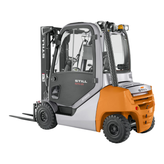
Overviews Overview Overview 73XX_003-001 Rotating beacon (variant) Drive axle Rear working spotlight (variant) Fork arms Rear lighting (variant) Fork carriage Driver's compartment Hydraulic connection for an attachment Exhaust pipe Lift mast Starter battery Front working spotlight (variant) Towing device Overhead guard Steering axle 57378011527 EN - 10/2020 - 04... -
Page 69: Driver's Compartment
Cup holder Steering wheel Driver's seat Mini-console Accelerator pedal Key switch Brake pedal Compartment Steering column adjustment lever Display/control unit "STILL Easy Control" Parking brake Operating devices Compartment and storage location for oper- ating instructions 57378011527 EN - 10/2020 - 04... -
Page 70: Shelves And Cup Holders
Overviews Shelves and cup holders NOTE The truck equipment may differ from the equipment shown. Shelves and cup holders WARNING Risk of accident as a result of objects that are not se- cure! Objects that are not safely stowed may fall into the footwell and slide between the pedals (3). -
Page 71: Operating Devices And Display Elements
Right-hand favourites bar Brightness sensor Lift height restriction The "STILL Easy Control" is a display-operat- ing unit that serves as an operating device for various truck functions, such as lighting or driving dynamics. It uses various symbols, val- ues and display messages to provide informa- tion about the status of the truck, e.g. -
Page 72: Operating Devices For Hydraulic And Driving Functions
– For information about the other display op- tions, see the original operating instructions entitled "STILL Easy Control display-operat- ing unit". NOTE Do not put a label over the brightness sen- sor (21) or cover it with anything. -
Page 73: Double Mini-Lever
Overviews Operating devices and display elements Double mini-lever Drive direction switch "F1" function key Cross lever "Attachments" "Lift mast" 360° lever Function key for the "5th function" Display field for the hydraulic functions Signal horn button 57378011527 EN - 10/2020 - 04... - Page 74 Overviews Operating devices and display elements NOTE In the dual-pedal version (variant), the drive ● direction switch (1) is used exclusively to activate the cruise control function (variant). The drive direction is selected exclusively via the pedals in the dual-pedal version. The authorised service centre can assign ●...
-
Page 75: Triple Mini-Lever
Overviews Operating devices and display elements Triple mini-lever Drive direction switch Signal horn button "Auxiliary hydraulics 1" operating lever "F1" function key "Auxiliary hydraulics 2" operating lever "Lift mast" 360° lever Function key for the "5th function" Display field for the hydraulic functions 57378011527 EN - 10/2020 - 04... - Page 76 Overviews Operating devices and display elements NOTE In the dual-pedal version (variant), the drive ● direction switch (1) is used exclusively to activate the cruise control function (variant). The drive direction is selected exclusively via the pedals in the dual-pedal version. The authorised service centre can assign ●...
-
Page 77: Quadruple Mini-Lever
Overviews Operating devices and display elements Quadruple mini-lever Drive direction switch Signal horn button "Tilt" operating lever "F1" function key "Auxiliary hydraulics 1" operating lever "Lift/lower" operating lever "Auxiliary hydraulics 2" operating lever Display field for the hydraulic functions Function key for the "5th function" 57378011527 EN - 10/2020 - 04... - Page 78 Overviews Operating devices and display elements NOTE In the dual-pedal version (variant), the drive ● direction switch (1) is used exclusively to activate the cruise control function (variant). The drive direction is selected exclusively via the pedals in the dual-pedal version. The authorised service centre can assign ●...
-
Page 79: Joystick 4Plus
Overviews Operating devices and display elements Joystick 4Plus 6210_003-087 Horizontal rocker button for the "3rd hydraul- LED for the clamp locking mechanism (var- ic function", tilting the lift mast iant) Symbols for the basic hydraulic functions Slider for the "4th hydraulic function", e.g. Pictograms for the 5th hydraulic function and side shift frame forwards/backwards for the clamp locking mechanism (variant) -
Page 80: Fingertip
Overviews Operating devices and display elements Fingertip Signal horn button Drive direction switch LED for the "5th function" "Lift/lower" operating lever Function key for the "5th function" "Tilt" operating lever LED for the "Clamp release" "F1" function key Operating lever for "Auxiliary hydraulics 1" LED for "F1"... -
Page 81: Travel Direction Selector And Indicator Module (Variant)
Overviews Operating devices and display elements Travel direction selector and indica- tor module (variant) The travel direction selector and indicator module is located on the steering column be- low the steering wheel. NOTE If the drive direction switch on the operating device is defective and the truck stops in a danger area, the drive direction selection lever on the travel direction selector and indicator... - Page 82 Overviews Operating devices and display elements 57378011527 EN - 10/2020 - 04...
-
Page 83: Operation
Operation... -
Page 84: Checks And Tasks Before Daily Use
Operation Checks and tasks before daily use Checks and tasks before daily use Visual inspections and function checking WARNING Risk of injury from falling off the truck! When climbing onto the truck, there is a risk of getting stuck or slipping and fall- ing. - Page 85 Operation Checks and tasks before daily use Component Course of action Check the area under the truck for leaking consum- Underside ables. Perform a visual inspection for integrity. Overhead guard, guard grille (variant) Check for secure mounting. Steps Make sure they are clean (free of ice, not slippery). Perform a visual inspection for integrity.
- Page 86 Operation Checks and tasks before daily use Component Course of action Perform a visual inspection for wear and damage. Make sure that only rims of the same type from the same manufacturer are fitted. Wheels, tyres In the event of uneven tyre wear, replace both tyres.
-
Page 87: Climbing In And Out Of The Truck
Operation Checks and tasks before daily use Climbing in and out of the truck WARNING Risk of injury when climbing in and out of the truck due to slipping, hitting yourself on parts of the truck or becoming stuck! If the footwell cover is very dirty or smeared with oil, there is a risk of slipping. - Page 88 Operation Checks and tasks before daily use To assist with climbing in and out of the truck, the footwell must be used as a step (5) and the handle (1) must be used for support. The post of the overhead guard (2) can also be used for support.
-
Page 89: Operating The Signal Horn
Operation Checks and tasks before daily use Operating the signal horn – Push the signal horn button (1). The signal horn sounds. NOTE The signal horn is used to warn people against imminent danger or to announce your intention to overtake. 57378011527 EN - 10/2020 - 04... -
Page 90: Driver's Cab
Operation Checks and tasks before daily use Driver's cab DANGER Risk of fatal injury in the event of falling from the truck if it tips over! In order to prevent the driver from sliding underneath the truck and being crushed if the truck tips over, a restraint system must be in place and must be used. -
Page 91: Checking The Brake System For Correct Function
Operation Checks and tasks before daily use NOTE Only approved types of tyre may be used; see chapter entitled "Tyres". – Check tyres (1) for wear or damage. Tyres must not be damaged or excessively worn. They must be worn evenly on both sides. - Page 92 Operation Checks and tasks before daily use Checking the service brake – Release the parking brake. – Depress the brake pedal (1). There must be a slight pedal clearance and then a noticeable pressure point at the brake. – Accelerate the unladen truck in a clear area.
- Page 93 Operation Checks and tasks before daily use WARNING There is no electric braking assistance when the key switch is switched off! Switching off the key switch will de-energise the en- tire electrical system. After this, the regenerative brake will not be available. CAUTION There is no power steering when the key switch is switched off!
-
Page 94: Checking The Steering System For Correct Function
Operation Checks and tasks before daily use Checking the electric brake DANGER Risk of accident due to reduced braking power! The regenerative brake may not be sufficient for emergency braking. – Always actuate the brake pedal (2) for emergency braking. -
Page 95: Function Checking Of The Automatic Mast Vertical Positioning Function (Variant)
Operation Checks and tasks before daily use Function checking of the automatic mast vertical positioning function (variant) CAUTION Risk of damage to property due to the lift mast collid- ing with racks or other objects! – Before using the "automatic mast vertical position- ing"... -
Page 96: Driver's Seats
Operation Driver's seats Driver's seats Adjusting the MSG 65/MSG 75 driv- er's seat WARNING Slipping of the seat poses a risk of accident during travel! If the driver's seat slips from the set position while driving, the seat position is unstable. This may result in unintentional actuation of the steering or operating devices and cause the truck or load to move in an uncontrolled fashion. - Page 97 Operation Driver's seats Moving the driver's seat – Lift the lever (1) and hold the lever in posi- tion. – Push the driver's seat into the desired posi- tion. – Release the lever. – Make sure that the driver's seat is engaged. 7094_003-006 Adjusting the seat backrest ...
- Page 98 Operation Driver's seats Adjusting the seat suspension NOTE The driver's seat can be adjusted to the driv- er's weight. To ensure optimum adjustment of the seat suspension, the driver must be sitting on the seat. NOTE The MSG 65/MSG 75 driver's seat is designed for people weighing between 45 kg and 170 kg.
- Page 99 Operation Driver's seats Adjusting the lumbar support (variant) The lumbar support can be adjusted to suit your own lumbar vertebrae. Adjusting the lum- bar support moves a convex support cushion into the upper or lower part of the backrest. –...
- Page 100 Operation Driver's seats Switching the seat heater (variant) on and off NOTE The seat heater only heats up when the seat heater is switched on and the seat base is oc- cupied. – Sit in the driver's seat. – Switch the seat heater (7) on or off using the switch.
-
Page 101: Adjusting The Armrest
Operation Driver's seats must be swivelled back into place for forward travel. To swivel back for forward travel: – Pull the lever (8) back and hold it in posi- tion. – Swivel the driver's seat to the left until it reaches the stop. -
Page 102: Longitudinal Horizontal Suspension (Variant)
Operation Driver's seats Longitudinal horizontal suspension (variant) If the driver's seat is equipped with the "longi- tudinal horizontal suspension" variant, impacts in the drive direction are damped by additional seat suspension. Longitudinal seat adjustment As with a standard driver's seat, the lever (1) ... -
Page 103: Seat Belt
Operation Driver's seats Seat belt DANGER Even when using an approved restraint system, there is some residual risk of the driver being injured if the truck tips over. This risk of injury can be reduced through the combined use of the re- straint system and the seat belt. - Page 104 Operation Driver's seats NOTE The buckle has a buckle switch (variant). In the event of an operating error or malfunction, the message SAFETY BELT appears in the display and operating unit, see the chapter en- titled "Display messages". – Pull the seat belt (3) smoothly out of the belt retractor and fasten closely around the body over the thighs.
- Page 105 Operation Driver's seats Releasing the seat belt – Push the red button (4) on the buckle (1). – Slowly guide the belt tongue back to the re- tractor by hand. NOTE Do not allow the seat belt to retract too quick- ly.
-
Page 106: Pre-Shift Check
Operation Pre-Shift Check Pre-Shift Check Description of the Pre-Shift Check (variant) The Pre-Shift Check is a guided dialogue in the display-operating unit. It also helps the driver conduct the necessary "visual inspec- tions and function checking" before everyday use. After the truck has been switched on, the driver must answer questions about the condi- tion of the forklift truck with "Yes"... -
Page 107: Process
The main display contains the message complete Pre-Shift Check, press This means that the Pre-Shift Check is still ac- tive and the truck functions are restricted. – To acknowledge the message, press the 6219_003-265_en softkey. -
Page 108: All Questions
Operation Pre-Shift Check – Switch on and check the function to be tes- ted, e.g. lighting. – Press the back button to go back to the Pre-Shift Check. – Answer the question based on the result of Pre-S the function check. The next question appears. - Page 109 Operation Pre-Shift Check Is the tyre pressure correct? Is the overhead guard visibly damaged? Is the entry area or footwell dirty or slippery? Are the windows clean and undamaged? Are the maintenance lids securely closed? Is the battery door/hood undamaged and securely closed? Is the battery lock present, undamaged and closed? Is the battery connection assembly dirty or damaged (e.g.
-
Page 110: Defining The Question Sequence
Operation Pre-Shift Check Defining the question sequence The questions for the Pre-Shift Check can be defined in a random sequence or in a fixed se- quence. The random sequence is advisable, because the questions are then read more consciously by the driver. This means that there is no rou- tine aspect. -
Page 111: Displaying The History
Operation Pre-Shift Check The Pre-Shift Check menu appears. – Press the softkey. Question sequence History Reset restriction Shift start Question sequence Fleet manager 6219_003-269_en Pressing the softkey allows fixed or random question sequences to be selected. The orange activation bar displays the current selection. - Page 112 Operation Pre-Shift Check – Press the softkey Service – Press the scroll keys until the Pre- menu appears. Shift Check – Press the softkey. Pre-Shift Check Message list Maintenance interval Version list Pre-Shift Check Calibration Fleet manager 6219_003-268_en 57378011527 EN - 10/2020 - 04...
-
Page 113: Defining The Shift Start
Operation Pre-Shift Check The Pre-Shift Check menu appears. – Press the softkey. History History Reset restriction Shift start Question sequence Fleet manager 6219_003-269_en The "Pre-Shift Check results" display opens. This display shows all checks and questions that have been answered with the date and Pre-Shift Check results time. - Page 114 Operation Pre-Shift Check – Activate the "Access authorisation for the fleet manager". – Press the softkey. Service – Press the scroll keys until the Pre- menu appears. Shift Check – Press the softkey. Pre-Shift Check Message list Maintenance interval Version list Pre-Shift Check Calibration...
- Page 115 Operation Pre-Shift Check The Pre-Shift Check menu appears. – Press the "Shift start" softkey. History Reset restriction Shift start Question sequence Fleet manager 6219_003-269_en In this menu, you can call up the shift to be defined and its start time. The orange activation bar indicates which shifts are activated.
- Page 116 Operation Pre-Shift Check In this menu you can define the shift start. – Enter the time using softkeys "0 to 9". – To , press the button. save Shift start 1 The shift start is now defined. The Pre-Shift Check is always requested from this shift start time.
-
Page 117: Resetting The Truck Restrictions
Operation Pre-Shift Check – Press the scroll button to deactivate the shift. – To confirm, press the button. Shift start 1 The time is shown in grey. The shift is deactivated. The display returns to the previous menu. There is no activation bar next to this shift. - Page 118 Operation Pre-Shift Check – Press the scroll keys until the Pre- menu appears. Shift Check – Press the softkey. Pre-Shift Check Message list Maintenance interval Version list Pre-Shift Check Calibration Fleet manager 6219_003-268_en The Pre-Shift Check menu appears. –...
- Page 119 Operation Pre-Shift Check A question pops up asking if you want to reset the truck restrictions. – To confirm, press the softkey. The full scope of the truck functions is now available. The display returns to the previous Reset the truck restrictions? The entry remains in the history menu.
-
Page 120: Driver Profiles
Operation Driver profiles Driver profiles Driver profiles (variant) This variant allows up to ten individual driver profiles to be created. The driver is greeted with the selected name after logging in. Once the softkey is pressed, the main display is shown. - Page 121 Operation Driver profiles equipped with these variants, drivers must se- lect their profiles manually. NOTE Access to the settings menu is only available if the truck is at a standstill and the parking brake is applied. If the parking brake is re- leased prematurely, the settings menu will close.
-
Page 122: Creating Driver Profiles
Operation Driver profiles The orange activation bar displays the current selection. – Press the softkey for the required driver profile. Guido The driver profile is active. The driver is gree- ted with the selected name the next time that Horst the truck is switched on. - Page 123 Operation Driver profiles – Press the soft- Driver profiles Driver profiles Truck information Display settings Configure favourites Truck settings 6219_003-293_en This menu provides storage space for saving ten driver profiles. – Press the softkey for the required storage location.
-
Page 124: Renaming Driver Profiles
Operation Driver profiles menu is displayed. Driver name – Use the softkeys to enter the desired name. – To confirm, press the button. Driver name The driver profile is active. The driver is gree- ted with the selected name after the next log- Any changes that drivers make to the settings Enter driver name while they are logged in are saved. - Page 125 Operation Driver profiles – Press the Rename driver profiles softkey. Driving programme Rename driver profiles 6219_003-298_en menu is displayed. Driver name – Use the softkeys to enter the desired name. – To confirm, press the button. Driver name Renaming by the fleet manager –...
- Page 126 Operation Driver profiles – Press the Manage driver profiles softkey. Lift height preselection Auxiliary hydraulics Change PIN codes Manage driver profiles On-board charger Fleet manager 6219_003-296_en – Press the Rename driver profiles softkey. Rename driver profiles Delete driver profiles Fleet manager 6219_003-297_en 57378011527 EN - 10/2020 - 04...
-
Page 127: Deleting Driver Profiles
Operation Driver profiles menu is displayed. Driver name – Use the softkeys to enter the desired name. – To confirm, press the button. Driver name Enter driver name Horst = Clear = abc -> ABC = Save = Cancel 6219_003-295_en Deleting driver profiles The fleet manager has access authorisation to... - Page 128 Operation Driver profiles – Press the Delete driver profiles softkey. Rename driver profiles Delete driver profiles Fleet manager 6219_003-297_en – Press the softkey for the driver profile to be deleted. The driver profile is deleted. Guido Horst Lisa Driver 4 Available storage position 5 6219_003-294_en...
-
Page 129: Switching On And Starting
Operation Switching on and starting Switching on and starting Engine preheating (variant) Function At ambient temperatures below the freezing point, a preheated engine is easier to start. The starter battery is protected. The engine consumes less fuel. 230 V In trucks with the engine preheating function, a heating element (1) that is connected to a built-in plug (3) in the engine compartment is... -
Page 130: Switching On The Key Switch And Starting The Engine
Operation Switching on and starting – Plug the connecting cable (2) into the built- in socket (3). – Plug the connecting plug (4) into an earthed 230V socket. – Preheat the engine for at least 2 hours. The preheating time may be longer than this depending on the ambient temperature. - Page 131 Operation Switching on and starting WARNING Before switching on the key switch, all visual inspec- tions and function checking must be carried out with- out any defects being identified. – Perform the visual inspections and function check- ing. – Do not operate the truck if defects have been de- tected;...
-
Page 132: Access Authorisation With Pin Code (Variant)
– Stop the engine immediately. 7071_003-101 – Check the engine oil level and top up if necessary – If the message still appears, contact the author- ised service centre. – Please note the information in the chapter entitled "Malfunctions". - Page 133 Operation Switching on and starting NOTE We recommend that the fleet manager changes this PIN code using their access au- thorisation. See also the section entitled "Ac- cess authorisation for the fleet manager (var- iant)". When the key switch is switched on, the ...
-
Page 134: Access Authorisation For The Fleet Manager (Variant)
Operation Switching on and starting – Press the softkey. Service – Press the scroll keys until the menu appears. Change PIN codes – Press the softkey. Change PIN codes Calibration – Follow the instructions on the display. Relieve hydraulics Shock sensor Change password (access auth.) Change PIN codes... - Page 135 Operation Switching on and starting NOTE Access to the settings menu is only available if the truck is at a standstill and the parking brake is applied. If the parking brake is released prematurely, the settings menu will close. – Stop the truck. –...
- Page 136 Operation Switching on and starting The message Access authorisation appears. fleet manager granted – To confirm, push the Softkey "Access authorisation for the fleet manager" is activated. The display returns to the settings Fleet manager menu. access authorisation If the password entered was incorrect, the granted message is dis-...
- Page 137 Operation Switching on and starting – Press the scroll keys until the Change password (access menu appears. auth.) – Press the Version list Change password (ac- softkey. cess auth.) – Follow the instructions on the display. Calibration Changing the PIN code for the driver Relieve hydraulics –...
- Page 138 Operation Switching on and starting – Press the scroll keys until the menu appears. Change PIN codes – Press the softkey. Change PIN codes Calibration – Follow the instructions on the display. Relieve hydraulics Shock sensor Change password (access auth.) Change PIN codes Fleet manager 6219_003-276_en...
-
Page 139: Lighting
– To access this sub-menu, push the but- Symbols for the lighting and their meanings Parking light Headlights Hazard warning system Rotating beacon STILL SafetyLight Warning zone light Front working spotlights Rear working spotlights Roof working spotlights Only the symbols of the lighting devices that are installed in the truck can be selected. -
Page 140: Driving Lights
Operation Lighting Driving lights – To switch on the parking light (1), push the associated Softkey on the display-operating unit. The front side lights and the tail lights light up. – To switch on the driving light (2), press the associated Softkey on the display-operating unit. -
Page 141: Working Spotlights
Operation Lighting Working spotlights Front and rear working spotlights – To switch on the front working spot- lights (3), push the associated Softkey on the display-operating unit. The front working spotlights light up. – To switch off the front working spot- lights (3), push the Softkey again. -
Page 142: Working Spotlight For Reverse Travel (Variant)
Operation Lighting Working spotlight for reverse travel (variant) In this equipment variant, a working spotlight for reverse travel is fitted on the rear of the overhead guard and provides optimum illumi- nation of the roadway during reverse travel. – Press the softkey. - Page 143 Operation Lighting – To switch on the left or right turn indicator, move the lever (1) to the desired direction. 6219_003-098 The turn indicators and the turn indicator dis- play (2) or (3) on the display-operating unit flash. 08:20 –...
-
Page 144: Hazard Warning System
Operation Lighting Hazard warning system Switching the hazard warning system on and off is different for trucks with and without the StVZO (German Road Traffic Licensing Regu- lations) variant. – To switch on the hazard warning system, push the associated Softkey on the display- operating unit. -
Page 145: Stvzo Equipment
This softkey is used to switch off all light- ing devices that are not permitted on roads subject to the StVZO. This relates to the following variants of lighting equipment: STILL SafetyLight ● Warning zone light ● Working spotlight ●... -
Page 146: Rotating Beacon
Danger of damage to eyes from looking into the STILL SafetyLight. Do not look into the STILL SafetyLight. The STILL SafetyLight is a visual warning unit designed to enable early detection of trucks in driving areas with low visibility (such as drive lanes, high racks), as well as at blind junc- tions. - Page 147 Operation Lighting – To do so, push the Softkey NOTE If the truck is to be operated on public roads, the STILL SafetyLight must be switched off. 57378011527 EN - 10/2020 - 04...
-
Page 148: Blue-Q Efficiency Mode
Blue-Q has no influence on: Climbing capability ● Pulling force ● Braking characteristics ● NOTE If no other energy mode is selected, STILL- Classic is automatically active. No pictogram is displayed for STILL-Classic. 57378011527 EN - 10/2020 - 04... -
Page 149: Switching Blue-Q On And Off
Operation Blue-Q efficiency mode Switching Blue-Q on and off – To switch on Blue-Q efficiency mode, push the softkey The Blue-Q symbol appears on the dis- play/operating unit and Blue-Q efficiency mode is switched on. – To switch off Blue-Q efficiency mode, push the associated softkey again. -
Page 150: Switching Off Additional Consumers
Operation Blue-Q efficiency mode Switching off additional consumers If the Blue-Q efficiency mode is activated, the controller switches off various additional con- sumers after a few seconds in certain condi- tions. The additional consumers available de- pend on the truck equipment. The following ta- ble shows the conditions that cause additional consumers to be switched off. -
Page 151: Still Classic And Sprint Mode
Operation Blue-Q efficiency mode STILL Classic and sprint mode Drive modes influence the driving perform- ance and the lifting performance of the electric drive. Two different drive modes are available: STILL Classic This mode is active after the truck has been switched on. - Page 152 Operation Blue-Q efficiency mode If the truck is automatically switched off, sprint mode can then only be switched on again if the following conditions are met: The temperatures of the drive units and the ● energy supply are not too high The truck has been restarted.
-
Page 153: Driving
Operation Driving Driving Safety regulations when driving Driving conduct The driver must follow the public rules of the road when driving in company traffic. The speed must be appropriate to the local conditions. For example, the driver must drive slowly around corners, in tight passageways, when driving through swing-doors, at blind spots, or on uneven surfaces. - Page 154 There is a risk of acci- dent! – Do not use devices during travel or when handling loads. – Set the volume so that warning signals can still be heard. WARNING In areas where use of mobile phones is prohibited, use of a mobile phone or radio telephone is not per- mitted.
-
Page 155: Roadways
The required aisle widths depend on the di- mensions of the load. For pallets, these are: Aisle width [mm] With pallet With pallet Model Type 1000x1200 800x1200 crosswise lengthwise RX70-20/600 7394 3963 4163 RX70-25 7395 3963 4163 RX70-25/600 7396 4047 4247... - Page 156 Operation Driving The truck is approved for driving on the follow- ing ascending and descending gradients: Maximum gradient [%] Model Type With a load Without a load RX70-20/600 7394 RX70-25 7395 RX70-25/600 7396 RX70-30 7397 RX70-30/600 7398 RX70-35 7399 The stated values are used only to compare the performance of trucks in the same catego- ry.
- Page 157 Operation Driving The structural design of drains, level crossings and other similar facilities must enable them to be driven over with as few bumps as possible. If necessary, use ramps to compensate for un- even roadways. Note the load capacity of manhole covers, drain covers etc.
-
Page 158: Selecting Drive Programmes 1 To 3
Operation Driving Selecting drive programmes 1 to 3 The truck has three drive programmes with different preset driving and braking character- istics. The basic principle is that the higher the number of the drive programme selected, the greater the driving dynamics. The drive programme is selected using the display-operating unit under the "Drive"... -
Page 159: Selecting Drive Programme A Or B
Operation Driving Selecting drive programme A or B The truck has two driving programmes for per- sonalised handling and braking characteris- tics. Unlike the fixed drive programmes "1 to 3", the programs "A" and "B" can be configured. The procedure for this is described in the following section. - Page 160 Operation Driving – Press the associated Softkey for drive programme A drive programme B The process for configuring the drive pro- grammes using "drive programme A" is ex- plained here. The menu Set drive programme A appears. The following parameters can be set: ●...
-
Page 161: Selecting The Drive Direction
Operation Driving Selecting the drive direction The drive direction of the truck must be selec- ted using the drive direction switch/drive direc- tion selection lever before attempting to drive. The method of actuating the drive direction switch/drive direction selection lever depends on the operating devices that are fitted in the truck. -
Page 162: Actuating The Drive Direction Switch With The Mini-Lever Version
Operation Driving Actuating the drive direction switch with the mini-lever version – For the "forwards" drive direction, push the drive direction switch (1) forwards. – For the "backwards" drive direction, pull the drive direction switch (1) backwards. NOTE If the drive direction switch (1) is defective and the truck stops in a danger area, the drive di- rection selection lever on the travel direction selector and indicator module (variant) can be... -
Page 163: Actuating The Drive Direction Switch, Mini-Console Version
Operation Driving Actuating the drive direction switch with the Fingertip version – For the "forwards" drive direction, push the drive direction switch (1) forwards. – For the "backwards" drive direction, pull the drive direction switch (1) backwards. NOTE If the drive direction switch (1) is defective and the truck stops in a danger area, the drive di- rection selection lever on the travel direction selector and indicator module (variant) can be... - Page 164 Operation Driving – Observe the information in the chapter enti- tled "Safety regulations when driving". The driver's seat is equipped with a seat switch. This seat switch checks whether the driver's seat is occupied. If the driver's seat is not occupied or if the seat switch is malfunc- tioning, the truck cannot be moved and all lift- ing functions are locked.
- Page 165 If the truck still cannot be operated, park the truck securely and con- tact the authorised service centre.
-
Page 166: Starting Drive Mode, Dual Pedal Version (Variant)
Operation Driving Starting drive mode, dual pedal ver- sion (variant) DANGER Risk to life if the truck rolls away or tips over! – Sit on the driver's seat. – Fasten the seat belt. – Activate the available restraint systems. – Observe the information in the chapter enti- tled "Safety regulations when driving". - Page 167 Operation Driving The indicator for the selected drive direction ("forwards" (1) or "backwards" (2)) lights up on the display-operating unit. NOTE Depending on the equipment, one of the equipment variants activates as a warning for reverse travel: Signal tone ●...
-
Page 168: Operating The Service Brake
If the truck still cannot be operated, park the truck securely and con- tact the authorised service centre. -
Page 169: Actuating The Electric Parking Brake
Operation Driving – Brake the truck by releasing the accelerator pedal (1). – If the braking effect is inadequate, brake us- ing the service brake (2) as well. Zero braking (variant) DANGER Risk of accident! Trucks with zero braking (variant) are not braked when the accelerator pedal is released. - Page 170 – Press the push button (1) to release the parking brake. The traction motor keeps the truck at a stand- still. Manually actuating the electric parking brake when the truck is stationary Applying the parking brake manually – Press the push button (1).
- Page 171 Operation Driving Automatically triggered actuation when the truck is stationary Cause Effect The electric parking brake will make a noise The driver's seat is vacated. when it is applied. The LED (2) lights up. The electric parking brake is immediately ap- plied with an audible sound.
- Page 172 Operation Driving NOTE If the drive unit fails, the truck can be braked by pressing the push button (1). The truck brakes more strongly if the push button (1) is pressed and held or pressed several times. The electric parking brake cannot be released by actuating the accelerator pedal.
-
Page 173: Malfunctions In The Electric Parking Brake
A possible cause of the malfunction is that the parking brake cannot determine whether the 6219_003-006_V2 truck is stationary or still in motion. The follow- ing section describes how to actuate the park- ing brake when it is faulty: Actuating a faulty parking brake when the... - Page 174 Operation Driving – Press the push button (1) several times in succession so that the push button is actu- ated for a total of 5 seconds. The parking brake is applied with an audible sound. After the push button is released, the parking brake should not make any further sounds;...
- Page 175 Operation Driving Activation and intervention by the "Safe parking" function Cause Effect The following message appears in the display: Parking brake cannot be applied. The driver's seat is vacated. The electric park- - To confirm the message, press the Soft- ing brake cannot be applied or previously could key.
- Page 176 Operation Driving Message: Parking brake cannot be applied If the truck control unit detects a malfunction in the parking brake, the truck cannot be switch- ed off. ● Parking brake cannot be message appears on the dis- applied play-operating unit. The LED (2) on the push button (1) flashes.
-
Page 177: Steering
Operation Driving Steering DANGER If the hydraulics fail, there is a risk of accident as the steering characteristics have changed. – Do not operate the truck if it has a defective steer- ing system. – Steer the truck by turning the steering wheel (1) accordingly. -
Page 178: Driving On Ascending And Descending Gradients
Operation Driving Driving on ascending and descend- ing gradients DANGER Danger to life! Driving on ascending and descending gradients car- ries special dangers! – Always follow the instructions below. – On ascending and descending gradients, the load must be carried facing uphill. –... -
Page 179: Speed Reduction When The Fork Carriage Is Raised (Variant)
Operation Driving Speed reduction when the fork car- riage is raised (variant) If the truck is equipped with this variant, the driving speed is automatically reduced to 5 km/h (forwards and backwards) from a lift height of more than 500 mm. If the fork carriage is lowered below this lift height again, the driving speed limitation is de- activated. -
Page 180: Cruise Control (Variant)
Operation Driving 10 seconds before the response time elapses, the following message appears: Switch off combustion engine The following driver responses are possible: Switch off Switch off – No response. combustion combustion engine engine The engine switches off after 10 seconds. –... - Page 181 Operation Driving When the cruise control function is activated, the speed can be saved when driving forwards at a speed of at least 6.0 km/h by pressing a button and the truck can continue driving with- out the accelerator pedal being actuated. The pictogram for operating the cruise con- trol function is located on the operating device...
- Page 182 Operation Driving Activating cruise control function WARNING Risk of accident from failing to adjust speed! Driving at excessive speeds can cause accidents, e.g. the truck could tip over when cornering. – Adjust speed along the entire distance being trav- elled –...
- Page 183 Operation Driving When the cruise control function is deactiva- ted, the symbol is greyed out. NOTE The easiest way to deactivate the cruise con- trol function is to touch the accelerator pedal. The following actions deactivate the cruise control function: Actuating the foot brake ●...
-
Page 184: Parking
Operation Parking Parking Parking the truck securely and switching it off DANGER Risk of fatal injury from being run over if the truck rolls away! – The truck must not be parked on a slope. – In emergencies, secure the truck us- ing wedges on the side facing down- hill. -
Page 185: Wheel Chock (Variant)
Operation Parking Wheel chock (variant) The wheel chock (variant) is used to prevent the truck from rolling away on a slope. – Lift handle (2) on the support mounting. – Remove wheel chock (1) from the support mounting. – Push the wheel chock under a front axle wheel on the side facing the downhill slope. -
Page 186: Lifting
Operation Lifting Lifting Lifting system variants The movement of the fork carriage and the lift mast heavily depends on the following equip- ment: The lift mast with which the truck is equip- ● ped, see C hapter "Types of lift mast", ⇒ ... - Page 187 Operation Lifting The "automatic mast vertical positioning" as- sistance system consists of the following indi- vidual functions: Display of the "Automatic mast vertical posi- ● tioning" feature Automatic startup of the "Automatic mast ● vertical position" feature The truck can also be equipped with only the "mast tilt angle display"...
-
Page 188: Types Of Lift Mast
Operation Lifting Types of lift mast One of the following lift masts may be installed in the truck: Telescopic mast During lifting, the lift mast rises over the outer lift cylinders, bringing the fork carriage with it via the chains (fork carriage rises twice as fast as the inner lift mast). -
Page 189: Malfunctions During Lifting Mode
Operation Lifting Triplex lift mast (variant) During lifting, the inner lift cylinder moves up to free lift (3), and then the outer lift cylinders raise the inner lift mast up to the max. height (2). DANGER Risk of accident due to collision of the lift mast or load with low ceilings or entrances. -
Page 190: Hydraulic Blocking Function
Operation Lifting Load chains not under tension DANGER Danger caused by a falling load! – Make sure that the chain(s) does (do) not become slack when lowering the load. Slack chains can, for instance, result from: Resting the fork carriage or the load on the ●... -
Page 191: Lifting System Operating Devices
Operation Lifting – Sit down on the driver's seat. All the relevant functions of the working hy- draulics will be available again. NOTE If it is not possible to release the block on the hydraulics when the load is raised because of a technical fault, the load must be lowered us- ing the "emergency lowering"... -
Page 192: Controlling The Lifting System Using A Double Mini-Lever
Operation Lifting Controlling the lifting system using a double mini-lever DANGER Reaching into or climbing between moving parts of the truck (e.g. lift mast, sideshifts, working equip- ment, load carrying devices etc.) can lead to seri- ous injury or death and is therefore prohibited. –... - Page 193 Operation Lifting – Move the "lift mast" 360° lever (4) in the di- rection of the arrow (C). To tilt the lift mast backwards: – Move the "lift mast" 360° lever (4) in the di- rection of the arrow (D). Movements of the lifting system and meanings of the pictograms Lowering...
-
Page 194: Controlling The Lifting System Using A Triple Mini-Lever
Operation Lifting Controlling the lifting system using a triple mini-lever DANGER Reaching into or climbing between moving parts of the truck (e.g. lift mast, sideshifts, working equip- ment, load carrying devices etc.) can lead to seri- ous injury or death and is therefore prohibited. –... - Page 195 Operation Lifting – Move the "lift mast" 360° lever (4) in the di- rection of the arrow (C). To tilt the lift mast backwards: – Move the "lift mast" 360° lever (4) in the di- rection of the arrow (D). Movements of the lifting system and meanings of the pictograms Lowering...
-
Page 196: Controlling The Lifting System Using A Quadruple Mini-Lever
Operation Lifting Controlling the lifting system using a quadruple mini-lever DANGER Reaching into or climbing between moving parts of the truck (e.g. lift mast, sideshifts, working equip- ment, load carrying devices etc.) can lead to seri- ous injury or death and is therefore prohibited. –... -
Page 197: Controlling The Lifting System Using The Joystick 4Plus
Operation Lifting Movements of the lifting system and meanings of the pictograms Lowering Lifting Tilting forwards Tilting backwards Controlling the lifting system using the Joystick 4Plus DANGER Reaching into or climbing between moving parts of the truck (e.g. lift mast, sideshifts, working equip- ment, load carrying devices etc.) can lead to seri- ous injury or death and is therefore prohibited. - Page 198 Operation Lifting Tilting the lift mast To tilt the lift mast forwards: – Tilt the horizontal rocker button (2) to the left (C). To tilt the lift mast backwards: – Tilt the horizontal rocker button (2) to the right (D). 6210_003-090 7312_003-022_V2 57378011527 EN - 10/2020 - 04...
- Page 199 Operation Lifting Fork carriage sideshift To move the fork carriage to the left: – Push the Joystick 4Plus (1) to the left (E). To move the fork carriage to the right: – Push the Joystick 4Plus (1) to the right (F). NOTE The symbols on the Joystick 4Plus indicate the direction of movement of the lift mast or...
- Page 200 Operation Lifting Controlling the lifting system using the Fingertip DANGER Reaching into or climbing between moving parts of the truck (e.g. lift mast, sideshifts, working equip- ment, load carrying devices etc.) can lead to seri- ous injury or death and is therefore prohibited. –...
-
Page 201: Fork Wear Protection (Variant)
Operation Lifting Movements of the lifting system and meanings of the pictograms Lowering Lifting Tilting forwards Tilting backwards Fork wear protection (variant) The "fork wear protection" variant ensures that the fork arms do not touch the ground. The fork arms are protected against wear and the building floor is protected against damage. - Page 202 Operation Lifting WARNING There is a risk of injury when changing the fork arms; the weight of the fork arms could cause them to fall on your legs, feet or knees. The space to the left and right of the fork is a danger area. –...
- Page 203 Operation Lifting Removal – Select a pallet corresponding to the fork arm size. – Set down the pallet next to the fork carriage on the side chosen for removal. – Lift the fork carriage until the fork arms are approx.
-
Page 204: Fork Extension (Variant)
Operation Lifting NOTE If the truck is equipped with the "load meas- urement" comfort feature, a "zero adjustment of the load measurement" must always be performed after the fork arms have been changed. Otherwise, correct load measurement cannot be guaranteed. Fork extension (variant) DANGER There is a risk of being run over if the truck rolls... - Page 205 Operation Lifting Attachment DANGER Risk to life from falling load! At least 60% of the length of the fork extension must lie on the fork arm. A maximum 40% overhang over the fork arm end is permissible. The fork extension must also be secured against slipping from the fork arm.
-
Page 206: Operation With Reversible Fork Arms (Variant)
Operation Lifting Operation with reversible fork arms (variant) DANGER Risk to life from falling load! Standard fork arms are not structurally designed for reverse operation. If this instruction is not observed, it can lead to material failure and the load falling. –... - Page 207 Operation Lifting Reversible fork arms (1) can be used to reach an additional lift height. The reversible fork arms are installed on the fork carriage in the same manner as standard fork arms. Loads may be lifted on and beneath the reversible fork arms.
-
Page 208: Handling Loads
Operation Handling loads Handling loads Safety regulations when handing loads The safety regulations for handling loads are shown in the following sections. DANGER There is a risk to life caused by falling loads or if parts of the truck are being lowered. –... -
Page 209: Before Taking Up Load
Operation Handling loads Before taking up load Load capacity The load capacity indicated for the truck on the capacity rating plate may not be excee- ded. The load capacity is influenced by the load centre of gravity and the lift height as well as by the tyres, if applicable. - Page 210 Operation Handling loads Example Weight of load to be lifted: 880 kg (3) Load distance from fork back: 500 mm (1) Permitted lift height: 5230 mm (2) WARNING Risk of accident from the truck losing stability! The permissible load of the attachments (variant) 5230 and the reduced lifting capacity of the combination of truck and attachment must not be exceeded.
-
Page 211: Load Measurement (Variant)
Operation Handling loads Load measurement (variant) Knowing the weight of the load to be transpor- ted gives the driver greater security. If the truck is equipped with the "load measurement" assistance system, the weight of the lifted load is measured and displayed in the display-op- erating unit (1). -
Page 212: Picking Up Loads
Operation Handling loads Picking up loads To make sure that the load is securely suppor- ted, it must be ensured that the fork arms are sufficiently far apart and are positioned as far as possible under the load. If possible, the load should rest on the back of the fork. -
Page 213: Transporting Pallets
Operation Handling loads included are the areas where loads could fall or working equipment could fall or be lowered. DANGER Risk of injury! – Do not step on the fork. DANGER Risk of injury! – Do not step under the raised forks. DANGER People may be injured in the danger area of the truck! -
Page 214: Transporting Suspended Loads
Operation Handling loads Transporting suspended loads Before transporting suspended loads, consult the national regulatory authorities (in Germa- ny, the employer's liability insurance associa- tions). National regulations may place restrictions on these operations. Contact the relevant authori- ties. DANGER Suspended loads that begin to swing can result in the following risks: Impaired braking and steering action ●... -
Page 215: Picking Up A Load
Operation Handling loads DANGER Risk of accidents! When transporting hanging loads, never perform or end driving and load movements abruptly. Never drive on slopes with a suspended load. Transporting containers holding fluids as hanging loads is not permitted. Picking up a load DANGER There is a risk to life caused by a falling load or if parts of the truck are being lowered. - Page 216 Operation Handling loads – Position the forks. – Set the lift mast to vertical. – Lift the fork carriage to the stacking height. CAUTION Risk of component damage! Ensure that the rack and load do not become dam- aged when inserting the fork into the rack. 6210_800-006 –...
- Page 217 Operation Handling loads – Lift the fork carriage until the load is resting entirely on the fork. DANGER Risk of accident! – Beware of any people in the danger area. – Ensure that the roadway behind you is clear. DANGER Due to the risk of tipping, never tilt the lift mast with a raised load!
-
Page 218: Transporting Loads
Operation Handling loads – Tilt the lift mast backwards. The load can be transported. 5060_003-101 Transporting loads NOTE Observe the information in the chapter entitled "Safety regulations when driving". DANGER The higher a load is lifted, the less stable it be- comes. -
Page 219: Setting Down Loads
Operation Handling loads – Drive slowly and carefully round corners! NOTE Observe the information in the chapter entitled "Steering". – Always accelerate and brake gently! NOTE Observe the information in the chapter entitled "Operating the service brake". 6210_800-013 – Never drive with a load protruding to the ... - Page 220 Operation Handling loads WARNING Risk of accident from a falling load! If the fork or the load remains suspended during low- ering, the load may fall. – When removing from stock, move the truck far enough back so that the load and the fork can be lowered freely.
-
Page 221: Shake Function (Variant)
Operation Handling loads Shake function (variant) NOTE The shake function is intended only for short- term use, as it reduces the service life of the load chains due to the increased loading on them. Description The shake function of the hydraulics makes it easier for the driver to perform tasks such as emptying containers of bulk material. - Page 222 Operation Handling loads NOTE After the function has been activated, the driv- er has two seconds to start the shaking. If the two seconds elapse without the shake function being used, the shake function is deactivated again. WARNING The shake function remains active for two seconds following activation.
- Page 223 Operation Handling loads Double mini-lever: – Move the 360° lever (2) back and forth be- tween positions (A) and (B) four times. Then continue to move the component in the same way. Triple mini-lever: – Move the 360° lever (3) back and forth be- tween positions (A) and (B) four times.
-
Page 224: Driving On Lifts
Operation Handling loads Fingertip: – Move the operating lever (5) back and forth four times. Then continue to move the com- ponent in the same way. Driving on lifts The driver may only use this truck on lifts with a sufficient rated capacity and for which the operating company has been granted authori- sation. -
Page 225: Driving On Loading Bridges
Operation Handling loads Determining the actual total weight – Park the truck securely. – Determine the unit weights by reading the truck nameplate and, if necessary, the at- tachment (variant) nameplate and, if neces- Type-Modèle-Typ / Serial no.-No. de série-Serien-Nr. / year-année-Baujahr sary, by weighing the load to be lifted. - Page 226 Operation Handling loads Determining the actual total weight – Park the truck securely. – Determine the unit weights by reading the truck nameplate and, if necessary, the at- tachment (variant) nameplate and, if neces- Type-Modèle-Typ / Serial no.-No. de série-Serien-Nr. / year-année-Baujahr sary, by weighing the load to be lifted.
-
Page 227: Particle Filter System
Operation Particle filter system Particle filter system Particle filter - Function DANGER Risk to health from exhaust gases! Exhaust gases from internal combustion engines are harmful to your health. In particular, the soot particles con- tained in the diesel exhaust gas can cause cancer. Allowing the internal combustion engine to idle rep- resents a risk of poisoning from the CO, CH and components contained in the exhaust gas. -
Page 228: Particle Filter - Parked Regeneration
Operation Particle filter system exhaust gas temperatures may not be reached. If excessively low exhaust gas tem- peratures prevail, regeneration will not take place. If regeneration does not take place, the soot filtered out of the exhaust gas accumu- lates in the particle filter. If the particle filter becomes clogged, parked regeneration of the particle filter must be performed. - Page 229 1000 operating hours. The message Stand- still regeneration required ap- pears on the display. Parked regeneration must be performed. 57378011527 EN - 10/2020 - 04...
- Page 230 Operation Particle filter system Parked regeneration - rules of behav- iour As very hot exhaust gases are generated dur- ing parked regeneration of the particle filter, the following rules of behaviour must be ob- served: WARNING There is a risk of fire and burns during parked regen- eration due to very hot exhaust gases! During parked regeneration, high temperatures occur in the particle filter, in the exhaust system and in the...
- Page 231 Operation Particle filter system When parked regeneration starts, the mes- sage appears on the dis- Block truck? play-operating unit.. If the driver presses the "No" Softkey, the message Do not leave truck unat- appears on the display-operating tended unit. If the driver presses the "Yes" Softkey, the block is activated via the "access authorisation with PIN code"...
- Page 232 Operation Particle filter system Starting parked regeneration automati- cally NOTE The truck is equipped with a blocking function in connection with parked regeneration. This means that a block on the truck operation may be active after parked regeneration. An active block prevents the operation of the truck.
- Page 233 Operation Particle filter system The display changes to the status display shown for parked regeneration. The symbol Standstill regeneration Standstill regeneration (2) appears. in progress. in progress. The following messages (3) appear: Do not Do not switch off the engine switch off the engine ●...
- Page 234 – Press the Softkey NOTE If the soot accumulation is below 105%, the process is cancelled. The message Stand- still regeneration not required appears on the display-operating unit. The display changes to the status display shown for parked regeneration. The symbol...
- Page 235 Operation Particle filter system out and the message Regeneration appears. completed The main display is shown on the display. Op- erational readiness is restored. Aborting parked regeneration Parked regeneration can be aborted for the following reasons: Manually, via the display-operating unit ●...
- Page 236 Operation Particle filter system Automatic aborting triggered by release of the parking brake If the parking brake is released during parked regeneration, parked regeneration is aborted. The message Standstill reg. abor- appears. Parked regeneration must be restarted. – Apply the parking brake. –...
-
Page 237: Messages About Parked Regeneration
Operation Particle filter system Messages about parked regeneration The driver is informed of the need for a parked regeneration by means of corresponding mes- sages on the display-operating unit before parked regeneration is due. Shown on display Cause/action The particle filter is not saturated with soot. The last parked regeneration was less than 1000 Standstill regeneration not re- operating hours ago. - Page 238 Operation Particle filter system Regeneration was interrupted due to an error. The parking brake was released during parked regeneration. Apply the parking brake and restart regenera- tion. If the message appears more than twice in suc- Parked regeneration error cession without the parking brake being re- leased during parked regeneration, there may be a malfunction in the internal combustion en- gine.
-
Page 239: Attachments
Fitting attachments If the truck is equipped with an integrated at- tachment (variant) at the factory, the specifica- tions in the STILL operating instructions for in- tegrated attachments must be observed. If attachments are fitted at the place of use,... - Page 240 Operation Attachments DANGER There is risk to life caused by a falling load! Attachments that hold the load by exerting pressure on it (e.g. clamps) must be controlled additionally by a second operating function (lock) that is actuated to prevent an unintentional release of the load. If such an attachment is retrofitted, a second operat- ing function for actuation must also be retrofitted.
-
Page 241: Depressurising The Hydraulic System
Operation Attachments Load capacity with attachment The permissible load capacity of the attach- ment and the allowable load (load capacity and load moment) of the truck must not be ex- ceeded by the combination of attachment and payload. The specifications of the manufactur- er and supplier of the attachment must be complied with. - Page 242 Operation Attachments – Actuate the operating levers for controlling the hydraulic functions once in the direc- tions of the arrows as far as the end posi- tions. The hydraulic circuits of the basic functions are now depressurised. Depressurising the hydraulic circuits for the "5th hydraulic function"...
- Page 243 Operation Attachments Special feature for clamping attach- ments NOTE If a clamping attachment is fitted, please ob- serve the following: Depressurising the hydraulic circuit for ● clamping attachments is performed in the same way as opening and closing the clamp. Loosen the clamp locking mechanism;...
-
Page 244: General Instructions For Controlling Attachments
Operation Attachments General instructions for controlling attachments The way in which attachments (variant) are controlled depends on the operating devices included in the truck's equipment. Essentially, a distinction is drawn between: Double mini-lever ● Double mini-lever and 5th function (var- ●... -
Page 245: Attachment Example For The Connection Of The Auxiliary Hydraulics
Operation Attachments NOTE All the attachments described fall into the cat- egory of equipment variants. Please see the respective operating instructions for an exact description of the respective movements/ actions of the attachment fitted. With fleet manager access authorisation (var- iant), the fleet manager can adjust the speed of the auxiliary hydraulics for attachments. -
Page 246: Adjusting The Hydraulic Speed For Attachments
Operation Attachments connection for a switch valve that is not shown here. NOTE If one switch valve is used, the auxiliary hy- draulic functions 1 & 3 and 2 & 4 that are sup- plied by this switch valve cannot be operated simultaneously. - Page 247 Operation Attachments This menu lists all the available hydraulic axles for attachments. – Refer to the operating instructions of the at- tachment to determine which hydraulic axle Hydraulic axle 1 is occupied by the attachment. The authorised service centre will help you de- Hydraulic axle 2 termine the axles.
- Page 248 Operation Attachments Locking the flow rate You can also lock the hydraulic oil flow rate in full. – To do this, push the "Deactivate auxiliary hydraulics" softkey The hydraulic oil flow rate for this hydraulic axle is locked. Setting the return flow rate separately Depending on the attachment, the return flow rate may need to be set separately.
-
Page 249: Controlling Attachments Using A Double Mini-Lever
Operation Attachments Controlling attachments using a double mini-lever In this version, the attachments (variant) are controlled using the "attachments" cross lev- er (1). The adhesive label bearing the picto- grams for the hydraulic functions (2) is affixed at the designated point. –... - Page 250 Operation Attachments NOTE The pictograms are affixed according to the attachment fitted at the factory. If an attach- ment with different functions is fitted, the au- thorised service centre must check that the pictograms bear the correct representation and must change them if necessary. Clamp locking mechanism ...
-
Page 251: Controlling Attachments Using The Double Mini-Lever And The 5Th Function
Operation Attachments Controlling attachments using the double mini-lever and the 5th func- tion NOTE For technical reasons, clamping attachments must not be controlled via the "5th function". The function key for the "5th function" (3) and the cross lever (1) are used to control the "5th function". - Page 252 Operation Attachments Example using the pictograms for configura- tion (1): If the "attachments" cross lever (1) is moved in the direction of the arrow (A), the fork is exten- ded. If the function key for the "5th function" (3) is actuated and the "attachments"...
-
Page 253: Controlling Attachments Using A Triple Mini-Lever
Operation Attachments Controlling attachments using a tri- ple mini-lever In this version, the attachments (variant) are controlled using the operating levers (1, 2). The adhesive label bearing the pictograms for the hydraulic functions (3) for the operating lever (2) and the adhesive label (4) for the op- erating lever (1) are affixed at the designated points. - Page 254 Operation Attachments Picto- Attachment function gram Tip shovel over Tip shovel back NOTE The pictograms are affixed according to the attachment fitted at the factory. If an attach- ment with different functions is fitted, the au- thorised service centre must check that the pictograms bear the correct representation and must change them if necessary.
-
Page 255: Controlling Attachments Using The Triple Mini-Lever And The 5Th Function
Operation Attachments Controlling attachments using the triple mini-lever and the 5th function NOTE For technical reasons, clamping attachments must not be controlled via the "5th function". The function key for the "5th function" (2) and the operating lever (1) are used to control the "5th function". - Page 256 Operation Attachments Example using the pictograms for configura- tion (1): If the operating lever (1) is moved in the direc- tion of the arrow (E), the sideshift moves to the left. If the function key for the "5th function" (2) is actuated and the operating lever (1) is moved in the direction of the arrow (E), the fork arms open.
-
Page 257: Controlling Attachments Using A Quadruple Mini-Lever
Operation Attachments Controlling attachments using a quadruple mini-lever In this version, the attachments (variant) are controlled using the operating levers (1, 2). The adhesive label bearing the pictograms for the hydraulic functions (3) for the operating lever (2) and the adhesive label (4) for the op- erating lever (1) are affixed at the designated points. - Page 258 Operation Attachments Picto- Attachment function gram Tip shovel over Tip shovel back NOTE The pictograms are affixed according to the attachment fitted at the factory. If an attach- ment with different functions is fitted, the au- thorised service centre must check that the pictograms bear the correct representation and must change them if necessary.
-
Page 259: Controlling Attachments Using The Quadruple Mini-Lever And The 5Th Function
Operation Attachments Controlling attachments using the quadruple mini-lever and the 5th function NOTE For technical reasons, clamping attachments must not be controlled via the "5th function". The function key for the "5th function" (2) and the operating lever (1) are used to control the "5th function". - Page 260 Operation Attachments Picto- Attachment function gram Adjust fork arms: close Rotate to the left Rotate to the right NOTE The pictograms are affixed according to the attachment fitted at the factory. If an attach- ment with different functions is fitted, the au- thorised service centre must check that the pictograms bear the correct representation and must change them if necessary.
-
Page 261: Controlling Attachments Using The Joystick 4Plus
Operation Attachments Controlling attachments using the Joystick 4Plus In this equipment, the attachments (variant) are controlled using the Joystick 4Plus (1). The pictograms on the decal information re- garding operation of the Joystick 4Plus show the respective functions that are activated by the individual operating devices of the Joy- stick 4Plus. -
Page 262: Controlling Attachments With Joystick 4Plus And The 5Th Function
Operation Attachments Controlling attachments with Joy- stick 4Plus and the 5th function NOTE For technical reasons, clamping attachments must not be controlled via the 5th function. NOTE The 5th hydraulic function can be used to con- trol an attachment. The pictograms on the Joystick 4Plus show which attachment func- tions can be controlled using the 5th function. -
Page 263: Controlling Attachments Using The Fingertip
Operation Attachments Controlling attachments using the Fingertip In this version, the attachments (variant) are controlled using the operating levers (1) and (2). The adhesive label bearing the pictograms for the hydraulic functions (3) for the operating lever (2) and the adhesive label (4) for the op- erating lever (1) are affixed at the designated points. - Page 264 Operation Attachments Picto- Attachment function gram Tip shovel over Tip shovel back NOTE The pictograms are affixed according to the attachment fitted at the factory. If an attach- ment with different functions is fitted, the au- thorised service centre must check that the pictograms bear the correct representation and must change them if necessary.
-
Page 265: Controlling Attachments Using The Fingertip And The 5Th Function
Operation Attachments Controlling attachments using the 1 2 3 Fingertip and the 5th function NOTE For technical reasons, clamping attachments must not be controlled via the 5th function. The function key for the "5th function" (2) and the operating levers (1, 6) are used to control the "5th function". -
Page 266: Clamp Locking Mechanism (Variant)
Operation Attachments NOTE The pictograms are affixed according to the attachment fitted at the factory. If an attach- ment with different functions is fitted, the au- thorised service centre must check that the pictograms bear the correct representation and must change them if necessary. Clamp locking mechanism (variant) This truck can be fitted with a clamp locking mechanism for clamping attachments. - Page 267 Operation Attachments Double mini-lever – To release the clamp locking mechanism, push the operating lever (2) forwards. The clamp locking mechanism is released. The LED for the "clamp release" (1) lights up and remains lit while the clamp locking mech- anism is released.
- Page 268 Operation Attachments Quadruple mini-lever – To release the clamp locking mechanism, push the operating lever (2) forwards. The clamp locking mechanism is released. The LED for the "clamp release" (1) lights up and remains lit while the clamp locking mech- anism is released.
-
Page 269: Taking Up A Load Using Attachments
Operation Attachments Joystick 4Plus – To release the clamp locking mechanism, push the slider (1) to the left. The clamp locking mechanism is released. The LED for the "clamp release" (2) lights up and remains lit while the clamp locking mech- anism is released. - Page 270 Operation Attachments Load capacity Q (kg) (1) ● Lift height h (mm) (2) ● Load distance C (mm) (3) ● 57378011527 EN - 10/2020 - 04...
-
Page 271: Auxiliary Equipment
Operation Auxiliary equipment Auxiliary equipment Actuating the windscreen wipers and windscreen washers (variant) Pressing the softkey switches between the op- erating stages in the sequence shown below. Press softkey Operating stage 1st time 2nd time Interval 3rd time Hold (possible in all Washer operating stages) Front windscreen wiper and washer... - Page 272 Operation Auxiliary equipment Rear window wiper and washer – To activate the "On" operating stage, press the corresponding softkey (5). The "On" operating stage is activated. The symbol (7) appears – To activate the "Intermittent mode" operat- ing stage, press the softkey again. The symbol (6) is shown with an orange back- ground.
-
Page 273: Filling The Washer System
Operation Auxiliary equipment Filling the washer system – Open the bonnet; see C hapter "Opening ⇒ the bonnet", Page 350 . CAUTION Components may become damaged due to the ef- fects of frost! Water expands when it freezes. If there is no anti- freeze in the washer system (variant), the system may be damaged due to the build up of ice in freez- ing conditions. -
Page 274: Driver Restraint Systems (Variants)
Operation Auxiliary equipment Driver restraint systems (variants) Different driver restraint systems are available as variants for this truck. The description and operation for these systems can be found in the separate "Driver restraint systems" operat- ing instructions. Ceiling sensor (variant) Description The ceiling sensor (1) on the overhead guard ... - Page 275 Before the truck is able to acceler- ate to the maximum speed permitted for outdoor areas, the speed limitation must still be unlocked. To do this, release the accel- erator briefly and then operate the accelera- tor again.
- Page 276 Operation Auxiliary equipment – Turn the union nut (4) anti-clockwise to loosen it. Disconnect the electrical connec- tion assembly by pulling out the plug. – On the underside of the assembly base- plate on the overhead guard, hold four nuts (3) in place.
- Page 277 Operation Auxiliary equipment CAUTION The settings for DIP switches "6 to 8" are the factory settings of the manufacturer. Do not change the factory settings of the manufac- turer! Factory settings of the manufacturer DIP switch The possible settings for DIP switches "1 to 5" are shown in the following tables: DIP switch Range...
- Page 278 Operation Auxiliary equipment Representation of the beam angle depending on the sensitivity of the sensor that has been set, from (1) "low" to (4) "very high". The sensor has different beam angles de- 2 3 4 pending on the combination of range and sen- sitivity that has been set.
- Page 279 Operation Auxiliary equipment Sensitivity Range Beam angle 42° 33° High (3) 22.5° 16 m 20° 24 m 15° 45° 43° Very high (4) 30° 16 m 22.5° 24 m 18° – After the adjustment, refit the cover. – Refit the ceiling sensor and connect it. –...
-
Page 280: Cab
Operation Opening the cab door DANGER There is a risk of damage caused by collision if the cab door opens while driving. – The cab door must be latched securely in the en- gaged position. Opening the cab door from the outside: –... -
Page 281: Closing The Cab Door
Operation Closing the cab door DANGER There is a risk of damage caused by collision if the cab door opens while driving. – The cab door must be latched securely in the en- gaged position. Closing the cab door from the outside: –... -
Page 282: Opening The Side Windows
Operation Opening the side windows WARNING There is a risk of crushing between the window frame and side window due to the side windows slip- ping inadvertently during travel. – Make sure that the handle engages securely in the corresponding stop slot. Opening the rear side window: –... -
Page 283: Turning The Interior Lighting On Or Off (Variant)
Operation Turning the interior lighting on or off (variant) – To turn the interior lighting on or off, press the push button switch (1) in the middle of the interior lighting. Operating the rear window heating – To switch on the rear window heating, push the associated Softkey on the display-oper- ating unit. -
Page 284: Radio (Variant)
Operation Radio (variant) WARNING Risk of accident as a result of impaired perception! The driver's attention is adversely affected by operat- ing the radio or listening to it at excessive volumes while driving or handling loads. – Do not operate the radio when driving or when handling loads. -
Page 285: Radio With Bluetooth Interface (Variant)
Risk of accident! – Do not operate the radio when driving or when handling loads. – Adjust the radio volume so that you can still hear warning signals. Pairing a smartphone ... - Page 286 Operation Hands-free device Prerequisite: The smartphone is paired with the radio. Incoming calls: Regardless of the mode (Radio, AUX, A2DP), the ringtones are broadcast via the radio BAND DISP speaker. A2DP LOUD PTY TA TP AF – Accept the call using the smartphone or by R-D-S pressing the button depicting a green hand- set (3).
-
Page 287: Heating System (Variant)
Operation Wireless music playback (A2DP) Prerequisite: The smartphone is paired with the radio. – Select mode "A2DP" (4) on the radio using button (1). – The music starts to play on the smartphone. BAND DISP The music is broadcast via the radio speaker. A2DP LOUD PTY TA TP AF... - Page 288 Operation DANGER Risk of fire due to overheating! The heating system can overheat if the hot air cannot escape from it. The heating system may only be switch- ed on if the blower is running and the heating system is not covered by objects (such as a jacket or cover).
- Page 289 Operation Selecting blower settings – To select a lower fan output, turn the fan control knob (2) anticlockwise. – To select a high blower output, turn the fan control knob (2) clockwise. Setting heating levels – To set a lower heater power, turn the heat- ing level control knob (1) anticlockwise.
- Page 290 Operation Adjusting the air distributors The air distributors for the driver are always supplied with air. It is not necessary to adjust the heating system using the operating devi- ces. – To open the air distributor, push the inden- tation (1) on the disc.
-
Page 291: Clipboard (Variant)
Operation Switching the air conditioning on and off – Push the on/off switch (5). The LED on the switch lights up green. The air conditioning is switched on. – Press the on/off switch (5) again. The LED on the switch goes out. The air con- ditioning is switched off. -
Page 292: Push-Up Roof Window (Variant)
Operation Push-up roof window (variant) WARNING Risk of crushing! – When closing the roof window, do not reach be- tween the roof window and the overhead guard. – Do not reach in to touch components as they are being closed. The push-up roof window (1) is an equipment variant. - Page 293 Operation CAUTION Malfunctions possible. The exposed socket may become dirty and dusty if no plug is inserted or the dust guard cover is not closed. Over time, this can lead to problems with the electrical connection. – Push the dust guard cover all the way down after using the socket.
-
Page 294: Trailer Operation
Operation Trailer operation Trailer operation Towed load DANGER There is an increased risk of accident when using a trailer. Using a trailer changes the truck handling character- istics. When towing, operate the truck such that the trailer train can be safely driven and braked at all times. -
Page 295: Coupling Pin In The Counterweight
Operation Trailer operation CAUTION Risk of damage to components! A support load is not permitted. – Do not use trailers with tillers supported by the tow coupling. This truck is suitable for the occasional towing of trailers. If the truck is equipped with a tow- ing device, this occasional towing must not ex- ceed 2% of the daily operating time. - Page 296 Operation Trailer operation – Push the coupling pin (2) down, rotate by 90° and pull out. – Adjust the tiller height. DANGER People can become trapped between the truck and trailer. When coupling, ensure that there are no persons present between the truck and the trailer.
-
Page 297: Automatic Tow Coupling
Operation Trailer operation Automatic tow coupling DANGER People may be trapped between the truck and trail- When hooking up, ensure that no one is between the truck and trailer. DANGER Never jack up the truck on the tow coupling or use it for crane lifting. - Page 298 Operation Trailer operation WARNING Risk of damage due to component collision. A truck with tow coupling needs more room for ma- noeuvring due to its overhang. The tow coupling can damage the racking or the tow coupling itself when manoeuvring. If there is a collision with the tow cou- pling, test the tow coupling for damage such as cracks.
- Page 299 Operation Trailer operation Coupling model RO*243 NOTE Tow coupling RO 243 is intended for a tow-bar eye in accordance with DIN 74054 (bore diam- eter: 40 mm). – Take measures to prevent the trailer from rolling away, e.g. use wheel chocks (1). –...
- Page 300 Operation Trailer operation – Remove any items used to prevent the trail- er from rolling away. – Tow the trailer. Closing model RO*243 by hand DANGER Risk of injury from hand becoming trapped! Do not reach into the coupling pin area. If, for exam- ple, a tow rope is to be secured in the tow coupling, use only a suitable device to close the tow coupling (e.g.
- Page 301 Operation Trailer operation Coupling model RO*244 A NOTE Trailer coupling RO 244 is intended for a tow bar eye in accordance with DIN 74054 (bore diameter 40 mm) or DIN 8454 (bore diameter 35 mm). – Take measures to prevent the trailer from rolling away, e.g.
- Page 302 Operation Trailer operation DANGER If the coupling pin drops out during towing, the trail- er will work loose and can no longer be controlled. There is a risk of accident! The control pin (3) must not protrude out of its guide. –...
- Page 303 Operation Trailer operation NOTE To protect the lower coupling pin bush against contamination, always keep the tow coupling closed. Coupling model RO*245 NOTE Trailer coupling RO 245 is intended for a tow- bar eye in accordance with DIN 74054 (bore diameter 40 mm) or DIN 8454 (bore diameter 35 mm).
- Page 304 Operation Trailer operation Uncoupling model RO*245 – Take measures to prevent the trailer from rolling away, e.g. use wheel chocks. – Push the hand lever (5) upwards. – Slowly drive the truck forwards until the tow- bar eye and towing jaws are disconnected. –...
-
Page 305: Towing Trailers
Operation Trailer operation DANGER If the coupling pin drops out during towing, the trail- er will work loose and can no longer be controlled. There is a risk of accident! A protruding safety handle means that the tow bar eye has not been coupled correctly. The trailer must not be towed in this condition. - Page 306 Operation Trailer operation NOTE Please observe the definition of the following responsible persons: "operating company" and "driver". 57378011527 EN - 10/2020 - 04...
-
Page 307: Display Messages
Operation Display messages Display messages Messages Certain truck conditions may cause event-rela- ted messages to be shown on the display of the display-operating unit. There are messages about operation and messages about the truck. If a message about operation appears, the display-operating unit will prompt you to perform an action. -
Page 308: Messages About Operation
Operation Display messages Messages about operation If messages about operation appear on the display-operating unit, an action must be car- ried out. Shown on display Cause/action The access authorisation (variant) is preventing the use of the truck. Log in - Enable the access authorisation. The desired action is only possible after releasing the brake pedal. - Page 309 Operation Display messages Shown on display Cause/action If the truck is to be switched off although the parking brake is not applied, this message appears. Switch off truck anyway? - Secure the truck with wedges so that it cannot roll away.
- Page 310 Operation Display messages Shown on display Cause/action If the cab door is opened while the truck is in motion, the truck brakes automatically to a speed of 4 km/h. Close cab door - Close the cab door. This message is not displayed during normal opera- Configuration: Please tion.
- Page 311 Operation Display messages Shown on display Cause/action If the maintenance interval has been reached, this message appears. Service required - Contact the authorised service centre. This message is not displayed during normal opera- tion. Service mode active - Contact the authorised service centre. If the seat belt is not fastened, the driving speed is limited to 4 km/h and this message appears.
-
Page 312: Messages About The Truck
– Switch the truck off and on again. – If the message still appears, please contact the authorised service centre. The messages are sorted in ascending order according to their code:... - Page 313 Operation Display messages Code Shown on display Description/possible solution If no attachment is fitted, this message can be ignored. Plausibility of shift A3151 - If there is an attachment fitted, contact the au- function hydraulics thorised service centre. Fault: Monitoring of A3230 Collective fault on the steering steering...
-
Page 314: Refuelling
Operation Refuelling Refuelling Diesel fuel - Specifications CAUTION Risk of component damage if non-approved fuels are used! Use only approved fuels with the following specifica- tions. If non-approved fuels are used, compliance with the specified emission values and the service life of the engine cannot be guaran- teed. - Page 315 Operation Refuelling US fuels in line with the ASTM D 975 1- ● D S500 or ASTM D 975 2-D S500 standards Pure synthetic diesel fuels ● – If necessary, query with the authorised service centre. NOTE The diesel fuel must be free of impurities and particles.
- Page 316 Operation Refuelling sulphur content of > 1.0% (m/m) are also not permissible due to high corrosion and a signifi- cant reduction in the service life of engines. Winter operation with diesel fuel CAUTION Adding petrol can lead to malfunctions in the fuel in- jection system! –...
-
Page 317: Filling Up With Diesel Fuel
Operation Refuelling Filling up with diesel fuel CAUTION 08:20 If the fuel tank has been run empty, the fuel injection system can draw in air bubbles. These air bubbles 7° can lead to malfunctions in the fuel injection system. 2,71 –... - Page 318 Operation Refuelling – Fill with clean diesel fuel. For the maximum filling quantity, see the "maintenance data table". 7311_003-034 57378011527 EN - 10/2020 - 04...
-
Page 319: Cleaning
Operation Cleaning Cleaning Cleaning the truck WARNING Risk of injury from falling off the truck! When climbing onto the truck, there is a risk of getting stuck or slipping and fall- ing. Use suitable equipment to reach higher points on the truck. –... - Page 320 Operation Cleaning CAUTION Abrasive cleaning materials can damage the surfa- ces of components! Using abrasive cleaning materials that are unsuitable for plastics can cause plastic parts to dissolve or be- come brittle. The screen on the display-operating unit could become cloudy. –...
-
Page 321: Cleaning The Electrical System
Operation Cleaning Cleaning the electrical system CAUTION Cleaning electrical system parts with wa- ter can damage the electrical system. – Cleaning electrical system parts with water is forbidden! – Use dry cleaning materials in accord- ance with the manufacturer's specifi- cations. -
Page 322: Cleaning The Windows
Operation Cleaning ENVIRONMENT NOTE Dispose of any fluid that has been spilled or collected in the collection vessel in an environ- mentally friendly manner. Follow the statutory regulations. Cleaning the windows Any panes of glass, e.g. cab windows (var- iant), must always be kept clean and free of ice. -
Page 323: Procedure In Emergencies
Operation Procedure in emergencies Procedure in emergencies Procedure if truck tips over DANGER If the truck tips over, the driver could fall out and slide under the truck with potentially fatal conse- quences. There is a risk to life. Failure to comply with the limits specified in these operating instructions, e.g. -
Page 324: Emergency Lowering
Operation Procedure in emergencies WARNING When glass is smashed there is a risk of injury caused by glass splinters! When the cab glass is smashed, splinters of glass can shoot into the face and cause damage to skin and eyes through cuts. When a pane of glass is smashed, the face should be turned away and cov- ered with the crook of the free arm. - Page 325 Operation Procedure in emergencies – Remove the hexagon socket wrench (2) from the compartment on the right next to the driver's seat. – Using the hexagon socket wrench, turn the emergency lowering screw (3) a maximum of 1.5 revolutions to loosen it. WARNING The load is lowered! Unscrewing the emergency lowering screw regulates...
-
Page 326: Emergency Operation Of The Electric Parking Brake
Operation Procedure in emergencies DANGER If the truck is operated while the hydraulic controller is blocked, there is an increased risk of accidents. – After the emergency lowering procedure, have the malfunction rectified. – Notify the authorised service centre. Emergency operation of the electric parking brake DANGER Risk of fatal injury from being run over if... - Page 327 Operation Procedure in emergencies – Lift the cover (1) and fold it up. Release parking brake CAUTION Risk of component damage by pulling on the emer- gency actuation mechanism with excessive force! – Apply a maximum force of 50 N to the emergency actuation mechanism.
-
Page 328: Disconnecting The Battery
Operation Procedure in emergencies Disconnecting the battery In order to quickly disconnect the battery in the event of a dangerous situation (e.g. a burning cable or electrical malfunction), the negative battery terminal is fitted with a quickly removable battery-terminal clip. Proceed as follows to quickly disconnect the battery: –... -
Page 329: Jump Starting
Operation Procedure in emergencies Jump starting NOTE A 12-V power source (e.g. second truck of the same type) must be available. WARNING Risk of short circuit if the jump leads are connected or disconnected in the incorrect order! If the negative terminals on the batteries are connec- ted to the negative cable, both bodies are also con- ductively connected to one another. -
Page 330: Towing
Operation Procedure in emergencies – Disconnect the negative cable from the negative terminal on the current-giving battery. – Disconnect the positive cable (2) from the positive terminal on the discharged battery. – Disconnect the positive cable from the posi- tive terminal on the current-giving battery. NOTE Leave the engine to run because the battery is not yet sufficiently charged. - Page 331 Operation Procedure in emergencies DANGER While manoeuvring, there is a risk of fatal injury in the area between the truck and the towing vehicle! Inform the driver of the towing vehicle and the me- chanic attaching the tow bar about the risks. When you fit the tow bar, always use a second person to guide the towing vehicle manoeuvres.
- Page 332 Operation Procedure in emergencies – Select a slow towing speed. – Tow the truck. – After towing, secure the truck so that it can- not roll away (e.g. by applying the parking brake or by using wedges). – Remove the tow bar. 57378011527 EN - 10/2020 - 04...
-
Page 333: Transporting The Truck
Operation Transporting the truck Transporting the truck Transporting CAUTION Risk of material damage from overloading! If the truck is driven onto a means of transport, the load capacity of the means of transport, the ramps and the loading bridges must be greater than the ac- tual total weight of the truck. - Page 334 Operation Transporting the truck DANGER Risk of accident from the truck crashing! Steering movements can cause the rear of the truck to veer off the loading bridge towards the edge. This may cause the truck to crash. – Before driving across a loading bridge, ensure that the loading bridge is properly attached and secured.
-
Page 335: Crane Loading
Operation Transporting the truck – Attach the harness (1) to each side of the truck. – Lash the truck towards the rear. 6321_003-104 – Attach the harness (1) to the coupling pin (2) or loop the harness around the cou- pling pin. - Page 336 Operation Transporting the truck Determining the loading weight – Park the forklift truck securely; see C hapter "Parking the truck securely and ⇒ switching it off", Page 172 . – Determine the unit weights by reading them Type-Modèle-Typ / Serial no.-No. de série-Serien-Nr. / year-année-Baujahr off the truck nameplate and, if necessary, Rated capacity Unladen mass...
- Page 337 Operation Transporting the truck – Loop the lifting straps around the main tra- 7321_003-012 verse (3) on the outer mast of the lift mast. – Loop the lifting straps around the tow bolt (4) in the tow-bar eye of the towing device. –...
- Page 338 Operation Transporting the truck – Adjust the length of the harnesses so that the lifting eye (6) is directly above the truck's centre of gravity. This ensures that the truck hangs level when lifted. – Attach the lifting straps to the lifting eye and insert the safety device (5).
-
Page 339: Decommissioning
Operation Decommissioning Decommissioning Shutting down and storing the truck CAUTION Component damage due to incorrect storage! If the truck is stored or shut down incorrectly for more than two months, it may suffer corrosion damage. If the truck is parked in an ambient temperature of less than –10°C for an extended period, the battery will cool down. -
Page 340: Returning To Service After Decommissioning
Operation Decommissioning – To relieve the strain on the load chains, lower the fork onto a suitable supporting surface, e.g. a pallet. – Check the hydraulic oil level and top up if required. – Apply oil or grease thinly to all uninsulated moving parts. - Page 341 Operation Decommissioning – Check the engine oil for condensation water and replace if necessary. – Check if there is any condensation water in the hydraulic oil and replace the oil if neces- sary. – Change the brake fluid. – Have the same checks and tasks carried out by the authorised service centre that were carried out before initial commission- ing.
- Page 342 Operation Decommissioning 57378011527 EN - 10/2020 - 04...
-
Page 343: Maintenance
Maintenance... -
Page 344: Safety Regulations For Maintenance
Maintenance Safety regulations for maintenance Safety regulations for maintenance General information DANGER Risk of fatal poisoning! It is dangerous to leave the engine running in en- closed spaces. The engine consumes oxygen and emits carbon dioxide, carbon monoxide and other poisonous gases. -
Page 345: Working On The Electrical Equipment
Maintenance Safety regulations for maintenance Working on the electrical equipment Work may only be performed on the electrical equipment of the truck when it is in a voltage- free state. Function checks, inspections and adjustments on energised parts must only be performed by trained and authorised persons, taking the necessary precautions into account. -
Page 346: Safety Devices
Maintenance Safety regulations for maintenance Safety devices After maintenance and repair work, all safety devices must be reinstalled and tested for operational reliability. Set values The device-dependent set values must be ob- served when making repairs and when chang- ing hydraulic and electrical components. These are listed in the appropriate sections. - Page 347 Maintenance Safety regulations for maintenance CAUTION Possibility of damage to the ceiling! – Note the maximum lift height of the lift mast. Securing the lift mast against tilting backwards A hardwood beam with a cross-section of 120 x 120 mm is required. The length of the hard- wood beam must approximately correspond to the width of the fork carriage (b3).
-
Page 348: General Maintenance Information
Maintenance General maintenance information General maintenance infor- mation Personnel qualifications Only qualified and authorised personnel are allowed to perform maintenance work. Regu- lar safety checks and checks after unusual in- cidents must be performed by a competent person. The competent person must conduct their evaluation and assessment from a safety standpoint, unaffected by operational and eco- nomic conditions. - Page 349 Maintenance General maintenance information Maintenance timeframe – Carry out maintenance work on the truck in accordance with the "Service in" display (1). – The maintenance check lists indicate the maintenance work that is due. The intervals are defined for standard use. Shorter maintenance intervals can be defined in consultation with the operating company, depending on the application conditions of the...
-
Page 350: Maintenance - 1000 Hours/Annually
Maintenance General maintenance information Maintenance - 1000 hours/annually At operating hours Carried 1000 2000 4000 5000 7000 8000 10000 11000 13000 14000 Chassis, bodywork and fittings Check the chassis for cracks. Check the overhead guard, plus the cab and glass panes where relevant, for dam- age. - Page 351 Maintenance General maintenance information At operating hours Carried 1000 2000 4000 5000 7000 8000 10000 11000 13000 14000 Check the screw joints for secure attachment and perform a leak test. Exhaust system Check the exhaust system. Remove the particle filter and perform ash cleaning every 10,000 operating hours. Drive axle Check the mounting of the drive axle and check the drive axle for leak tightness.
- Page 352 Maintenance General maintenance information At operating hours Carried 1000 2000 4000 5000 7000 8000 10000 11000 13000 14000 Check the coolant and top up if necessary. Clean the fan and the water cooler. Starter battery Measure the cold-start current; recharge or replace the battery if necessary. Hydraulics Check the condition of the hydraulic system, check that it is working correctly and check for leak tightness.
- Page 353 Maintenance General maintenance information At operating hours Carried 1000 2000 4000 5000 7000 8000 10000 11000 13000 14000 Check the attachments for wear and for damage; observe the manufacturer's main- tenance instructions. Check the trailer coupling for wear and for damage; observe the manufacturer's maintenance instructions.
- Page 354 Maintenance General maintenance information 57378011527 EN - 10/2020 - 04...
-
Page 355: Maintenance - 3000 Hours/Every Two Years
Maintenance General maintenance information Maintenance - 3000 hours/every two years Carried At operating hours 3000 6000 9000 12000 15000 Note Perform all 1000-hour maintenance work Internal combustion engine Replace the air filter (safety cartridge). Replace the V-belt. Replace the coolant every 6000 operating hours or every 3 years. LPG: Replace the spark plugs. -
Page 356: Quality And Quantity Of The Required Operating Materials
Maintenance General maintenance information Quality and quantity of the required operating materials Only the operating materials specified in the maintenance data table may be used. – The required consumables and lubricants can be found in the maintenance data table. Oil and grease types of a different quality must not be mixed. -
Page 357: Lubrication Plan
Maintenance General maintenance information Lubrication plan Code Lubrication point Four lubricating nipples on each side of the steering axle for the axle stub bearing and track rod arm Sliding surfaces on the lift mast Load chains 57378011527 EN - 10/2020 - 04... - Page 358 Maintenance General maintenance information Code Lubrication point One lubricating nipple each on both lift mast bearings See the following chapter, "Maintenance data table", under this Code. for the respective lubricant specificationThis lubrication plan describes the series-production truck with standard equipment. For maintenance points on variant trucks, see the relevant chap- ter and/or instructions provided by the manufacturer.
-
Page 359: Maintenance Data Table
Maintenance General maintenance information Maintenance data table General lubrication points Code Unit Operating materials Specifications Dimension Lubrication Multi-purpose grease DIN 51825 KPF2 As required Controls/joints Code Unit Operating materials Specifications Dimension Lubrication Multi-purpose grease DIN 51825 KPF2 As required SAE 80 As required MIL-L2105 API GL-4... - Page 360 Maintenance General maintenance information Steering axle Code Unit Operating materials Specifications Dimension Wheel nuts/screws Torque wrench For further informa- tion, refer to the workshop manual for the truck in question. Axle stub nuts Torque wrench For further informa- tion, refer to the workshop manual for the truck in question.
- Page 361 Maintenance General maintenance information Load chains Code Unit Operating materials Specifications Dimension Lubrication High-load chain Fully synthetic As required spray Temperature range: -35°C to +250°C ID no. 0156428 Cooling system Code Unit Operating materials Specifications Dimension System filling Corrosion inhibitor G12 plus approx.
-
Page 362: Providing Access To Maintenance Points
Maintenance Providing access to maintenance points Providing access to maintenance points Opening the bonnet WARNING Risk of injury! – Switch off the engine before opening the bonnet! CAUTION When opening the bonnet, the driver's seat may be damaged if it is not in its forwardmost position. –... - Page 363 Maintenance Providing access to maintenance points – Firmly insert a narrow screwdriver into the slot (4) of the bonnet release until the inter- lock opens. – Use the handle to open the bonnet fully. 7300_003-007_V2 – If the gas spring is equipped with a position ...
-
Page 364: Closing The Bonnet
Maintenance Providing access to maintenance points Closing the bonnet WARNING When closing the bonnet, there is a risk of crushing! When closing the bonnet, nothing must come be- tween the bonnet and the edge of the chassis. – Do not grasp any edges. Always close the bonnet by grasping one of the handles in each hand. - Page 365 Maintenance Providing access to maintenance points – Adjust the seat (2); see section entitled "Ad- justing the MSG 65/MSG 75 driver's seat". – Adjust the steering column (1); see section entitled "Adjusting the steering column". – On forklift trucks equipped with a cab (var- iant), close the right-hand cab door.
-
Page 366: Removing And Attaching The Rear Cover
Maintenance Providing access to maintenance points Removing and attaching the rear cover CAUTION Risk of damage to components! Improper handling can cause the surface or the cov- er itself to be damaged. – Always remove and install covers carefully, and safely place to one side after removal. -
Page 367: Installing And Removing The Bottom Plate
Maintenance Providing access to maintenance points Installing and removing the bottom plate Removing the bottom plate CAUTION Risk of short circuit if cables are damaged! – Check the connection cables for damage. – When removing and reinstalling the bottom plate, make sure that the connecting cables are not damaged. - Page 368 Maintenance Providing access to maintenance points – Disconnect the plug connection from the ac- celerator pedal (2). – Remove the floor plate and place it in a se- cure location. Installing the bottom plate WARNING Risk of crushing between the bottom plate and the frame edge! If limbs or objects are between the bottom plate and frame edge when the bottom plate is closed, they...
-
Page 369: Preserving Operational Readiness
Maintenance Preserving operational readiness Preserving operational readiness Checking the engine oil level NOTE The truck must be positioned on level ground for this test. – Open the bonnet. – Pull out the oil dipstick (1) and wipe it. – Insert the oil dipstick as far as it will go and pull it out again. -
Page 370: Cleaning The Dust Valve
Maintenance Preserving operational readiness Cleaning the dust valve – Press the dust valve (1) on the air filter housing between your fingers until no more dust is emitted. Filling the washer system CAUTION Components may become damaged due to the ef- fects of frost! Water expands when it freezes. -
Page 371: Cleaning The Radiator, Checking For Leaks
Maintenance Preserving operational readiness Cleaning the radiator, checking for leaks – Park the truck securely. – Open the bonnet. – Clean the radiator (1). – Clean the radiator fins using a suitable brush and blow them out using compressed air (max. -
Page 372: Topping Up The Cooling Fluid And Checking The Coolant Concentration
Maintenance Preserving operational readiness The cooling fluid level is monitored by a sen- sor. As soon as the mes- COOLANT LEVEL sage appears on the display, proceed as de- scribed below: – Switch off the engine and let it cool down. –... - Page 373 Maintenance Preserving operational readiness CAUTION Risk of engine damage! If the cooling fluid level is low, this indicates a leak in the cooling system. – Check the cooling system for leaks. – Switch off the engine and let it cool down. –...
-
Page 374: Draining Water From The Fuel Filter
Maintenance Preserving operational readiness CAUTION Coolant with a different specification must not be mixed in! – Only use the coolant specified in the maintenance data table to top up the cooling system. – Only use coolant according to the manufacturer's instructions. - Page 375 Maintenance Preserving operational readiness – Press together the (4) tab on the plug for the water level sensor on the bottom of the filter and disconnect the plug. – Remove the fuel filter. 7094_121-010 – Place a suitable container (approx. 100 ...
-
Page 376: Replacing The Air Filter Cartridges
Maintenance Preserving operational readiness Replacing the air filter cartridges NOTE The air filter cartridges must be replaced if the Change the air filter message ap- pears on the display-operating unit or at least every 3000 hours or every two years. –... -
Page 377: Lubricating The Joints And Controls
Maintenance Preserving operational readiness – Remove the safety cartridge (4), check for contamination and replace the safety car- tridge if necessary. – Refit the safety cartridge. – Insert a new filter cartridge (3). 7321_003-077 – Fit the air filter cover (5) with the mark (6) ... -
Page 378: Maintaining The Seat Belt
Maintenance Preserving operational readiness In the cab, lubricate door hinges at the lubri- ● cating nipple (variant) Lubricate shafts and joints in dual-pedal op- ● eration (variant) Maintaining the seat belt DANGER There is a risk to life if the seat belt fails during an accident! If the seat belt is faulty, it may tear or open during an accident and no longer keep the driver in the driver's... - Page 379 Maintenance Preserving operational readiness – Check the buckle (1) for proper locking. When the belt tongue (2) is inserted, the seat belt must be held securely. The belt tongue (2) must release when the red button (4) is press- –...
-
Page 380: Checking The Driver's Seat
Maintenance Preserving operational readiness Checking the driver's seat WARNING Risk of injury! – After an accident, check the driver's seat with at- tached restraining belt and fastening. – Check the controls for correct operation. – Check the condition of the seat (e.g. wear on the upholstery) and secure fastening to the hood. - Page 381 Maintenance Preserving operational readiness WARNING Risk to stability! Tyre quality affects the stability of the truck. There is a risk of tipping! When using pneumatic tyres or solid rubber tyres, rim parts must never be changed and rim parts from different manufacturers must not be mixed.
- Page 382 Maintenance Preserving operational readiness Pneumatic tyres (variant) – Check the tread depth on all four tyres. The tread depth for pneumatic tyres (variant) must be at least 1.6 mm at every point on the tread. If the tread is worn down to the wear mark (2) at any point on the tyre, replace the tires on one axle.
-
Page 383: Maintaining The Battery
Maintenance Preserving operational readiness Checking the wheel fastenings – Check that all wheel fastenings (1) are se- curely fastened and retighten as necessary. – Observe the relevant torques; see section entitled "Maintenance data table". 7300_003-018 Maintaining the battery NOTE Battery servicing is carried out in accordance with the battery manufacturer's operating manual. - Page 384 Maintenance Preserving operational readiness – With maintenance-free batteries, check the charge state at the inspection window (1): Green ● The battery is fully charged. Black ● The charge state of the battery is no longer optimal. The battery must be recharged. Af- ter recharging, the indicator changes back to green.
- Page 385 Maintenance Preserving operational readiness – Unscrew the battery cell covers and check 7090_606-002 the acid density with an acid siphon. WARNING Risk of explosion! Charging releases gases that are explo- sive. During the charging process, the surface of the battery cells must be kept exposed to ensure sufficient ventilation.
-
Page 386: Replacing Fuses
– Close the cover to secure the fuse box. – Install the back covers. – Perform a function check. If the error per- sists or if the fuse is still defective, notify your authorised service centre. 7311_003-021 Checking the hydraulic system for... -
Page 387: Lubricating The Lift Mast And Roller Track
Maintenance Preserving operational readiness CAUTION Hydraulic hoses become brittle! – Do not store hydraulic hoses for more than two years. – Do not use hydraulic hoses for more than six years if they are subject to normal wear. – Do not use hydraulic hoses for more than two years if they are subject to a high level of wear. -
Page 388: Greasing The Automatic Tow Coupling
Maintenance Preserving operational readiness Greasing the automatic tow cou- pling NOTE Wear to moving parts can be significantly re- duced by appropriate servicing and regular lu- brication of the coupling. – Avoid over-greasing! NOTE Close the coupling before cleaning with a high-pressure cleaner. - Page 389 Maintenance Preserving operational readiness – Grease using the lubricating nipple(1) in ac- cordance with the maintenance data table; C hapter "Maintenance data table", ⇒ Page 347 . – Grease coupling pin, tow bar eye and its supporting surface. Wartung_Rockinger 244 A Model RO*245 ...
-
Page 390: Check The Hydraulic Oil Level
Maintenance Preserving operational readiness Model RO*841 – Lubricate via the points provided for this purpose (lubricating nipple, opened cou- pling) in accordance with the maintenance data table; see C hapter "Maintenance da- ⇒ ta table", Page 347 . – Grease the supporting surface for the tow- bar eye. - Page 391 Maintenance Preserving operational readiness – Keep the dipstick in a horizontal position and check the oil level. The oil level must be at least up to the mark (2) on the dip- stick. – If the oil level does not reach the specified level, pour hydraulic oil of the correspond- ing specification (see C hapter "Mainte-...
- Page 392 Maintenance Preserving operational readiness 57378011527 EN - 10/2020 - 04...
-
Page 393: 1000-Hour Maintenance/Yearly Maintenance
Maintenance 1000-hour maintenance/yearly maintenance 1000-hour maintenance/yearly maintenance Other work that must be carried out – Perform all tasks required to maintain full operability; see the chapter entitled "Re- maining ready for operation". Checking the exhaust gas system – Inspect the exhaust gas system for external damage, secure fit, and leaks. -
Page 394: Checking The Fork Arms
Maintenance 1000-hour maintenance/yearly maintenance Checking the fork arms CAUTION Fork arms must not be uneven! – Always replace both fork arms. – Check the fork arms (1) for visible deforma- tion and excessive wear. No cracks or deformations must be visible on the fork arms in the area around the fork bend. -
Page 395: Checking The Reversible Fork Arms
Maintenance 1000-hour maintenance/yearly maintenance Checking the reversible fork arms NOTE This check is only required for reversible fork arms (variant). – Check the outside of the fork bend (1) for cracks. Contact your service centre. 57378011527 EN - 10/2020 - 04... - Page 396 Maintenance 1000-hour maintenance/yearly maintenance 57378011527 EN - 10/2020 - 04...
-
Page 397: Technical Data
Technical data... -
Page 398: Dimensions
Technical data Dimensions Dimensions ● Steering column is adjustable ± 80 mm ● Fork spacing is adjustable ● Seat is adjustable ± 90 mm 57378011527 EN - 10/2020 - 04... - Page 399 Measurements h and b are cus- tomised and can be taken from the order con- firmation. Centre of gravity "S" (distance measured from the front axle) Distance Model Type (mm) RX70-20/600 7394 RX70-25 7395 RX70-25/600 7396 RX70-30 7397 1003 RX70-30/600 7398...
-
Page 400: Vdi Datasheet For Rx70-20/600 And Rx70-25
Technical data VDI datasheet for RX70-20/600 and RX70-25 VDI datasheet for RX70-20/600 and RX70-25 NOTE This VDI datasheet specifies only the techni- cal values for trucks with standard equipment. Different tyres, lift masts, additional units etc. can produce different values. - Page 401 Technical data VDI datasheet for RX70-20/600 and RX70-25 Model RX70-20/600 RX70-25 Type number 7394 7395 Number of front wheels (x = driven) Number of rear wheels (x = driven) Track width, front b10 (mm) Track width, rear b11 (mm) Basic dimensions...
- Page 402 Technical data VDI datasheet for RX70-20/600 and RX70-25 Model RX70-20/600 RX70-25 Type number 7394 7395 Turning radius Wa (mm) 2313 2313 Smallest pivot point distance b13 (mm) Performance data Model RX70-20/600 RX70-25 Type number 7394 7395 Driving speed with load...
- Page 403 Technical data VDI datasheet for RX70-20/600 and RX70-25 Model RX70-20/600 RX70-25 Type number 7394 7395 Nominal speed 2150 2150 Number of cylinders Displacement 2400 2400 Fuel consumption in accordance with EN 16796 On-board power supply Other Model RX70-20/600 RX70-25 Type number...
-
Page 404: Vdi Datasheet For Rx70-25/600 And Rx70-30
Different tyres, lift masts, additional units etc. can produce different values. Key data Model RX70-25/600 RX70-30 Type number 7396 7397 Manufacturer STILL GmbH STILL GmbH Diesel engine/ Diesel engine/ Drive electrical electrical Operation Seat Seat Load capacity/load... - Page 405 Technical data VDI datasheet for RX70-25/600 and RX70-30 Model RX70-25/600 RX70-30 Type number 7396 7397 Number of front wheels (x = driven) Number of rear wheels (x = driven) Track width, front b10 (mm) Track width, rear b11 (mm) Basic dimensions Model RX70-25/600 RX70-30...
- Page 406 Technical data VDI datasheet for RX70-25/600 and RX70-30 Model RX70-25/600 RX70-30 Type number 7396 7397 Turning radius Wa (mm) 2397 2397 Smallest pivot point distance b13 (mm) Performance data Model RX70-25/600 RX70-30 Type number 7396 7397 Driving speed with load km/h Driving speed without load km/h...
- Page 407 Technical data VDI datasheet for RX70-25/600 and RX70-30 Model RX70-25/600 RX70-30 Type number 7396 7397 Nominal speed 2400 2400 Number of cylinders Displacement 2400 2400 Fuel consumption in accordance with EN 16796 On-board power supply Other Model RX70-25/600 RX70-30 Type number 7396 7397 Working pressure for attachments...
-
Page 408: Vdi Datasheet For Rx70-30/600 And Rx70-35
Different tyres, lift masts, additional units etc. can produce different values. Key data Model RX70-30/600 RX70-35 Type number 7398 7399 Manufacturer STILL GmbH STILL GmbH Diesel engine/ Diesel engine/ Drive electrical electrical Operation Seat Seat Load capacity/load... - Page 409 Technical data VDI datasheet for RX70-30/600 and RX70-35 Model RX70-30/600 RX70-35 Type number 7398 7399 Number of rear wheels (x = driven) Track width, front b10 (mm) Track width, rear b11 (mm) Basic dimensions Model RX70-30/600 RX70-35 Type number 7398 7399 Forwards tilt of lift mast/fork carriage Degrees...
- Page 410 Technical data VDI datasheet for RX70-30/600 and RX70-35 Model RX70-30/600 RX70-35 Type number 7398 7399 Turning radius Wa (mm) 2464 2464 Smallest pivot point distance b13 (mm) Performance data Model RX70-30/600 RX70-35 Type number 7398 7399 Driving speed with load km/h Driving speed without load km/h...
- Page 411 Technical data VDI datasheet for RX70-30/600 and RX70-35 Model RX70-30/600 RX70-35 Type number 7398 7399 Displacement 2400 2400 Fuel consumption in accordance with EN 16796 On-board power supply Other Model RX70-30/600 RX70-35 Type number 7398 7399 Working pressure for attachments Oil flow for attachments l/min Capacity of fuel tank...
-
Page 412: Ergonomic Dimensions
Technical data Ergonomic dimensions Ergonomic dimensions 40 mm WARNING Danger of impact injuries to the head! If the head of the operator is located too close to the underside of the roof, the suspension of the driver's seat or an accident may cause the head to strike the overhead guard. -
Page 413: Fuse Assignment
Technical data Fuse assignment Fuse assignment 1F08 MMS, 10 A 1F22 ECU K01, ECU K03, ECU K05, 15 A 1F09 Switch lock, terminal 30, 10 A 4F01 Signal horn, 10 A 1F10 Engine control unit ECU, terminal 15, Doo- 5F11 CAN power port 1 (CPP 1), roof top, 30 A san diagnostics, fuel priming pump, 10 A 5F12... - Page 414 Technical data Fuse assignment Additional fuses 9F06 9F36 In this truck, additional fuses are located on a fuse holder to the left of the fuse box on the starter battery. NOTE Depending on the equipment, not all fuses will be present in the truck.
- Page 415 Index Special risks..... 33 UMBERS AND YMBOLS Taking up a load....257 12 V socket.
- Page 416 Coolant......STILL Classic....139 Coolant and cooling fluid.
- Page 417 Index Driver profiles Creating..... . . Filling the washer system..261, 358 Delete......115 Fingertip switch Description.
- Page 418 ....STILL SafetyLight....134 Medical equipment....29 StVZO equipment.
- Page 419 Index MSG 65/MSG 75 driver's seat Starting automatically... . . 220 Adjusting......84 Starting manually.
- Page 420 Index Rear window heating Maintaining..... 366 Switching on and off....271 Malfunction due to cold weather condi- tions.
- Page 421 Using working platforms....RX70-20/600....RX70-25..... . . 388 RX70-25/600.
- Page 424 STILL GmbH 57378011527 EN - 10/2020 - 04...
Need help?
Do you have a question about the RX70-20/600 and is the answer not in the manual?
Questions and answers