Still RX70-40 Original Instructions Manual
Diesel truck
Hide thumbs
Also See for RX70-40:
- Original instructions manual (392 pages) ,
- Quick reference manual (10 pages) ,
- Original instructions manual (358 pages)

Related Manuals for Still RX70-40


Summary of Contents for Still RX70-40
- Page 1 Original instructions Diesel truck RX70-40 RX70-45 RX70-50 7331 7332 7333 7334 57348011825 EN - 07/2023 - 14...
- Page 3 You can request to download the spare parts list by copying and pasting the address https:// sparepartlist.still.eu into a web browser or by scanning the QR code shown to the side. On the web page, enter the following pass-...
- Page 4 Preface Internet address and QR code The information can be accessed at any time by pasting the address https://m.still.de/vdma in a web browser or by scanning the QR code. II 57348011825 EN - 07/2023 - 14...
-
Page 5: Table Of Contents
Table of contents Foreword Your truck ............ 2 Description of the truck . - Page 6 Table of contents Warning regarding non-original parts ........ 29 Damage, defects and misuse of safety systems .
- Page 7 Table of contents Operation Checks and tasks before daily use ........ 68 Visual inspections and function checking .
- Page 8 STILL SafetyLight (variant) ........
- Page 9 Table of contents Fork extension (variant).......... 168 Operation with reversible fork arms (variant).
- Page 10 Table of contents Driver restraint systems (variants)......... . 232 Ceiling sensor (variant) .
- Page 11 Table of contents Cleaning load chains ........... . 302 Cleaning the windows .
- Page 12 Table of contents Checking the driver's seat .......... 341 Greasing the automatic tow coupling .
-
Page 13: Foreword
Foreword... -
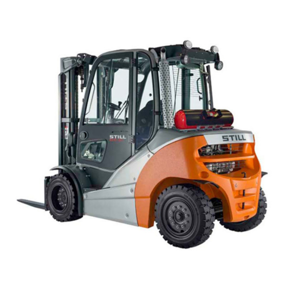
Page 14: Your Truck
Your truck Your truck Description of the truck General The trucks in the RX70-40/45/50 series with a load capacity of up to 5 t are equipped with an internal combustion engine/electric drive. This drive combines the advantages of the internal combustion engine with the precise control of an electric drive. - Page 15 Foreword Your truck Hydraulic system The required oil volume flow is provided via an adjustable hydraulic pump, which is linked to the internal combustion engine. The propor- tional valve technology provides particularly sensitive movements and safe handling of the load. The hydraulic functions can be parame- terised individually by the authorised service centre.
-
Page 16: General
Foreword Your truck In dual-pedal operation, the truck has one pedal for the "Forwards" drive direction and one pedal for the "Reverse" drive direction. Acceleration and braking behaviour can be individually selected from five different drive programmes. General The truck described in these operating instruc- tions corresponds to the applicable standards and safety regulations. -
Page 17: Conformity Marking
Foreword Your truck Conformity marking The manufacturer uses the conformity mark- ing to document the conformity of the industri- al truck with the relevant directives at the time of placing on the market: CE: in the European Union (EU) ●... -
Page 18: Declaration That Reflects The Content Of The Declaration Of Conformity
Your truck Declaration that reflects the content of the declaration of conformity Declaration STILL GmbH Berzeliusstraße 10 22113 Hamburg Germany We declare that the specified machine conforms to the most recent valid version of the directives specified below: ... -
Page 19: Accessories Overview
Foreword Your truck Accessories overview Key for key switch (2 pieces) ● Key for cab (variant) ● Hexagon socket wrench for emergency low- ● ering 57348011825 EN - 07/2023 - 14 7... -
Page 20: Labelling Points Overview
Foreword Your truck Labelling points overview Decal information: Fixing point for lifting gear Decal information: Caution / Read the oper- Manufacturer's label text ating instructions / Fasten seat belt / Apply Warning sign: Danger due to shearing/Dan- parking brake when leaving the truck / Pas- ger due to high fluid pressure sengers are not allowed / Do not jump off if Warning sign: Do not stand underneath the... -
Page 21: Nameplate
Foreword Your truck Nameplate The truck can be identified from the informa- tion on the nameplate. The information for the battery weights (5, 6) Type-Modèle-Typ / Serial no.-No. de série-Serien-Nr. / year-année-Baujahr and the ballast weight (7) only applies to elec- tric forklift trucks. -
Page 22: Stvzo (Road Traffic Licensing Regulations) Information
Foreword Your truck StVZO (Road Traffic Licensing Regulations) information This label includes information on the weight and load distribution of the truck. 7094_003-098_V2 Tare weight (in kg) Permitted total weight (in kg) Permitted front axle weight (in kg) Permitted rear axle weight (in kg) Payload (in kg) 10 57348011825 EN - 07/2023 - ... -
Page 23: Using The Truck
Foreword Using the truck Using the truck Intended use The truck described in these operating instruc- tions is suitable for lifting, transporting and stacking loads. The truck may only deployed for its intended use as set out and described in these operat- ing instructions. -
Page 24: Place Of Use
Foreword Using the truck Use for purposes other than those described in these operating instructions is prohibited. DANGER There is a risk of fatal injury from falling off the truck while it is moving! – It is prohibited to carry passengers on the truck. -
Page 25: Using Working Platforms
Foreword Using the truck The operating company must ensure suitable fire protection for the relevant application in the truck's surroundings. Depending on the application, additional fire protection must be provided on the truck. If in doubt, contact the relevant authorities. NOTE Please observe the definition of the following responsible person: "operating company". -
Page 26: Information About The Documentation
Foreword Information about the documentation Information about the documentation Documentation scope Original operating instructions ● Original operating instructions for attach- ● ments (variant) Spare parts list ● Depending on the truck equipment, "UPA" ● operating instructions may also be provided NOTE Refer to the additional information in the sec- tion entitled "Rules for the operating company... -
Page 27: Supplementary Documentation
Foreword Information about the documentation The operating company must ensure that all users have received, read and understood these operating instructions. Safely store the complete documentation and pass on to the subsequent operating company when transferring or selling the truck. NOTE Please observe the definition of the follow- ing responsible persons: "operating company"... -
Page 28: Issue Date And Topicality Of The Operating Instructions
The issue date and the version of these op- erating instructions can be found on the title page. STILL is constantly engaged in the further de- velopment of trucks. These operating instruc- tions are subject to change, and any claims based on the information and/or illustrations contained in them cannot be asserted. -
Page 29: Explanation Of Signal Terms Used
Foreword Information about the documentation Explanation of signal terms used DANGER Indicates procedures that must be strictly adhered to in order to prevent the risk of fatalities. WARNING Indicates procedures that must be strictly adhered to in order to prevent the risk of injuries. CAUTION Indicates procedures that must be strictly adhered to in order to prevent material damage and/or destruc-... - Page 30 Foreword Information about the documentation Abbrevi- Meaning Explanation ation Confirms conformity with product-specific Communauté Européenne European directives (CE labelling) Commission on the Rules for the Approval International commission on the rules for of the Electrical Equipment the approval of electrical equipment Direct Current Direct current DFÜ...
-
Page 31: Definition Of Directions
Foreword Information about the documentation Abbrevi- Meaning Explanation ation Tyres for simplified assembly, without Snap-In Tyre loose rim parts German regulations for approval of vehi- StVZO Straßenverkehrs-Zulassungs-Ordnung cles on public roads Ordinance on hazardous materials appli- TRGS Technische Regel für Gefahrstoffe cable in the Federal Republic of Germany Confirms conformity with the product-spe- UKCA... -
Page 32: Schematic Views
Foreword Information about the documentation Schematic views View of functions and operations This documentation explains the (usually se- quential) chain of certain functions or oper- ations. Schematic diagrams of a counterbal- ance truck are used to illustrate these proce- dures. -
Page 33: Environmental Considerations
Foreword Environmental considerations Environmental considerations Packaging During delivery of the truck, certain parts are packaged to provide protection during trans- port. This packaging must be removed com- pletely prior to initial start-up. ENVIRONMENT NOTE The packaging material must be disposed of properly after delivery of the truck. - Page 34 Foreword Environmental considerations 22 57348011825 EN - 07/2023 - 14...
-
Page 35: Safety
Safety... -
Page 36: Definition Of Terms Used For Responsible Persons
Safety Definition of terms used for responsible persons Definition of terms used for responsible persons Operating company The operating company is the natural or legal person or group who operates the truck or on whose authority the truck is used. The operating company must ensure that the truck is only used for its proper purpose and in compliance with the safety regulations set out... -
Page 37: Drivers
Safety Definition of terms used for responsible persons Drivers This truck may only be driven by suitable per- sons who are at least 18 years of age, have been trained in driving, have demonstrated their skills in driving and handling loads to the operating company or an authorised represen- tative, and have been specifically instructed to drive the truck. - Page 38 Safety Definition of terms used for responsible persons Prohibition of use by unauthorised per- sons The driver is responsible for the truck during working hours. He must not allow unauthor- ised persons to operate the truck. When leaving the truck, the driver must secure it against unauthorised use, e.g.
-
Page 39: Basic Principles For Safe Operation
Safety Basic principles for safe operation Basic principles for safe operation Insurance cover on company premises In many cases, company premises are restric- ted public traffic areas. NOTE The business liability insurance should be re- viewed to ensure that, in the event of any damage caused in restricted public traffic areas, there is insurance cover for the truck in respect of third parties. -
Page 40: Changes To The Overhead Guard And Roof Loads
Safety Basic principles for safe operation – Contact the authorised service centre be- fore converting or retrofitting the truck. The operating company is only permitted to make modifications to the truck independently if the manufacturer goes into liquidation and the company is not taken over by another le- gal person. -
Page 41: Warning About Any Manipulation Of The Internal Combustion Engine
STILL. CAUTION Installation and/or use of such products may there- fore have a negative impact on the design features of the truck and thus impair active and/or passive driving safety. -
Page 42: Damage, Defects And Misuse Of Safety Systems
Safety Basic principles for safe operation Damage, defects and misuse of safety systems Damage or other defects on the truck or at- tachment must be reported to the supervisor or responsible fleet manager immediately so that they can have the defect rectified. Trucks and attachments that are not functional or safe to drive may not be used until they have been properly repaired. -
Page 43: Tyres
Safety Basic principles for safe operation Tyres DANGER Risk to stability! Failure to observe the following information and in- structions can lead to a loss of stability. The truck may tip over, risk of accident! The following factors can lead to a loss of stability and are therefore prohibited: Different tyres on the same axle, e.g. -
Page 44: Medical Equipment
Safety Basic principles for safe operation Medical equipment WARNING Electromagnetic interference may occur on medical devices! Only use equipment that is sufficiently protected against electromagnetic interference. Medical equipment, such as pacemakers or hearing aids, may not work properly when the truck is in operation. - Page 45 Safety Basic principles for safe operation Length of the fork arms DANGER Risk of accident due to the incorrect selection of fork arms! – The fork arms must match the depth of the load. If the fork arms are too short, the load may fall off the arms after it has been picked up.
-
Page 46: Residual Risk
Safety Residual risk Residual risk Residual dangers, residual risks Despite working with care and complying with the standards and regulations, the possibility of other dangers arising when using the truck cannot be ruled out. The truck and all other system components comply with current safety requirements. -
Page 47: Special Risks Associated With Using The Truck And Attachments
Safety Residual risk ments, this can lead to an accident. In this case, the manufacturer is exempt from liability. Stability The stability of the truck has been tested to the latest technological standards. If the truck is used in the proper manner and in accord- ance with its intended use, the stability of the truck is guaranteed. - Page 48 Safety Residual risk use the truck correctly and without the risk of accidents. 36 57348011825 EN - 07/2023 - 14...
- Page 49 Safety Residual risk 57348011825 EN - 07/2023 - 14 37...
-
Page 50: Overview Of Hazards And Countermeasures
Safety Residual risk Overview of hazards and countermeasures NOTE This table is intended to help evaluate the hazards in your facility and applies to all drive types. It does not claim to be complete. – Observe the national regulations for the country in which the truck is being used. - Page 51 Safety Residual risk Hazard Course of action Check note Notes √ done - Not applicable Impermissible usage Provide operating in- German Ordinance on (improper usage) structions Industrial Safety and Health (BetrSichV) and German Health and labour protection law (ArbSchG) Written notice of in- German Ordinance on struction to driver Industrial Safety and...
-
Page 52: Danger To Employees
Safety Residual risk Hazard Course of action Check note Notes √ done - Not applicable DGUV rule 113-001 and observe the oper- ating instructions When operating driverless transport systems Roadway quality inad- Clean/clear roadways German Ordinance on equate Industrial Safety and Health (BetrSichV) Loading equipment in- Reposition load on pal-... - Page 53 Safety Residual risk The design and equipment of the truck comply with the standards and directives required for CE conformity. The design and equipment al- so comply with the standards and directives necessary for the UKCA compliance that is required in the United Kingdom. The design and equipment are therefore not part of the required scope of the hazard assessment.
-
Page 54: Safety Tests
Safety Safety tests Safety tests Regular safety inspection of the truck Safety inspection based on time and ex- traordinary incidents The operating company must ensure that the truck is checked by a specialist at least once a year or after particular incidents. As part of this inspection, a complete check of the technical condition of the truck must be performed with regard to accident safe-... -
Page 55: Trucks With Particle Filters
Safety Safety tests NOTE Observe the national regulations for the coun- try in which the truck is being used. Trucks with particle filters Trucks with particle filters (variant) may be op- erated in entirely or partially enclosed working areas. DANGER Risk to health from exhaust gases! Exhaust gases from internal combustion engines are harmful to your health. -
Page 56: Insulation Testing
Safety Safety tests used for responsible persons") and must be recorded in writing. NOTE Observe the TRGS 554 regulations and the national regulations of the country in which the truck is being used. Insulation testing The truck insulation must have sufficient insu- lation resistance. -
Page 57: Safety Regulations For Handling Consumables
Safety Safety regulations for handling consumables Safety regulations for handling consumables Permissible consumables WARNING Consumables can be dangerous! – Observe general information and safety informa- tion regarding the use of consumables. – Refer to the chapter entitled "Safety regula- tions for handling consumables". –... -
Page 58: Hydraulic Fluid
Safety Safety regulations for handling consumables WARNING Prolonged intensive contact with the skin can result in dryness and irritate the skin! – Avoid contact and consumption. – Wear protective gloves. – After any contact, wash the skin with soap and water, and then apply a skin care product. -
Page 59: Battery Acid
Safety Safety regulations for handling consumables WARNING These fluids are pressurised during op- eration of the truck and are hazardous to your health. – Do not allow the fluids to come into contact with the skin. – Avoid inhaling spray. –... -
Page 60: Diesel Fuel
Safety Safety regulations for handling consumables WARNING Battery acid contains dissolved sulphuric acid. This is corrosive. – When working with battery acid, use appropriate PSA (rubber gloves, apron, protection goggles). – When working with battery acid, nev- er wear a watch or jewellery. –... - Page 61 Safety Safety regulations for handling consumables WARNING Prolonged intensive contact with the skin can result in loss of skin oils and can irritate the skin! – Avoid contact and swallowing. – Wear protective gloves. – After any contact, wash the skin with soap and water, and then apply a skin care product.
-
Page 62: Coolant And Cooling Fluid
Safety Safety regulations for handling consumables Coolant and cooling fluid WARNING Coolant and cooling fluid can be hazard- ous to your health and the environment! Coolants are chemical corrosion inhib- itors and cooling system protecting agents such as Glysantin. The cooling fluid is an appropriate mixture of water and coolant. - Page 63 Safety Safety regulations for handling consumables – Always observe national regulations con- cerning the disposal of used oil. 57348011825 EN - 07/2023 - 14 51...
-
Page 64: Emissions
< 0.59 m/s the body (feet or seat sur- face) is subjected Truck model Uncertainty K 0.177 m/s RX70-40 106 dB RX70-45 106 dB Tests have indicated that the amplitude of the RX70-50 106 dB hand and arm vibrations on the steering wheel RX70-50/600 106 dB... - Page 65 Safety Emissions Exhaust gases Diesel engine emissions are harmful to your health. The particles contained in the exhaust CAUTION gases in particular are classified as carcino- genic. Risk to health from exhaust gases! Exhaust gases from internal combustion engines are harmful to your health.
- Page 66 Safety Emissions 54 57348011825 EN - 07/2023 - 14...
-
Page 67: Overviews
Overviews... -
Page 68: Truck Overview
Overviews Truck overview Truck overview 7331_003-001 Lift mast Fuel tank locking cap Overhead guard Bonnet Driver's compartment Drive axle Towing device Fork arms Steering axle Fork carriage 56 57348011825 EN - 07/2023 - 14... -
Page 69: Overview Of Driver's Compartment
Overviews Overview of driver's compartment Overview of driver's compartment Parking brake lever Bottle holder for max. 1.5 l bottles Steering wheel Driver's seat Key switch Compartment Display and operating unit Filler cap for windscreen washer reservoir Compartment for the operating instructions Accelerator pedal Operating devices for hydraulic and drive Brake pedal... -
Page 70: Operating Devices And Display Elements
Overviews Operating devices and display elements Operating devices and display elements Display and operating unit Hazard warning system button Operating hours display Front windscreen wiper button Time display (digital) Working spotlight button Particle filter display Drive programme selector button Rotating beacon display Softkey Lighting Interior lighting display Lighting symbol... -
Page 71: Operating Devices For Hydraulic And Driving Functions
Overviews Operating devices and display elements – If you have any questions, please contact your authorised service centre. Operating devices for hydraulic and driving functions Different versions of the operating devices are available for operating the truck's hydraulic functions and drive functions. The truck can be equipped with the following operating devices: Double mini-lever... -
Page 72: Double Mini-Lever
Overviews Operating devices and display elements Double mini-lever 6341_003-050 Drive direction switch "F1" function key "Attachments" cross lever "Lift mast" 360° lever Function key for the "5th Function" Display field for the hydraulic functions Signal horn button NOTE The drive direction switch (1) is inopera- ●... -
Page 73: Triple Mini-Lever
Overviews Operating devices and display elements Triple mini-lever 6341_003-051 Drive direction switch Signal horn button "Auxiliary hydraulics 1" operating lever "F1" function key "Auxiliary hydraulics 2" operating lever "Lift mast" 360° lever Function key for the "5th Function" Display field for the hydraulic functions NOTE The drive direction switch (1) is inopera- ●... -
Page 74: Quadruple Mini-Lever
Overviews Operating devices and display elements Quadruple mini-lever 6341_003-052 Drive direction switch Signal horn button "Tilt" operating lever "F1" function key "Auxiliary hydraulics 1" operating lever "Lift/lower" operating lever "Auxiliary hydraulics 2" operating lever Display field for the hydraulic functions Function key for the "5th Function" NOTE The drive direction switch (1) is inopera- ●... -
Page 75: Joystick 4Plus
Overviews Operating devices and display elements Joystick 4Plus 6210_003-087 Horizontal rocker button for the "3rd hydraul- LED for the clamp locking mechanism (var- ic function", tilting the lift mast iant) Symbols for the basic hydraulic functions Slider for the "4th hydraulic function", e.g. Pictograms for the 5th hydraulic function and side shift frame forwards/backward for the clamp locking mechanism (variant) -
Page 76: Fingertip
Overviews Operating devices and display elements Fingertip 6341_003-050 Signal horn button Drive direction switch LED for the "5th Function" "Lift/lower" operating lever Function key for the "5th Function" "Tilt" operating lever LED for the "Clamp release" "F1" function key Operating lever for "Auxiliary hydraulics 1" LED for "F1"... -
Page 77: Travel Direction Selector And Indicator Module (Variant)
Overviews Operating devices and display elements Travel direction selector and in- dicator module (variant) The travel direction selector and indicator module is located on the steering column be- low the steering wheel. NOTE If the drive direction switch on the operating device is defective and the truck stops in a danger area, the drive direction selection lever on the travel direction selector and indicator... - Page 78 Overviews Operating devices and display elements 66 57348011825 EN - 07/2023 - 14...
-
Page 79: Operation
Operation... -
Page 80: Checks And Tasks Before Daily Use
Operation Checks and tasks before daily use Checks and tasks before daily use Visual inspections and function checking WARNING Risk of injury from falling off the truck! When climbing onto the truck, there is a risk of getting stuck or slipping and falling. - Page 81 Operation Checks and tasks before daily use Component Course of action Ensure that the attachments are mounted correctly in accordance with the operating instructions from the manufacturer. Attachments (variant) Perform a visual inspection to ensure that the at- tachments are intact and are leak-tight. Perform checks to ensure that the attachments are working correctly.
- Page 82 Operation Checks and tasks before daily use Component Course of action To activate all available hydraulic functions once, actuate all hydraulic operating devices once. As a general rule: If hydraulic valves have not been operated for a long time, their function may be impaired. This ap- Working hydraulics plies regardless of the type and design of the hy- draulic valves.
-
Page 83: Climbing Into And Out Of The Truck
Operation Checks and tasks before daily use Climbing into and out of the truck WARNING Risk of injury when climbing into and out of the truck due to slipping, striking parts of the truck or becom- ing stuck! If the footwell cover is very dirty or smeared with oil, there is a risk of slipping. -
Page 84: Climbing Into And Out Of A Truck With A Raised Driver's Cab
Operation Checks and tasks before daily use To assist with climbing into and out of the truck, the footwell must be used as a step (5) and the handle (1) must be used for support. The post of the overhead guard (2) can also be used for support. - Page 85 Operation Checks and tasks before daily use CAUTION Components may become damaged through incor- rect use! Truck components, such as the driver's seat, steer- ing wheel, parking brake lever etc., are not designed to be used for climbing in and out of the truck and may be damaged due to misuse.
-
Page 86: Checking The Side Cover Is Locked
Operation Checks and tasks before daily use – Grip the handle (4) with your right hand and do not let go. – Place your right foot on the bottom step (5). – Place your left foot on the ground and climb down from the truck. -
Page 87: Adjusting The Msg 65/Msg 75 Driver's Seat
Operation Checks and tasks before daily use Adjusting the MSG 65/MSG 75 driver's seat DANGER There is a risk of accident if the seat or seat back- rest shifts suddenly, which could cause the driver to move in an uncontrolled manner. This may result in unintentional actuation of the steering or operating devices and thus cause the truck or load to move in an uncontrolled fashion. - Page 88 Operation Checks and tasks before daily use Moving the driver's seat – Raise the lever (1) and hold it in position. – Push the driver's seat into the desired posi- tion. – Release the lever. – Ensure that the driver's seat is securely en- gaged.
- Page 89 Operation Checks and tasks before daily use Adjusting the seat suspension NOTE The driver's seat can be adjusted to suit the weight of the individual driver. To obtain opti- mal settings for the seat suspension, the driv- er must perform the adjustment whilst sitting on the seat.
- Page 90 Operation Checks and tasks before daily use Adjusting the longitudinal horizontal suspension If necessary, the longitudinal horizontal sus- pension can be blocked using the locking lev- er (5) on the left-hand side of the driver's seat. Longitudinal horizontal suspension acti- vated Longitudinal horizontal suspension blocked...
- Page 91 Operation Checks and tasks before daily use Adjusting the backrest extension (var- iant) – Adjust the backrest extension (7) by pulling it out or pushing it into the desired position. To remove the backrest extension, move it past the end stop by firmly pushing it upwards. 6321_003-040_V3 Switching the seat heater (variant) on or ...
-
Page 92: Adjusting The Armrest
Operation Checks and tasks before daily use Adjusting the armrest DANGER There is a risk of accident if the armrest lowers suddenly, causing the driver to move in an uncon- trolled manner. This can result in unintentional ac- tuation of the steering or the operating devices and thus cause uncontrolled movements of the truck or load. -
Page 93: Adjusting The Steering Column
Operation Checks and tasks before daily use Adjusting the steering column DANGER Risk of accidents! Adjusting the steering column during travel may cause the truck to career out of control. – Adjust the steering column only when the truck is at a standstill. -
Page 94: Access Authorisation With Pin Code (Variant)
Operation Checks and tasks before daily use – Pull the emergency off switch (1) until it un- latches. 7312_003-183 Access authorisation with PIN code (variant) Description Trucks equipped with the "Access authorisa- tion with PIN code" variant are protected against unauthorised use by a five-digit driver PIN. - Page 95 PIN is only known to per- sons with corresponding access authorisation. The driver PINs are stored in the truck con- trol unit. These are still available if the display and operating unit has been changed. The au- thorised service centre can use a diagnostic device to read out the driver PIN and, if neces- sary, restore the factory default driver PIN.
- Page 96 Operation Checks and tasks before daily use ACCESS CODE input menu The driver enters the five-digit driver PIN (00000 to 99999) in this input menu. The driver PIN is entered using the buttons or Softkeys (1). The digits entered for the driver PIN (2) are not visible but are represented by circles instead.
- Page 97 Operation Checks and tasks before daily use After three invalid entry attempts, the mes- sage appears. The input is CODE DENIED then locked for five minutes before another attempt can be made. BQ_024_en_V2 Defining the driver PIN NOTE The driver PINs can be defined only by per- sons with the appropriate access authorisa- tion, e.g.
- Page 98 Operation Checks and tasks before daily use appears in the display. PASSWORD – Enter the four-digit password (factory de- fault: 2777) using the buttons (1). – Confirm the input using Softkey (2). BQ_030_en_V2 appears in the display. CONFIGURATION –...
- Page 99 Operation Checks and tasks before daily use Selecting the driver PIN In the menu, there are fifty ACCESS CODE possible driver PINs to choose from. The digit sequences can be set or changed in the submenu. NEW CODE Once the menu has been ac- ACCESS CODE cessed, the ...
- Page 100 Operation Checks and tasks before daily use appears in the display. CONFIRM submenu is used to confirm CONFIRM the new driver PIN. – Enter the new driver PIN for a second time in the field (8) using the buttons CONFIRM or Softkeys (7).
- Page 101 Operation Checks and tasks before daily use After three incorrect entries, the CODE message appears. NIED The display switches back to the ACCESS menu. The desired driver PIN must be CODE re-defined. BQ_024_en_V2 Changing the password It is recommended that you change the factory default password.
- Page 102 Operation Checks and tasks before daily use appears in the display. PASSWORD – Enter the current password using the but- tons (1). – Confirm the input using Softkey (2). BQ_030_en_V2 appears in the display. CONFIGURATION – Use the drive program selection button (1) and the menu change button (3) to select menu.
- Page 103 Operation Checks and tasks before daily use appears in PASSWORD/PASSWORD LEVEL the display. – Use the drive program selection button (1) and the menu change button (4) to select the desired (2). PASSWORD LEVEL – Confirm your selection using Soft- key ...
-
Page 104: Operating The Signal Horn
Operation Checks and tasks before daily use Operating the signal horn NOTE The signal horn is used to warn people against imminent danger or to announce an overtaking manoeuvre. – Push the signal horn button (1). The signal horn sounds. 7331_500-002 Seat belt DANGER... - Page 105 Operation Checks and tasks before daily use DANGER Only bracket doors (variant), the restraining bracket (variant) or the driver's cab (variant) with closed, fixed doors constitute a driver restraint system. Plastic doors (weather protection) do not constitute a restraint system! If the doors are open or have been removed, you must use an alternative suitable restraint system (e.g.
- Page 106 Operation Checks and tasks before daily use Fastening on a steep slope The automatic blocking mechanism prevents the belt from being extended whenever the truck is on a steep gradient. It is no longer possible to pull the seat belt out of the belt retractor.
-
Page 107: Using The Driver's Cab
Operation Checks and tasks before daily use CAUTION The seat belt may be damaged by heat! Do not subject the buckle or belt retractor to exces- sive heat when thawing. – Do not use air warmer than 60°C when thawing. Using the driver's cab ... - Page 108 Operation Checks and tasks before daily use Checking the service brake – Release the parking brake. – Depress the brake pedal (1). There must be a slight pedal clearance and then a noticeable pressure point at the brake. – Accelerate the unladen truck in a clear area.
- Page 109 Operation Checks and tasks before daily use WARNING There is no electrical braking assistance when the key switch is switched off! Switching off the key switch will de-energise the en- tire electrical system. The regenerative brake will not be available. CAUTION There is no power steering when the key switch is switched off!
-
Page 110: Checking The Steering System For Correct Function
Operation Checks and tasks before daily use Checking the regenerative brake DANGER Risk of accident due to reduced braking power! The regenerative brake may not be sufficient for emergency braking. – Always actuate the brake pedal (1) for emergency braking. -
Page 111: Zero Adjustment Of The Load Measurement (Variant)
Operation Checks and tasks before daily use WARNING No electric braking assistance is available when the emergency off switch is actuated! Actuating the emergency off switch will de-energise the entire electrical system. – To brake, actuate the service brake. – Slowly drive the truck forwards. –... - Page 112 Operation Checks and tasks before daily use NOTE Accurate zero adjustment is only possible if the fork is not carrying a load. Do not take up a load yet NOTE Accurate zero adjustment is only possible within the first lifting stage of the lift mast. When carrying out the zero adjustment, do not raise the fork more than 800 mm above the ground.
-
Page 113: Checking The Vertical Lift Mast Position (Variant) For Correct Function
Operation Checks and tasks before daily use Checking the vertical lift mast position (variant) for correct function NOTE The function check of the lift mast vertical po- sition (variant) must be carried out every time a truck is commissioned. –... -
Page 114: Operating The Display-Operating Unit
Operation Operating the display-operating unit Operating the display-operating unit Displays Standard display elements In the factory setting, the following indicators can be seen in the display and operating unit: Fuel level Shows the fuel level in the fuel tank in %. Drive programme Displays the current drive programme numerically (1-5). -
Page 115: Adjusting The Displays
Operation Operating the display-operating unit Adjusting the displays NOTE The parking brake must always be engaged when you adjust the displays. The displays cannot be adjusted if the parking brake is not engaged. NOTE When adjusting the displays, do not actuate the hydraulic system operating devices. -
Page 116: Symbols In The Display
Operation Operating the display-operating unit The display changes to the menu. PASSWORD NOTE It may be necessary to enter a password in order to configure the displays. This depends on the configuration of the display-operating unit. For configuration of the display-operating ●... - Page 117 Operation Operating the display-operating unit Symbols for operating messages Description Symbol Empty field No display Please wait Service required Lift limitation Reference cycle Battery charging Drive program Hour meter Odometer Daily hour meter Daily odometer Speed Steering angle Load Time Hydraulic system Exh.gas purifier Coolant temperature...
- Page 118 Operation Operating the display-operating unit Symbols for error messages Description Symbol Brake system malfunction Overheating of the engine Overheating Malfunction in the electrical system General malfunction Symbols for softkey functions of auxili- ary equipment The following symbols for softkey functions are used on the left of the display for auxiliary equipment: Description...
- Page 119 Operation Operating the display-operating unit Description Symbol Automatic mast vertical positioning ON Load measurement zero adjustment OFF Load measurement zero adjustment ON Load measurement OFF Load measurement ON Symbols for softkey functions for menu navigation and for acknowledging mes- sages The following symbols for the softkey func- tions are used on the left of the display for menu navigation and to acknowledge messag-...
- Page 120 Operation Operating the display-operating unit Screen for entering the fleet manager pass- word: BQ_037 Screen for entering the driver PIN (access code): BQ_038 108 57348011825 EN - 07/2023 - 14...
-
Page 121: Setting The Date Or Time
Operation Operating the display-operating unit Setting the date or time – Switch to the menu; see CONFIGURATION the chapter entitled "Adjusting the displays". – Press the Drive programme button (1) or the Menu change button (2) repeatedly until option appears. TIME –... -
Page 122: Setting The Language
Operation Operating the display-operating unit NOTE The daily operating hours are reset in the same manner. Setting the language 1 2 3 4 The displays can be shown in additional lan- guages: – Switch to the menu; see CONFIGURATION the chapter entitled "Adjusting the displays". -
Page 123: Configuring Blue-Q Efficiency Mode
Operation Operating the display-operating unit Changing the Softkey functions: A grey bar (3) highlights the Softkey column. This is the right-hand column in the example shown here. These additional functions can now be switched on and off via the corre- sponding Softkeys (2). -
Page 124: Shock Recognition (Variant)
Operation Operating the display-operating unit FIXED-FLEX Blue-Q is turned on whenever the truck is ● commissioned. The driver can use the Blue- Q button to switch efficiency mode on and off at any time while the truck is being oper- ated –... -
Page 125: Switching On And Starting
Operation Switching on and starting Switching on and starting Switching on the key switch WARNING Before switching on the key switch, all tests prior to start-up must be performed without detecting any defects. – Perform the tests prior to commissioning. –... - Page 126 Operation Switching on and starting When the key switch is switched on, the dis- play shows the welcome screen in the set lan- guage until the truck controls have completely started up. If the truck has the "access authorisation with PIN code"...
-
Page 127: Starting The Engine
Operation Switching on and starting NOTE Additional information may appear on the dis- play. Refer to the information in the chapter enti- ● tled "Display messages". Starting the engine DANGER Risk to health from exhaust gases! Exhaust gases from internal combustion engines are harmful to your health. - Page 128 Operation Switching on and starting CAUTION Risk of engine damage! If the message appears on the OIL PRESSURE display after starting the motor, there may be insuffi- cient engine lubrication. Insufficient lubrication may cause engine damage. – Immediately switch off the engine. –...
-
Page 129: Lighting
Operation Lighting Lighting Switching the lighting on and off NOTE All of the lighting described below can be ret- rofitted by the authorised service centre. Drive lighting – To switch on the parking light, press the button (1). The front sidelights and the tail lights light up. -
Page 130: Switching The Working Spotlight For Reverse Travel On And Off
Operation Lighting Switching the working spotlight for reverse travel on and off The working spotlight for reverse travel is at- tached to the overhead guard at the rear. It provides optimal illumination of the roadway if the truck is travelling in reverse. –... -
Page 131: Switching The Hazard Warning System On And Off
Operation Lighting The turn indicators and the turn indicator dis- play (2) or (3) on the display-operating unit flash. – To switch off, push the turn indicator switch to the centre position. The turn indicators and the turn indicator dis- plays on the display-operating unit stop flash- ing. -
Page 132: Switching The Rotating Beacon On And Off
Operation Lighting Switching the rotating beacon on and off – Press the Softkey (1) to switch on the rotating beacon. The rotating beacon is switched on. The sym- bol is displayed. – To switch off the rotating beacon, press the Softkey ... - Page 133 Operation Lighting NOTE This function is not available if the truck is equipped with rear window heating. – Turn the key switch to position "I". – Press Softkey (1) to switch on the work- ing spotlights. The working spotlights are switched on. The symbol is displayed.
-
Page 134: Still Safetylight (Variant)
Danger of damage to eyes from looking into the STILL SafetyLight. Do not look into the STILL SafetyLight. The STILL SafetyLight is a visual warning unit designed to enable early detection of trucks in driving areas with low visibility (such as drive lanes, high racks), as well as at blind junctions. - Page 135 Depending on the configuration of the truck, the STILL SafetyLight automatically switches itself on when the truck is moving. The STILL SafetyLight can also be switched on and off on the display-operating unit. – To do so, press the corresponding button. NOTE If the truck is to be operated on public roads, the STILL SafetyLight must be switched off.
-
Page 136: Blue-Q Efficiency Mode
Operation Blue-Q efficiency mode Blue-Q efficiency mode Functional description The Blue-Q efficiency mode affects both the drive unit and the activation of the additional consumers, and reduces the truck's energy consumption. If the efficiency mode has been activated, the acceleration behaviour of the truck changes to make acceleration more moderate. -
Page 137: Switching Off Additional Consumers
Operation Blue-Q efficiency mode Switching off additional consumers If the Blue-Q efficiency mode is activated, the controller switches off various additional con- sumers after a few seconds in certain condi- tions. The additional consumers available de- pend on the truck equipment. The following ta- ble shows the conditions that cause additional consumers to be switched off. -
Page 138: Switching Efficiency Mode Blue-Q On And Off
Operation Blue-Q efficiency mode Switching efficiency mode Blue- Q on and off NOTE The Blue-Q efficiency mode can be switched on and off in the STANDARD and FIXED- FLEX operating modes. If the FIXED operat- ing mode is configured in the display-operat- ing unit, the Blue-Q button is disabled and the Blue-Q efficiency mode is switched on per- manently. -
Page 139: Driving
Operation Driving Driving Safety regulations when driving Driving conduct The driver must follow the public rules of the road when driving in company traffic. The speed must be appropriate to the local conditions. For example, the driver must drive slowly around corners, in tight passageways, when driving through swing-doors, at blind spots, or on uneven surfaces. - Page 140 There is a risk of accident! – Do not use devices during travel or when handling loads. – Set the volume so that warning signals can still be heard. WARNING In areas where use of mobile phones is prohibited, use of a mobile phone or radio telephone is not per- mitted.
-
Page 141: Roadways
For pallets, these are 7321_003-019 as follows: with pallet with pallet Aisle width (mm) 1000 x 1200 800 x 1200 crosswise lengthwise RX70-40 3912 4112 RX70-45 3942 4142 RX70-50 4037 4237 The truck may only be used on roadways that... - Page 142 The gradient values in no way represent the normal daily operating conditions. Max. gradient in % with load without load RX70-40 RX70-45 RX70-50 The ascending and descending gradients must not exceed the gradients listed above and must have a rough surface.
-
Page 143: Setting The Drive Programmes
Operation Driving height is based on the overall height of the lift mast and the dimensions of the load. Observe the technical data (see C hapter "Technical ⇒ data", Page 355 ). Rules for roadways and the working area It is only permitted to drive on routes author- ised for traffic by the operating company (see C hapter "Definition of terms used for respon- ⇒ ... -
Page 144: Actuating The Vertical Rocker Button For The "Drive Direction", Joystick 4Plus Version
Operation Driving Drive program Speed (km/h) Acceleration (%) (forwards/backwards) Deceleration (%) (forwards/backwards) Reversing (%) (forwards/backwards) Brake retardation (%) (electric brake booster) Actuating the vertical rocker but- ton for the "drive direction", Joy- stick 4Plus version – For the "forward" drive direction, push the vertical rocker button for the "drive direc- tion" (1) upwards (A). -
Page 145: Actuating The Drive Direction Switch With The Mini-Lever Version
Operation Driving Actuating the drive direction switch with the mini-lever ver- sion – For the "forwards" drive direction, push the drive direction switch (1) forwards. – For the "backward" drive direction, pull the drive direction switch (1) backward. NOTE If the drive direction switch (1) is defective and the truck stops in a danger area, the drive direction selection lever on the travel direction selector and indicator module (variant) can be... -
Page 146: Indicator Module Version
Operation Driving Actuating the drive direction se- lection lever with the travel direc- tion selector and indicator mod- ule version – For the "forwards" drive direction, push the drive direction selection lever (1) forwards. – For the "backwards" drive direction, push the drive direction selection lever (1) back- wards. - Page 147 Operation Driving – Release the parking brake. – Select the desired drive direction. The indicator for the selected drive direction ("forwards" (1) or "backwards" (2)) lights up on the display and operating unit. NOTE Depending on the equipment, an acoustic sig- nal (variant) may sound a warning during re- verse travel, the warning light (variant) may light up or the hazard warning system (variant)
-
Page 148: Starting Drive Mode, Dual Pedal Version (Variant)
If the truck still cannot be operat- ed, park the truck securely and contact your authorised service centre. - Page 149 Operation Driving – Actuate the right-hand accelerator pedal (1) to drive "forward" and actuate the left-hand accelerator pedal (2) to drive "backward". NOTE In the dual pedal version, the drive direction switches on the operating devices do not func- tion. 5060_003-085 The indicator for the selected drive direction ...
-
Page 150: Operating The Service Brake
If the truck still cannot be operat- ed, park the truck securely and contact your authorised service centre. - Page 151 Operation Driving DANGER Risk of accident! If the service brake fails, the truck cannot brake suffi- ciently. – Bring the truck to a standstill by applying the park- ing brake. – Do not operate the truck again until the service brake has been repaired.
-
Page 152: Actuating The Mechanical Parking Brake
Operation Driving Actuating the mechanical park- ing brake DANGER There is a risk of being run over if the truck rolls away, and therefore a danger to life. – The truck must not be parked on a slope. – In emergencies, secure with wedges on the side facing downhill. - Page 153 Operation Driving Releasing the parking brake – Pull the parking brake lever (1) down fully out of the middle position. – In the lower lever position, pull out the lever knob and then guide the parking brake lever up fully. NOTE The parking brake lever swivels to the up- per position automatically by means of spring...
-
Page 154: Steering
Operation Driving Steering DANGER If the hydraulics fail, there is a risk of accident as the steering characteristics have changed. – Do not operate the truck if it has a defective steer- ing system. – Steer the truck by turning the steering wheel (1) accordingly. -
Page 155: Driving On Ascending And Descending Gradients
Operation Driving Driving on ascending and de- scending gradients DANGER Danger to life! Driving on ascending and descending gradients car- ries special dangers! – Always follow the instructions below. – On ascending and descending gradients, the load must be carried facing uphill. –... -
Page 156: Reducing Speed With A Raised Load (Variant)
Operation Driving Reducing speed with a raised load (variant) This function (variant) reduces the speed of the truck with a raised load. 7321_003-052_en_V2 Automatic shut-off of the internal combustion engine (variant) The truck is equipped with an automatic shut- off function that shuts off the internal combus- tion engine when certain conditions apply si- multaneously after a preset waiting time has... -
Page 157: Parking
Operation Parking Parking Parking the truck securely and switching it off DANGER Risk of fatal injury from being run over if the truck rolls away! – The truck must not be parked on a slope. – In emergencies, secure the truck us- ing wedges on the side facing down- hill. -
Page 158: Wheel Chock (Variant)
Operation Parking Wheel chock (variant) The wheel chock (variant) is used to prevent the truck from rolling away on a slope. – Lift handle (2) on the support mounting. – Remove wheel chock (1) from the support mounting. – Push the wheel chock under a front axle wheel on the side facing the downhill slope. -
Page 159: Lifting
Operation Lifting Lifting Lifting system variants The movement of the fork carriage and the lift mast heavily depends on the following equip- ment: The lift mast with which the truck is equip- ● ped, see C hapter "Types of lift mast", ⇒ ... -
Page 160: Automatic Mast Vertical Positioning (Variant)
Operation Lifting Overriding and reactivating the auto- matic lift cut out If a load needs to be lifted to the truck's maxi- mum lift height and the automatic lift cut out function is not required, it is possible to over- ride the lift cut out. - Page 161 Operation Lifting CAUTION Risk of damage to property due to the lift mast collid- ing with racks or other objects! – Before using the "automatic mast vertical position- ing" comfort feature, position the truck at a suffi- cient distance from racks and other objects. The "automatic mast vertical positioning"...
- Page 162 Operation Lifting Automatic movement into the "automat- ic mast vertical position" – Press the Softkey (1). The "automatic mast vertical positioning" com- fort feature is switched on. The (2) sym- bol is displayed. – Tilt the lift mast forwards. The lift mast stops automatically as soon as the preselected setting for "automatic mast vertical positioning"...
- Page 163 Operation Lifting The lift mast is tilted forwards and stops as soon as the vertical position is reached. The arrow above the bar shown on the screen of the display and operating unit represents the "automatic mast vertical position". To tilt the lift mast forwards beyond the vertical position: –...
-
Page 164: Types Of Lift Mast
Operation Lifting Calibrating the "automatic mast vertical position" – Set the lift mast to the required position. – Press and hold down the Softkey (1) for at least five seconds. The message ? VERTICAL POSITION pears in the display. Storing the mast position: –... -
Page 165: Malfunctions During Lifting Mode
Operation Lifting Triplex lift mast (variant) During lifting, the inner lift cylinder moves up to free lift (3), and then the outer lift cylinders raise the inner lift mast up to the max. height (2). DANGER Risk of accident due to collision of the lift mast or load with low ceilings or entrances. -
Page 166: Hydraulic Blocking Function
Operation Lifting Load chains not under tension DANGER Danger caused by a falling load! – Make sure that the chain(s) does (do) not become slack when lowering the load. Slack chains can, for instance, result from: Resting the fork carriage or the load on the ●... -
Page 167: Lifting System Operating Devices
Operation Lifting Emergency lowering of the load after the hydraulics blocking function has been triggered If the truck's hydraulics are disabled by the exhaust valve of the hydraulic blocking func- tion, either permanently or due to a technical fault, it is possible to lower a raised load with emergency lowering at the valve block, see C hapter "Emergency lowering", Page 288 . -
Page 168: Controlling The Lifting System Using A Double Mini-Lever
Operation Lifting Controlling the lifting system us- ing a double mini-lever DANGER Reaching into or climbing between moving parts of the truck (e.g. lift mast, sideshifts, working equip- ment, load carrying devices etc.) can lead to seri- ous injury or death and is therefore prohibited. –... - Page 169 Operation Lifting Lifting/lowering the fork carriage To lift the fork carriage: – Move the "lift mast" 360° lever (3) in the direction of the arrow (B). To lower the fork carriage: – Move the "lift mast" 360° lever (3) in the direction of the arrow (A). Tilting the lift mast To tilt the lift mast forwards: –...
-
Page 170: Controlling The Lifting System Using A Triple Mini-Lever
Operation Lifting Controlling the lifting system us- ing a triple mini-lever DANGER Reaching into or climbing between moving parts of the truck (e.g. lift mast, sideshifts, working equip- ment, load carrying devices etc.) can lead to seri- ous injury or death and is therefore prohibited. –... - Page 171 Operation Lifting – Move the "lift mast" 360° lever (3) in the direction of the arrow (A). Tilting the lift mast To tilt the lift mast forwards: – Move the "lift mast" 360° lever (4) in the direction of the arrow (C). To tilt the lift mast backwards: –...
-
Page 172: Controlling The Lifting System Using A Quadruple Mini-Lever
Operation Lifting Controlling the lifting system us- ing a quadruple mini-lever DANGER Reaching into or climbing between moving parts of the truck (e.g. lift mast, sideshifts, working equip- ment, load carrying devices etc.) can lead to seri- ous injury or death and is therefore prohibited. –... -
Page 173: Controlling The Lifting System Using The Joystick 4Plus
Operation Lifting – Move the "lifting/lowering" operating lev- er (3) in the direction of the arrow (A). Tilting the lift mast To tilt the lift mast forwards: – Move the "lift mast" operating lever (4) in the direction of the arrow (C). To tilt the lift mast backwards: –... - Page 174 Operation Lifting Lifting/lowering the fork carriage To lift the fork carriage: – Pull the Joystick 4Plus (1) backwards (B). To lower the fork carriage: – Push the Joystick 4Plus (1) forwards (A). 6210_003-089 Tilting the lift mast To tilt the lift mast forwards: – Tilt the horizontal rocker button (2) to the left (C).
- Page 175 Operation Lifting Fork carriage sideshift To move the fork carriage to the left: – Push the Joystick 4Plus (1) to the left (E). To move the fork carriage to the right: – Push the Joystick 4Plus (1) to the right (F). NOTE The symbols on the Joystick 4Plus indicate the direction of movement of the lift mast or fork carriage.
- Page 176 Operation Lifting Controlling the lifting system us- ing the Fingertip DANGER Reaching into or climbing between moving parts of the truck (e.g. lift mast, sideshifts, working equip- ment, load carrying devices etc.) can lead to seri- ous injury or death and is therefore prohibited. –...
-
Page 177: Fork Wear Protection (Variant)
Operation Lifting Tilting the lift mast To tilt the lift mast forwards: – Move the "tilting" operating lever (1) in the direction of the arrow (C). To tilt the lift mast backwards: – Move the "tilting" operating lever (1) in the direction of the arrow (D). Movements of the lifting system and meanings of the pictograms Lowering... -
Page 178: Changing The Fork Arms
Operation Lifting Changing the fork arms DANGER Risk of fatal injury from being run over if the truck rolls away! – Do not park the truck on a gradient. – Apply the parking brake. – Change the fork arms in a separate, safe location on a level surface. - Page 179 Operation Lifting Removal – Select a pallet corresponding to the fork arm size. – Set down the pallet next to the fork carriage on the side chosen for removal. – Lift the fork carriage until the fork arms are approx. 3 cm above the pallet.
-
Page 180: Fork Extension (Variant)
Operation Lifting Fork extension (variant) DANGER There is a risk of fatal injury from being run over if the truck rolls away. – Do not park the truck on a slope. – Apply the parking brake. – Change the fork extension in a cordoned-off, safe location on a level surface. - Page 181 Operation Lifting Attaching DANGER Risk of fatal injury from falling load! At least 60% of the length of the fork extension must lie on the fork arm. No more than 40% of the length of the fork extension may overhang the end of the fork arm.
-
Page 182: Operation With Reversible Fork Arms (Variant)
Operation Lifting Operation with reversible fork arms (variant) DANGER Risk to life from falling load! Standard fork arms are not structurally designed for reverse operation. If this instruction is not observed, it can lead to material failure and the load falling. –... - Page 183 Operation Lifting Reversible fork arms (1) can be used to reach an additional lift height. The reversible fork arms are installed on the fork carriage in the same manner as standard fork arms. Loads may be lifted on and beneath the reversible fork arms.
-
Page 184: Handling Loads
Operation Handling loads Handling loads Safety regulations when handing loads The safety regulations for handling loads are shown in the following sections. DANGER There is a risk to life caused by falling loads or if parts of the truck are being lowered. –... - Page 185 Operation Handling loads DANGER Risk of fatal injury from the truck losing stability! Never exceed the load capacity indicated on the capacity rating plate. This applies to compact and homogeneous loads. If these values are exceeded, the stability and rigidity of the fork arms and lift mast cannot be guaranteed.
- Page 186 Operation Handling loads Basic capacity rating plate 6219_003-337 Basic capacity rating plate Permissible lift height Weight of load to be lifted Distance between the load centre of gravity and the fork back There is always at least one capacity rating plate on the truck: the basic capacity rating plate.
- Page 187 Operation Handling loads Example of reading the capacity rating plate: The position numbers in the adjacent graphic correspond to the position numbers on the ba- sic capacity rating plate. Distance between the load centre of 5880 mm gravity and the fork back: 600 mm Permissible lift height: 5880 mm Weight of load to be lifted: 1000 kg The distance between the load centre of grav-...
- Page 188 Operation Handling loads A large sideshift enables a strongly off-centre load position. A large centre offset of the load results in a large reduction in the load capacity of the truck. XZP150 100x40x1200 h(mm) Since non-integrated attachments can be re- placed, multiple residual load capacity rating 6580 plates for attachments on one truck are pos-...
-
Page 189: Load Measurement (Variant)
Operation Handling loads Load measurement (variant) Description Knowing the weight of the load to be trans- ported gives the driver greater security. If the truck is equipped with the "load measurement" (variant) comfort feature, the weight of the lif- ted load can be measured and shown in the display-operating unit. - Page 190 Operation Handling loads NOTE Accurate load measurement is only possible under the following conditions: The hydraulic oil is at normal operating tem- ● perature The load is at rest at the beginning of the ● load measurement The load corresponds to at least 10% of the ●...
-
Page 191: Picking Up Loads
Operation Handling loads NOTE During the following process, the fork carriage must be lowered slightly and then stopped abruptly. While doing so, the fork must not touch the ground, otherwise the load meas- urement will not be accurate. To stop the low- ering procedure quickly, release the operating device for lowering so that it jumps into the zero position. -
Page 192: Danger Area
Operation Handling loads Loads are to be picked up and transported as close to the middle as possible. DANGER Risk of accident from a falling load! When transporting small items, attach a load safety guard (variant) to prevent the load from falling on the driver. -
Page 193: Transporting Pallets
Operation Handling loads DANGER People may be injured in the danger area of the truck! The danger area of the truck must be completely clear of all personnel, except the driver in his normal operating position. If persons fail to leave the danger area despite warnings: –... -
Page 194: Transporting Suspended Loads
Operation Handling loads Transporting suspended loads Before transporting suspended loads, consult the national regulatory authorities (in Germa- ny, the employer's liability insurance associa- tions). National regulations may place restrictions on these operations, e.g. in Italy. Contact the rel- evant authorities. If there are no country-specific regulations for suspended loads in the country of use, the following instructions for safe handling must... -
Page 195: Load Pick Up
Operation Handling loads Take particular care to ensure that there is ● no one in the drive direction in the driving lane. If, despite this, the load begins to swing, ● ensure that no person is placed at risk. DANGER Risk of accident! When transporting suspended loads, never perform or end driving and load movements abruptly. - Page 196 Operation Handling loads – Approach the racking carefully, brake gently and stop just in front of the racking. 6210_800-005 – Position the forks. – Set lift mast to vertical. – Lift the fork carriage to the stacking height. CAUTION Component damage possible! When inserting the fork into the racking, ensure that...
- Page 197 Operation Handling loads – Insert the fork as far under the load as pos- sible. Stop the truck as soon as the fork back is resting on the load. The centre of gravity of the load must be positioned be- tween the fork arms in the middle.
- Page 198 Operation Handling loads – Lower the load while maintaining ground clearance. 5060_003-102 – Tilt the lift mast backwards. The load can be transported. 5060_003-101 186 57348011825 EN - 07/2023 - 14...
-
Page 199: Transporting Loads
Operation Handling loads Transporting loads NOTE Observe the information in the chapter entitled "Safety regulations when driving". DANGER The higher a load is lifted, the less stable it be- comes. The truck can tip over or the load can fall, increasing the risk of accident! Driving with a raised load and the lift mast tilted for- ward is not permitted. - Page 200 Operation Handling loads – Never drive with a load protruding to the side (e.g. with the sideshift)! 6210_800-014 Determining visibility conditions when driving with a load e3861567 Area that is not visible (max. 1085 mm) Load (varies depending on operator) Load height (in driving position) Driver's eye level 4000 mm (distance to the front from the rear...
-
Page 201: Setting Down Loads
Operation Handling loads Procedure: The driver moves into position in his seat. ● The area that is not visible (A) is deter- ● mined based on the load (Y) and the length of the route (D). If the area that is not visible exceeds ●... - Page 202 Operation Handling loads WARNING Risk of accident from a falling load! If the fork or the load remains suspended during low- ering, the load may fall. – When removing from stock, move the truck far enough back so that the load and the fork can be lowered freely.
-
Page 203: Driving On Lifts
Operation Handling loads Driving on lifts The driver may only use this truck on lifts with a sufficient rated capacity and for which the operating company has been granted authori- sation. DANGER There is a risk to life if you are crushed or run over by the truck. -
Page 204: Driving On Loading Bridges
Operation Handling loads Driving on loading bridges DANGER Risk of accident if the truck crashes! Steering movements can cause the tail end to veer off the loading bridge towards the edge. This may cause the truck to crash. The lorry driver and the truck driver must agree on the lorry's departure time. -
Page 205: Particle Filter System
Operation Particle filter system Particle filter system Particle filter - Function DANGER Risk to health from exhaust gases! Exhaust gases from internal combustion engines are harmful to your health. In particular, the soot particles con- tained in the diesel exhaust gas can cause cancer. Allowing the internal combustion engine to idle rep- resents a risk of poisoning from the CO, CH and components contained in the exhaust gas. - Page 206 Operation Particle filter system prevent a sufficiently high exhaust gas tem- perature being reached. This causes the re- generation process to be disrupted. The soot filtered out of the exhaust gas then collects in the particle filter, as it is not burned off during the continuous regeneration process.
-
Page 207: Particle Filter - Performing Parked Regeneration
Operation Particle filter system Particle filter - Performing parked regeneration CAUTION Risk of damage to components! If parked regenera- tion is not performed when required, the particle filter may become damaged. A full parked regeneration must be performed in or- der to completely empty the particle filter. - Page 208 Operation Particle filter system WARNING There is a risk of fire and burns during parked regen- eration due to very hot exhaust gases! During parked regeneration, high temperatures occur in the particle filter, in the exhaust system and in the surrounding area.
- Page 209 Operation Particle filter system – Switch the key switch (1) to position "0" and wait until the display has switched off. – Turn the key switch back to the "I" position. 7071_003-101 The message START PARK. REG.? well as the softkeys (1) and (2) ap- pear on the display.
- Page 210 Operation Particle filter system – Start the engine. To do this, turn the switch key (1) to position "II" and hold it there until the engine has started. Then release the switch key. 7071_003-101 The particle filter regeneration process is star- ...
-
Page 211: Particle Filter - Displays
Operation Particle filter system If the status bar disappears and REGENERA- appears on the display, TION COMPLETED the parked regeneration process is complete. The truck is ready for operation again. NOTE The system requests parked regeneration ev- ery 500 operating hours at the latest if it has not already been performed due to soot accumulation in the particle filter. - Page 212 Operation Particle filter system Until parked regeneration has been carried out, the maximum Parked regeneration of the par- PARK. REG. speed of the truck is reduced ticle filter is urgently required. URGENT! ! ! to 2 km/h. The lifting speed is restricted.
-
Page 213: Attachments
Fitting attachments If the truck is equipped with an integrated at- tachment (variant) at the factory, the specifica- tions in the STILL operating instructions for integrated attachments must be observed. If attachments are fitted at the place of use, the specifications in the operating instructions from the attachment manufacturer must be ob- served. - Page 214 Operation Attachments WARNING Risk of accident due to incorrect labelling! The use of attachments can cause accidents if the labelling is incorrect or missing. If there is not an at- tachment-specific residual load capacity rating plate on the truck and not all operating devices are marked with appropriate pictograms, incorrect operation is possible.
-
Page 215: Releasing The Pressure From The Hydraulic System
Operation Attachments Mounting attachments Mounting an attachment and connecting the energy supply for an attachment must only be performed by competent persons in ac- cordance with the information provided by the manufacturer and supplier of the attachment. After each installation, the attachment must be checked for correct function prior to initial commissioning. - Page 216 Operation Attachments Releasing the pressure NOTE In trucks with the "FleetManager" or "access authorisation with PIN code" equipment var- iants, access authorisation must be enabled. – Switch on the key switch. Do not start the engine. – Wait two to three seconds. –...
-
Page 217: General Instructions For Controlling Attachments
Operation Attachments General instructions for control- ling attachments The way in which attachments (variant) are controlled depends on the operating devices included in the truck's equipment. Essentially, a distinction is drawn between: Double mini-lever ● Double mini-lever and 5th function (var- ●... - Page 218 Operation Attachments NOTE Further variants and functions are available in addition to the functions described below. The directions of movement can be seen in the pictograms on the operating devices. NOTE All the attachments described fall into the cat- egory of equipment variants. Please see the respective operating instructions for an exact description of the respective movements/ac- tions of the attachment fitted.
-
Page 219: Controlling Attachments Using A Double Mini-Lever
Operation Attachments Controlling attachments using a double mini-lever In this version, the attachments (variant) are controlled using the "attachments" cross lev- er (1). The adhesive label bearing the picto- grams for the hydraulic functions (2) is affixed at the designated point. –... - Page 220 Operation Attachments NOTE The pictograms are affixed according to the attachment fitted at the factory. If an attach- ment with different functions is fitted, the au- thorised service centre must check that the pictograms bear the correct representation and must change them if necessary. Clamp locking mechanism ...
-
Page 221: Controlling Attachments Using The Double Mini-Lever And The 5Th Function
Operation Attachments Controlling attachments using the double mini-lever and the 5th function NOTE For technical reasons, clamping attachments must not be controlled via the "5th function". The function key for the "5th function" (3) and the cross lever (1) are used to control the "5th function". - Page 222 Operation Attachments Example using the pictograms for configura- tion (1): If the "attachments" cross lever (1) is moved in the direction of the arrow (A), the fork is extended. If the function key for the "5th function" (3) is actuated and the "attachments" cross lever (1) is moved in the direction of the arrow (A), the fork arms open.
-
Page 223: Controlling Attachments Using A Triple Mini-Lever
Operation Attachments Controlling attachments using a triple mini-lever In this version, the attachments (variant) are controlled using the operating levers (1, 2). The adhesive label bearing the pictograms for the hydraulic functions (3) for the operating lever (2) and the adhesive label (4) for the op- erating lever (1) are affixed at the designated points. - Page 224 Operation Attachments Picto- Attachment function gram Tip shovel over Tip shovel back NOTE The pictograms are affixed according to the attachment fitted at the factory. If an attach- ment with different functions is fitted, the au- thorised service centre must check that the pictograms bear the correct representation and must change them if necessary.
-
Page 225: Controlling Attachments Using The Triple Mini-Lever And The 5Th Function
Operation Attachments Controlling attachments using the triple mini-lever and the 5th function NOTE For technical reasons, clamping attachments must not be controlled via the "5th function". The function key for the "5th function" (2) and the operating lever (1) are used to control the "5th function". -
Page 226: Controlling Attachments Using A Quadruple Mini-Lever
Operation Attachments Example using the pictograms for configura- tion (1): If the operating lever (1) is moved in the direc- tion of the arrow (E), the sideshift moves to the left. If the function key for the "5th function" (2) is actuated and the operating lever (1) is moved in the direction of the arrow (E), the fork arms open. - Page 227 Operation Attachments The pictograms on the operating levers show the respective functions that are activated by these levers. The following applies: – Move the operating lever (1) in the direction of the arrow (A) or (B). The attachment moves accordingly in the di- rections (A) or (B) as shown in the pictogram.
- Page 228 Operation Attachments Clamp locking mechanism – To release the clamp locking mechanism, push the operating lever (2) forwards. The clamp locking mechanism is released. The LED for the "clamp release" (1) lights up and remains lit while the clamp locking mech- anism is released.
-
Page 229: Controlling Attachments Using The Quadruple Mini-Lever And The 5Th Function
Operation Attachments Controlling attachments using the quadruple mini-lever and the 5th function NOTE For technical reasons, clamping attachments must not be controlled via the "5th function". The function key for the "5th function" (2) and the operating lever (1) are used to control the "5th function". - Page 230 Operation Attachments Picto- Attachment function gram Adjust fork arms: close Rotate to the left Rotate to the right NOTE The pictograms are affixed according to the attachment fitted at the factory. If an attach- ment with different functions is fitted, the au- thorised service centre must check that the pictograms bear the correct representation and must change them if necessary.
-
Page 231: Controlling Attachments Using The Joystick 4Plus
Operation Attachments Controlling attachments using the Joystick 4Plus In this version, the attachments (variant) are controlled via the Joystick 4Plus (1) and the slider (4). The adhesive label bearing the pic- tograms for the hydraulic functions (2) for the Joystick 4Plus (1) and the adhesive label (3) for the slider (4) are affixed at the designated points. - Page 232 Operation Attachments Picto- Attachment function gram Rotate to the left Rotate to the right Tip shovel over Tip shovel back NOTE The pictograms are affixed according to the attachment fitted at the factory. If an attach- ment with different functions is fitted, the au- thorised service centre must check that the pictograms bear the correct representation and must change them if necessary.
-
Page 233: Controlling Attachments Using The Joystick 4Plus And The 5Th Function
Operation Attachments Controlling attachments using the Joystick 4Plus and the 5th function NOTE For technical reasons, clamping attachments must not be controlled via the 5th function. Use shift key "F" (4) and the Joystick 4Plus (2) and the horizontal rocker button (1) to control the "5th function". The adhesive label bearing the pictograms for the hydraulic functions (3) for the Joy- stick 4Plus (2) and for the horizontal rocker 6219_003-166_V2... -
Page 234: Controlling Attachments Using The Fingertip
Operation Attachments The attachment moves accordingly in the di- rections (E) or (F) as shown in the pictogram. – Push the horizontal rocker button (1) in the direction (G) or (H). The attachment moves accordingly in the di- rections (G) or (H) as shown in the pictogram. –... - Page 235 Operation Attachments Picto- Attachment function gram Move the side shift frame or fork for- wards Move the side shift frame or fork backwards Move the sideshift to the left Move sideshift to the right Adjust fork arms: open Adjust fork arms: close Release load retainer Clamp load retainer Open clamps...
-
Page 236: Controlling Attachments Using The Fingertip And The 5Th Function
Operation Attachments It is not necessary to release the clamp lock- ing mechanism in order to close the clamp. – To close the clamp, pull the operating lev- er (2) backwards. Controlling attachments using 1 2 3 the Fingertip and the 5th func- tion NOTE For technical reasons, clamping attachments... -
Page 237: Clamp Locking Mechanism (Variant)
Operation Attachments Picto- Attachment function gram Move sideshift to the right Adjust fork arms: open Adjust fork arms: close Rotate to the left Rotate to the right NOTE The pictograms are affixed according to the attachment fitted at the factory. If an attach- ment with different functions is fitted, the au- thorised service centre must check that the pictograms bear the correct representation... -
Page 238: Picking Up A Load Using Attachments
Operation Attachments – See the section concerning the relevant op- erating device. Picking up a load using attach- ments WARNING Risk of accident! Attachments must only be deployed for their inten- ded use as described in the relevant operating in- structions. -
Page 239: Auxiliary Equipment
Operation Auxiliary equipment Auxiliary equipment Operating the windscreen wip- er/washer – Press the button (1) to activate the front wiper/washer (variant) and the roof panel wiper (variant). – Push button (2) to actuate the rear wind- screen wiper/washer (variant). Repeated pressing of the respective button switches between the operating stages in the sequence shown below. -
Page 240: Fleetmanager (Variant)
Operation Auxiliary equipment – Open filler cap (2) for the windscreen wash- er reservoir. – Fill the windscreen washer reservoir with washer fluid and anti-freeze in accord- ance with the maintenance data table; C hapter "Maintenance data table", ⇒ Page 322 . - Page 241 Operation Auxiliary equipment NOTE The cruise control function cannot be used for reverse travel or when travelling at speeds below 6.0 km/h. Depending on the truck equipment, the cruise control can be switched on and off via the drive direction switch or the display and oper- ating unit.
- Page 242 Operation Auxiliary equipment Switching on and off using the Softkeys on the display-operating unit. Switching on cruise control WARNING Risk of accident from failing to adjust speed! Driving at excessive speeds can cause accidents, e.g. the truck could tip over when cornering. –...
- Page 243 Operation Auxiliary equipment The current speed is saved. The forward trav- el indicator (2) flashes. Cruise control is switched on. The symbol is displayed. – Remove your foot from the accelerator ped- The truck continues to drive at the selec- ted speed until the cruise control function is switched off again.
-
Page 244: Driver Restraint Systems (Variants)
Operation Auxiliary equipment The forward travel indicator (2) illuminates. Cruise control is switched off. The symbol is displayed. NOTE If the truck is configured with automatic func- tions that reduce the driving speed to 6 km/h or less in certain situations, then these func- tions will also switch the cruise control off au- tomatically. - Page 245 Before the truck is able to ac- celerate to the maximum speed permitted for outdoor areas, the speed limitation must still be unlocked. To do this, release the accelerator briefly and then operate the ac- celerator again.
- Page 246 See the following section. Changing the sensor settings NOTE The ceiling sensor system is supplied by STILL with the following factory settings: Sensitivity: High ● Ceiling height: 24 m ● – Park the truck securely and switch it off.
- Page 247 Operation Auxiliary equipment The key (5) is secured with a nut under the assembly baseplate. – Carefully remove the ceiling sensor (1). Deckensensor_Einstellschlüssel_V2 The sensor is adjusted using DIP switches (6). – To access the DIP switches, open the cover on the underside of the sensor housing with the key (5).
- Page 248 Operation Auxiliary equipment DIP switch Range 2 m 3 m 4 m 6 m 8 m 12 m 16 m 24 m Sensitivity Very high High Medium Representation of the beam angle depending on the sensitivity of the sensor that has been set, from (1) "low" to (4) "very high". The sensor has different beam angles de- 2 3 4 pending on the combination of range and sen-...
- Page 249 Operation Auxiliary equipment Sensitivity Range Beam angle 2 m 22.5° 4 m 22.5° Low (1) 8 m 20° 16 m 15° 24 m 5° 2 m 35° 4 m 30° Medium (2) 8 m 25° 16 m 22.5° 24 m 10° Sensitivity Range Beam angle 2 m 42° 4 m 33° High (3) 8 m 22.5°...
-
Page 250: Cab
Operation Opening the cab door DANGER There is a risk of damage caused by collision if the cab door opens while driving. – The cab door must be latched securely in the en- gaged position. Opening the cab door from the outside: –... -
Page 251: Closing The Cab Door
Operation Closing the cab door DANGER There is risk of damage caused by collision if the cab door opens while driving. – The cab door must be securely engaged in the detent position. Closing the cab door from the outside: –... -
Page 252: Closing The Side Windows
Operation Closing the side windows WARNING There is risk of crushing between the window frame and side window caused by the side windows slip- ping inadvertently during travel. – Make sure that the handle engages securely in the corresponding stop slot. Closing the rear side window: –... -
Page 253: Operating The Interior Lighting
Operation Operating the interior lighting 7312_003-013 – Switch the interior lighting (7) on or off using the switch (8) or button (1). The "interior lighting" symbol (2) appears in the display. 6311_003-013_V2 57348011825 EN - 07/2023 - 14 241... -
Page 254: Operating The Rear Window Heating
There is a risk of accident! – Do not use the radio when driving or when han- dling loads. 6321_003-015 – Set the radio volume so that you can still hear warning signals. 242 57348011825 EN - 07/2023 - 14... -
Page 255: Heating System (Variant)
Operation Heating system (variant) DANGER Risk of explosion! Do not expose spray cans or gas car- tridges to the flow of hot air. The heater should not be operated near storage rooms or similar facilities where fuel vapours or coal, wood or grain dust could accumulate. -
Page 256: Air Conditioning (Variant)
Operation Adjusting the air flow – Adjust air flow at the front outlet vents (3) and the outlet vent in the footwell (4). 7331_345-002 Air conditioning (variant) Switching on the air conditioning – Switch the blower switch (1) on. ... -
Page 257: Trailer Operation
Operation Trailer operation Trailer operation Towed load DANGER There is an increased risk of accident when using a trailer. Using a trailer changes the truck handling character- istics. When towing, operate the truck such that the trailer train can be safely driven and braked at all times. -
Page 258: Coupling Pin In The Counterweight
Operation Trailer operation CAUTION Risk of damage to components! A support load is not permitted. – Do not use trailers with tillers supported by the tow coupling. This truck is suitable for the occasional towing of trailers. If the truck is equipped with a tow- ing device, this occasional towing must not exceed 2% of the daily operating time. - Page 259 Operation Trailer operation – Push the coupling pin (2) down, turn 90° and pull out. – Adjust tiller height. DANGER Persons may become trapped between the truck and trailer. When hooking up, ensure that no one is between the truck and trailer.
-
Page 260: Automatic Tow Coupling
Operation Trailer operation – Push the coupling pin (2) down, turn 90° and pull out. – Slowly move the truck forwards and guide the tow-bar eye completely out of the coun- terweight. – Insert the coupling pin into the counter- weight, press downwards against the spring pressure and turn 90°... - Page 261 Operation Trailer operation DANGER If you briefly leave the truck to couple or uncouple the trailer, there is a risk to life caused by the truck rolling away and running you over. – Apply the parking brake. – Lower the forks to the ground. –...
- Page 262 Operation Trailer operation WARNING Risk of component damage if the tiller in the tow coupling is tilted! The tiller should be kept as horizontal as possible when towing. This ensures that the rotation range is sufficient at the top and bottom. The authorised service centre can adjust the assembly height for the tow coupling to the tiller height if necessary.
- Page 263 Operation Trailer operation DANGER If the coupling pin drops out during towing, the trail- er will work loose and can no longer be controlled. There is a risk of accident! A protruding safety handle means that the tow bar eye has not been coupled correctly. The trailer must not be towed in this condition.
- Page 264 Operation Trailer operation Coupling model RO*244 A NOTE Trailer coupling RO 244 is intended for a tow bar eye in accordance with DIN 74054 (bore diameter 40 mm) or DIN 8454 (bore diameter 35 mm). – Take measures to prevent the trailer from rolling away, e.g. use wheel chocks. –...
- Page 265 Operation Trailer operation DANGER If the coupling pin drops out during towing, the trail- er will work loose and can no longer be controlled. There is a risk of accident! The control pin (3) must not protrude out of its guide. –...
- Page 266 Operation Trailer operation NOTE To protect the lower coupling pin bush against contamination, always keep the tow coupling closed. Coupling model RO*245 NOTE Trailer coupling RO 245 is intended for a tow- bar eye in accordance with DIN 74054 (bore diameter 40 mm) or DIN 8454 (bore diameter 35 mm).
- Page 267 Operation Trailer operation Uncoupling model RO*245 – Take measures to prevent the trailer from rolling away, e.g. use wheel chocks. – Push the hand lever (5) upwards. – Slowly drive the truck forwards until the tow- bar eye and towing jaws are disconnected. –...
-
Page 268: Towing Trailers
Operation Trailer operation DANGER If the coupling pin drops out during towing, the trail- er will work loose and can no longer be controlled. There is a risk of accident! A protruding safety handle means that the tow bar eye has not been coupled correctly. The trailer must not be towed in this condition. - Page 269 Operation Trailer operation NOTE Please observe the definition of the follow- ing responsible persons: "operating company" and "driver". 57348011825 EN - 07/2023 - 14 257...
-
Page 270: Display Messages
Operation Display messages Display messages Display content On the display of the display-operating unit, event-related messages may appear due to certain truck conditions. The following types of message may appear individually or in combination: A graphic symbol (2) ● The message (3) ●... -
Page 271: Error Code Table
Operation Display messages Error code table The table gives an overview of possible dis- plays. In the "Comment" column you will find information on how to proceed should any of these messages be displayed. Message text/ Comment Error code Traction motor(s) is/are too hot. OVERHEATING A5022 1st phase: regulation of acceleration and speed. - Page 272 Seat switch has not been operated for approx. 8 hours. SEAT SWITCH A3027 Truck can possibly still be driven at a reduced speed and with reduced lifting capacity. Stand up briefly and then sit down again. If this does not resolve the problem, contact your authorised service centre.
-
Page 273: General Messages
Operation Display messages Message text/ Comment Error code Truck is not ready for operation. SURVEILLANCE A2817 Turn the key switch to the zero position and restart. If this error occurs sporadically, it can be tolerated. If the op- erational capacity is impaired, notify your authorised service centre. - Page 274 However, the truck can still roll until the drive wheel units are blocked. For this reason, the parking brake must always be applied before you leave the...
- Page 275 Operation Display messages BRAKE SENSOR message If the message appears in BRAKE SENSOR the display, the maximum driving speed will be reduced. The brake sensor in the brake pedal must be checked. – Notify the authorised service centre. CODE DENIED message If the message appears on CODE DENIED...
- Page 276 Operation Display messages – Release the parking brake by pressing the button. PARKING BRAKE: APPLY HAND- BRAKE! message If the message PARKING BRAKE: APPLY appears on the display, the HANDBRAKE! electric parking brake is faulty. – Release the parking brake by pressing the button.
- Page 277 Operation Display messages If the operating device is released at this point, the error message disappears and the hydraulic function is enabled again. STEERING message If the message appears in the dis- STEERING play, the truck will only move at emergency mode speed.
- Page 278 – Set the drive direction selection lever that is still functioning on the travel direction se- lector and indicator module or the drive di- rection switch on the hydraulics operating device to the desired drive direction and hold it in place.
- Page 279 Operation Display messages SAFETY BELT message DANGER Risk of fatal injury in the event of falling from the truck if it tips over! If the truck tips over, the driver is at risk of injury even if a restraint system is used.
- Page 280 Operation Display messages DANGER Risk of accident! – The speed must be adjusted to suit the driving situation! The increased safety provided by this function must not be misused in order to take safety risks. SECURE TRUCK AGAINST ROLLING AWAY message If the truck control unit detects a movement of the truck without the accelerator pedal being actuated, this message appears.
- Page 281 Operation Display messages the accelerator pedal from outside the truck if no one is seated in the driver's seat. – Sit in the driver's seat and fasten the seat belt. The truck can be driven again without restric- tions. The seat switch is not actuated while the op- erating device for the working hydraulics is actuated An operating device for the working hydraulics...
- Page 282 Operation Display messages If the key switch is switched on, the parking brake is released and the driver does not leave the seat before the set operating time is exceeded, and if neither the operating devi- ces for the working hydraulics nor the acceler- ator pedal are actuated during this time, SEAT appears on the display.
-
Page 283: Drive-Specific Messages
Operation Display messages NOT VALID message If the message appears on the NOT VALID display, an incorrect driver PIN has been en- tered when entering the access code. – Once the message goes out, enter the driv- er PIN again. Drive-specific messages NOTE Some of the following messages are equip-... - Page 284 Operation Display messages – Notify the authorised service centre. CUTOUT MODE message When automatic shut-off is activated, the mes- sage appears on the display; CUTOUT MODE see the section entitled "Automatic shut-off of the internal combustion engine (variant)". – Sit on the driver's seat. The message goes out and the truck is ready for operation again.
- Page 285 Operation Display messages If the quality of the exhaust gas deteriorates, message appears on ADBLUE QUALITY the display and operating unit. If the exhaust gas quality deteriorates further, the driving speed is limited to 5 km/h. ® – Maintain the quality of the AdBlue ;...
- Page 286 Operation Display messages – Contact the authorised service centre in or- der to rectify the error. HYDRAULIC PUMP message If the message appears HYDRAULIC PUMP on the display, there was an error in the hy- draulic-pump volume control. The engine can be overloaded and stall as a result of the overload.
- Page 287 60 seconds, there is an error. Initially, the truck can still be operated. The error message is shown on the display and operating unit until the error has been rectified by the authorised service centre.
- Page 288 Operation Display messages OIL PRESSURE message CAUTION Risk of engine damage! If the message appears in the dis- OIL PRESSURE play, the engine's oil pressure is too low. – Stop the engine immediately. The message can have different causes: The engine has overheated ●...
- Page 289 Operation Display messages Until parked regeneration has been carried out, the maximum speed of the truck is re- duced to 2 km/h. The lifting speed is restric- ted. PARK. REG. ERROR message If the message PARK. REG. ERROR pears on the display, parked regeneration was interrupted by applying the parking brake or by a malfunction in the internal combustion engine.
-
Page 290: Refuelling
Operation Refuelling Refuelling Diesel fuel - Specifications CAUTION Risk of component damage if non-approved fuels are used! Use only approved fuels with the following specifica- tions. If non-approved fuels are used, compliance with the specified emission values and the service life of the engine cannot be guar- anteed! This truck is equipped with an en- gine that fulfils the requirements of Directive 97/68/EC level IIIA. - Page 291 Operation Refuelling Ensure compliance with parameters including the following limit values in accordance with EN 590: Parameter Unit Value Cetane num- Min. 51 Density at kg/m 820 - 845 15 C Sulphur con- mg/kg Max. 10 tent The use of diesel fuels with a lower cetane number can lead to the formation of white smoke and misfiring.
- Page 292 Operation Refuelling Winter operation with diesel fuel CAUTION Adding petrol can lead to malfunctions in the fuel injection system! – Do not add petrol. – Do not add petroleum, kerosene or additional flu- idity additives. – If necessary, query with the authorised service centre.
-
Page 293: Filling Up With Diesel Fuel
Operation Refuelling Filling up with diesel fuel CAUTION If the diesel fuel tank has been run empty, the fuel injection system can draw in air bubbles. This can lead to malfunctions in the fuel injection system. – Never run the diesel fuel tank empty. The fuel reserve is shown by the fuel level indicator (1) flashing on the display screen of the display operating unit. - Page 294 Operation Refuelling – Open the locking cap (2) on the fuel tank. – Fill with clean diesel fuel; for the maximum filling quantity, see C hapter "Maintenance ⇒ data table", Page 322 . 7331_134-001 282 57348011825 EN - 07/2023 - 14...
-
Page 295: Procedure In Emergencies
Operation Procedure in emergencies Procedure in emergencies Emergency shutdown WARNING No electric braking assistance is available when the emergency off switch is actuated! Actuating the emergency off switch will de-energise the drive unit. The truck will not be held on a slope by the electric brake. - Page 296 Operation Procedure in emergencies No power steering effect. Steering forces ● are increased by the remaining emergency steering function. No hydraulic functions are available ● Use the emergency off switch if there is a risk of fire or to carry out a functional test –...
-
Page 297: Procedure If Truck Tips Over
Operation Procedure in emergencies Procedure if truck tips over DANGER If the truck tips over, the driver could fall out and slide under the truck with potentially fatal conse- quences. There is a risk to life. Failure to comply with the limits specified in these operating instructions, e.g. -
Page 298: Emergency Driving Via The Drive Direction Switch/Drive Direction Selection Lever
Operation Procedure in emergencies WARNING When glass is smashed there is a risk of injury caused by glass splinters! When the cab glass is smashed, splinters of glass can shoot into the face and cause damage to skin and eyes through cuts. When a pane of glass is smashed, the face should be turned away and cov- ered with the crook of the free arm. - Page 299 Operation Procedure in emergencies The display-operating unit has failed. ● To perform emergency driving, proceed as fol- lows: – Sit on the driver's seat. – Fasten the seat belt. – Release the parking brake. – Push the drive direction switch/drive direc- tion selection lever in the desired drive di- rection.
-
Page 300: Emergency Lowering
Operation Procedure in emergencies Emergency lowering If the hydraulic controller fails whilst a load is raised, emergency lowering can be performed. An emergency lowering screw is located on the hydraulics control block for this purpose. DANGER There is a risk of fatal injury from fall- ing loads or parts of the truck being lowered. - Page 301 Operation Procedure in emergencies The valve block (1) is located under the bot- tom plate. A hexagon socket wrench (2) is at- tached near to the engine control unit. Both of these components can be reached by opening the bonnet. The hexagon socket wrench must remain in the truck at all times.
-
Page 302: Disconnecting The Battery
Operation Procedure in emergencies – Using the hexagon socket wrench, turn the emergency lowering screw (3) on the valve block a maximum of 1.5 revolutions to loos- DANGER There is a risk to life caused by falling loads or if parts of the truck are being lowered. -
Page 303: Jump-Starting
Operation Procedure in emergencies – Release battery-terminal clip from the nega- tive terminal. – Lift the battery-terminal clip off of the battery negative terminal and place it to the side. 7331_690-001 Jump-starting NOTE A 12V power source (e.g. second truck of the same type) must be available. -
Page 304: Towing
Operation Procedure in emergencies – Close side cover, see C hapter "Closing ⇒ the side service flap", Page 326 . Towing DANGER Risk of accident due to failure of the brake system of the towing vehicle! If the brake system of the towing vehicle is not ade- quately sized, the vehicle may not brake safely or the brakes may fail. - Page 305 Operation Procedure in emergencies CAUTION Steering is stiff! There is no power steering if the hydraulics fail! – Select a slow towing speed to ensure that the truck and the towing vehicle can be braked and controlled effectively at all times. CAUTION If the truck is not steered while it is being towed, the truck may veer out in an uncontrolled manner!
-
Page 306: Transporting The Truck
Operation Transporting the truck Transporting the truck Transport CAUTION Risk of material damage from overloading! If the truck is driven onto a means of transport, the load capacity of the means of transport, the ramps and loading bridges must be greater than the total actual weight of the truck. - Page 307 Operation Transporting the truck DANGER Risk of accident from the truck crashing! Steering movements can cause the tail end to veer off the loading bridge towards the edge. This may cause the truck to crash. – Before driving over a loading bridge, ensure that it is installed and secured properly.
-
Page 308: Crane Loading
Operation Transporting the truck – Attach lashing straps (1) to both sides of the truck and lash the forklift to the rear. 6321_003-104 – Attach lashing straps (1) to the towing pin (2) or loop around the towing pin and lash the truck to either side. - Page 309 Operation Transporting the truck Determining the loading weight – Park the truck securely; see C hapter ⇒ "Parking the truck securely and switching it off", Page 145 . – Determine the unit weights by reading them off the truck nameplate and, if necessary, the attachment (variant) nameplate.
- Page 310 Operation Transporting the truck – Loop the lifting straps around the main tra- verse (3) on the outer mast of the lift mast. – Hook crane hooks onto the lifting points (4) intended for the truck rear weight. The lift- ing points are marked with the "crane hook"...
- Page 311 Operation Transporting the truck – Adjust the length of the harnesses so that the lifting eye (6) is vertically above the truck's centre of gravity. This ensures that the truck hangs level when lifted. – Attach the lifting straps to the lifting eye and insert the safety device (5).
-
Page 312: Cleaning
Operation Cleaning Cleaning Clean the truck WARNING Risk of injury from falling off the truck! When climbing onto the truck, there is a risk of getting stuck or slipping and falling. Use suitable equipment to reach higher points on the truck. –... - Page 313 Operation Cleaning CAUTION Aggressive cleaning materials can damage the surfa- ces of components! Using aggressive cleaning materials that are unsuita- ble for plastics can cause plastic parts to dissolve or become brittle. The screen on the display-operating unit could become cloudy. –...
-
Page 314: Cleaning The Electrical System
Operation Cleaning Cleaning the electrical system CAUTION Cleaning electrical system parts with wa- ter can damage the electrical system. – Cleaning electrical system parts with water is forbidden! – Use dry cleaning materials in accord- ance with the manufacturer's specifi- cations. -
Page 315: Cleaning The Windows
Operation Cleaning – Immediately after drying the chain, spray it with chain spray. Move the chain several times during this procedure. For chain spray specifications, see the "Main- tenance data table" chapter. ENVIRONMENT NOTE Dispose of any fluid that has been spilled or collected in the collection vessel in an environ- mentally friendly manner. -
Page 316: Decommissioning
Operation Decommissioning Decommissioning Shutting down and storing the truck CAUTION Component damage due to incorrect storage! If the truck is stored or shut down incorrectly for more than two months, it may suffer corrosion damage. If the truck is parked in an ambient temperature of less than -10°C for an extended period, the battery will cool down. -
Page 317: Recommissioning After Decommissioning
Operation Decommissioning – Tilt the lift mast forwards and backwards several times and, if fitted, move attach- ment repeatedly. – To relieve the strain on the load chains, lower the fork onto a suitable supporting surface, e.g. a pallet. – Check hydraulic oil level and top up if re- quired. - Page 318 Operation Decommissioning – Check the condition and the acid density of the battery. Charge the battery if necessary. – Restore engine to normal condition accord- ing to regulations of engine manufacturer. – Check the engine oil for condensation water and replace the oil if necessary. –...
-
Page 319: Maintenance
Maintenance... -
Page 320: Safety Regulations For Maintenance
Maintenance Safety regulations for maintenance Safety regulations for maintenance General information DANGER Risk of fatal poisoning! It is dangerous to leave the engine running in en- closed spaces. The engine consumes oxygen and emits carbon dioxide, carbon monoxide and other poisonous gases. -
Page 321: Working On The Electrical Equipment
Maintenance Safety regulations for maintenance Working on the electrical equip- ment Work may only be performed on the electrical equipment of the truck when it is in a voltage- free state. Function checks, inspections and adjustments on energised parts must only be performed by trained and authorised persons, taking the necessary precautions into account. -
Page 322: Safety Devices
Maintenance Safety regulations for maintenance Safety devices After maintenance and repair work, all safety devices must be reinstalled and tested for op- erational reliability. Set values The device-dependent set values must be observed when making repairs and when changing hydraulic and electrical components. These are listed in the appropriate sections. - Page 323 Maintenance Safety regulations for maintenance CAUTION Possibility of damage to the ceiling! – Note the maximum lift height of the lift mast. Securing the lift mast against tilting backwards A hardwood beam with a cross-section of 120 x 120 mm is required. The length of the hard- wood beam must approximately correspond to the width of the fork carriage (b3).
-
Page 324: General Maintenance Information
Maintenance General maintenance information General maintenance infor- mation Personnel qualifications Only qualified and authorised personnel are allowed to perform maintenance work. Regu- lar safety checks and checks after unusual incidents must be performed by a competent person. The competent person must conduct their evaluation and assessment from a safety standpoint, unaffected by operational and eco- nomic conditions. - Page 325 Maintenance General maintenance information Maintenance timeframe – Carry out maintenance work on the truck in accordance with the "Service in" display (1). – The maintenance check lists indicate the maintenance work that is due. The intervals are defined for standard use. Shorter maintenance intervals can be defined in consultation with the operating company, depending on the application conditions of the...
- Page 326 Maintenance General maintenance information 314 57348011825 EN - 07/2023 - 14...
-
Page 327: Maintenance - 1000 Hours/Annually
Maintenance General maintenance information Maintenance — 1000 hours/annually At operating hours Carried 1000 2000 4000 5000 7000 8000 10000 11000 13000 14000 Chassis, bodywork and fittings ... - Page 328 Maintenance General maintenance information At operating hours Carried 1000 2000 4000 5000 7000 8000 10000 11000 13000 14000 LPG system Check the LPG system for damage ...
- Page 329 Maintenance General maintenance information At operating hours Carried 1000 2000 4000 5000 7000 8000 10000 11000 13000 14000 Check the mast bearings for damage and lubricate. Check the tightening torque ...
- Page 330 Maintenance General maintenance information 318 57348011825 EN - 07/2023 - 14...
-
Page 331: Maintenance - 3000 Hours/Every Two Years
Maintenance General maintenance information Maintenance - 3000 hours/every two years Carried At operating hours 3000 6000 9000 12000 15000 Note Perform all 1000-hour maintenance work Power unit ... -
Page 332: Quality And Quantity Of The Required Operating Materials
Maintenance General maintenance information parts can result in an increased risk of acci- dents due to insufficient quality or incorrect assignment. Anyone using unapproved spare parts shall assume unlimited liability in the event of damage or harm. Quality and quantity of the re- quired operating materials Only the operating materials specified in the maintenance data table may be used. -
Page 333: Lubrication Plan
Maintenance General maintenance information Lubrication plan Code Lubrication point Four lubricating nipples on each side of the steering axle for the axle stub bearing and track rod arm Sliding surfaces on the lift mast Load chains One lubricating nipple each on both lift mast bearings See the following chapter, "Maintenance data table", under this Code. -
Page 334: Maintenance Data Table
Maintenance General maintenance information Maintenance data table General lubrication points Code Unit Operating material Specifications Amount Lubrication High-pressure ID no. 0147873 As required grease Battery Code Unit Operating material Specifications Amount System filling Distilled water As required Insulation resistance DIN 43539 Min. - Page 335 Maintenance General maintenance information Code Unit Operating material Specifications Amount Pneumatic tyres Minimum tread depth 1.6 mm Air pressure See information on truck Steering axle Code Unit Operating material Specifications Amount Axle stub bearing, Multi-purpose grease DIN 51825 KPF2 As required spherical bearing ...
- Page 336 Maintenance General maintenance information Cooling system Code Unit Operating material Specifications Amount System filling Corrosion inhibitor G12 plus (violet) Approx. 12 l and cooling system TL-VW 774 F 40% cooling sys- protecting agent/wa- tem protecting agent/60% water for frost protection down to -25 C Air conditioning Code...
-
Page 337: Providing Access To Maintenance Points
Maintenance Providing access to maintenance points Providing access to maintenance points Opening the side service flap – Turn the left-hand quick release clamp (1) clockwise. – Turn the right-hand quick release clamp (2) anticlockwise. NOTE The side service flap (3) is secured to the chassis by a lock washer (4). -
Page 338: Closing The Side Service Flap
Maintenance Providing access to maintenance points – Lift the side service flap out of the truck contour and let it hang from the truck. 7331_314-003 Closing the side service flap – Carefully place the side service flap (1) on the recess in the chassis. - Page 339 Maintenance Providing access to maintenance points CAUTION If the right-hand window of the cab (variant) is open, there is a chance that the window handle may be damaged when the bonnet is opened. – Make sure that the right-hand cab window is closed.
-
Page 340: Closing The Bonnet
Maintenance Providing access to maintenance points – If the gas spring is equipped with a posi- tion lock (variant), open the bonnet until the latch (1) of the gas spring (2) snaps into place. WARNING Risk of injury from the bonnet lowering! The bonnet is fitted with a gas spring that holds the bonnet in the open position. -
Page 341: Installing And Removing The Bottom Plate
Maintenance Providing access to maintenance points Releasing the position lock (variant) – Press the latch (1) at the mark and PRESS lower the bonnet slightly. – Release the latch. Closing the bonnet – Holding it by the handle, pull down the bon- net until the lock audibly engages. - Page 342 Maintenance Providing access to maintenance points NOTE The bottom plate has a recess into which the operator can insert their fingers in order to lift it. The recess is beneath the rubber mat. NOTE The accelerator pedal is attached to the bot- tom plate and is removed with the bottom plate.
- Page 343 Maintenance Providing access to maintenance points – Disconnect the plug connection from the ac- celerator pedal (2). – Remove the floor plate and place it in a secure location. Installing the bottom plate WARNING Risk of crushing between the bottom plate and the frame edge! If limbs or objects are between the bottom plate and frame edge when the bottom plate is closed, they...
-
Page 344: Preserving Operational Readiness
Maintenance Preserving operational readiness Preserving operational readiness Checking the engine oil level NOTE The truck must be positioned on level ground for this check. – Open the bonnet; see the chapter entitled "Opening the bonnet". – Pull out the oil dipstick (1) and wipe it. ... - Page 345 Maintenance Preserving operational readiness The filler cap (1) of the coolant reservoir is located on the top of the counterweight. A sensor monitors the coolant level. As soon as the "COOLANT LEVEL" message appears on the display-operating unit, proceed as fol- lows: WARNING Risk of scalding!
- Page 346 Maintenance Preserving operational readiness Frost protection Water percentage Percentage of coolant additive up to °C Filling quantity in the cooling system; C hapter "Maintenance data table", ⇒ Page 322 . CAUTION Coolant additive with a different specification must not be added! –...
-
Page 347: Cleaning The Radiator, Checking For Leaks
Maintenance Preserving operational readiness Cleaning the radiator, checking for leaks – Park the truck securely. – Open the bonnet. – Clean the radiator (1). – Clean the radiator fins using a suitable brush and blow them out using compressed air (max. - Page 348 Maintenance Preserving operational readiness – Release the three clamps (1) on the air filter and remove the air filter cover (2). 7321_003-075 – Remove the main cartridge (3). CAUTION Risk of engine damage! The safety cartridge must remain in the air filter housing until all residual dirt has been removed from the housing so that no dirt enters the intake system! –...
-
Page 349: Draining Water From The Fuel Filter
Maintenance Preserving operational readiness – Remove the safety cartridge (4), check for contamination, and change it if necessary. – Refit the safety cartridge. – Insert a new main cartridge (3). 7321_003-077 – Fit the air filter cover (5) with the mark (6) ... -
Page 350: Lubricating The Joints And Controls
Maintenance Preserving operational readiness A sensor in the fuel filter monitors the wa- ter level in the filter. When the water level exceeds a certain level, the message "FUEL FILTER" appears in the display-operating unit. This message means that the water that has collected in the fuel filter needs to be drained. -
Page 351: Checking The Door Latch
Maintenance Preserving operational readiness Checking the door latch – Inspect the condition of the catch bolt and check for wear. – Check the lock mechanism for easy opera- tion. Maintaining the seat belt DANGER There is a risk to life if the seat belt fails during an accident! If the seat belt is faulty, it may tear or open during an accident and no longer keep the driver in the driver's... - Page 352 Maintenance Preserving operational readiness Checking the seat belt – Pull out the seat belt (3) completely and check for fraying. The seat belt must not be frayed or cut. The stitching must not be loose. – Check that the seat belt is not dirty. –...
-
Page 353: Checking The Driver's Seat
Maintenance Preserving operational readiness Checking the driver's seat WARNING Risk of injury! – After an accident, check the driver's seat with at- tached restraining belt and fastening. – Check the controls for correct operation. – Check the condition of the seat (e.g. wear on the upholstery) and secure fastening to the hood. - Page 354 Maintenance Preserving operational readiness Model RO*243 – Pull out the safety handle (3). – Push the hand lever (2) upwards. – Grease using the lubricating nipple(1) in ac- cordance with the maintenance data table; C hapter "Maintenance data table", ⇒ ...
- Page 355 Maintenance Preserving operational readiness Model RO*245 – Lubricate via the points provided for this purpose (lubricating nipple, opened cou- pling) in accordance with the maintenance data table; see C hapter "Maintenance da- ⇒ ta table", Page 322 . – Grease the supporting surface for the tow- bar eye.
-
Page 356: Servicing Wheels And Tyres
Maintenance Preserving operational readiness Servicing wheels and tyres WARNING Risk of accident! Uneven wear reduces the stability of the truck and increases the braking distance. The level of wear exhibited by tyres on the same axle must be approxi- mately the same. –... - Page 357 Maintenance Preserving operational readiness Pneumatic tyres (variant) – Check the tread depth on all four tyres. The tread depth for pneumatic tyres (variant) must be at least 1.6 mm at every point on the tread. If the tread is worn down to the wear mark (2) at any point on the tyre, replace the tyres on one axle.
-
Page 358: Servicing The Battery
Maintenance Preserving operational readiness Checking wheel fastenings – Check that all wheel fastenings (4) are se- curely fastened and retighten as necessary. – Observe the relevant torques; see section entitled "Maintenance data table". 7321_003-112 Servicing the battery NOTE Battery maintenance is carried out in accord- ance with the battery manufacturer's operating instructions. - Page 359 Maintenance Preserving operational readiness – For maintenance-free batteries, check the charge status at the inspection window (1): Green: The battery is optimally charged. ● Black: The battery charge status is no lon- ● ger optimal. The battery must be recharged. After recharging, the indicator changes back to green Transparent (light-coloured): The charge...
-
Page 360: Replacing Fuses
Maintenance Preserving operational readiness – Unscrew the battery cell cover and check 7090_606-002 the acid density using an acid siphon. The acid density must reach the values in the table. The listed acid densities refer to an acid temperature of 27°C. Acid density Empty Full... -
Page 361: Lubricating The Lift Mast And Roller Track
– Close the cover to secure the fuse box. – Install the back covers. – Perform a function check. If the error per- sists or if the fuse is still defective, notify your authorised service centre. 7311_003-021 Lubricating the lift mast and roll- ... - Page 362 Maintenance Preserving operational readiness 350 57348011825 EN - 07/2023 - 14...
-
Page 363: 1000-Hour Maintenance/Annual Maintenance
Maintenance 1000-hour maintenance/annual maintenance 1000-hour maintenance/annual maintenance Other work that must be carried – Perform all tasks required to maintain full operability; see the chapter entitled "Re- maining ready for operation". Checking the hydraulic oil level CAUTION Hydraulic oils are hazardous to your health and are under pressure during operation. -
Page 364: Checking The Hydraulic System For Leak Tightness
Maintenance 1000-hour maintenance/annual maintenance – Check the oil level. The oil level must be at least up to the mark (2) on the dipstick. – If the oil level does not reach the speci- fied fill level, pour hydraulic oil of the corresponding specification (see C hapter ⇒ ... -
Page 365: Checking The Lift Cylinders And Connections For Leaks
Maintenance 1000-hour maintenance/annual maintenance CAUTION Hydraulic hoses become brittle over time! – Do not store hydraulic hoses for more than two years. – Do not use hydraulic hoses for more than two years if they are subject to a high level of wear. –... -
Page 366: Checking The Fork Arms
Maintenance 1000-hour maintenance/annual maintenance Checking the fork arms CAUTION Fork arms must not be uneven! – Always replace both fork arms. – Check the fork arms (1) for visible deforma- tion and excessive wear. No cracks or deformations must be visible on the fork arms in the area around the fork bend. -
Page 367: Technical Data
Technical data... -
Page 368: Dimensions
Technical data Dimensions Dimensions ● Steering column is adjustable ± 80 mm ● Fork spacing is adjustable ● Seat is adjustable ± 90 mm NOTE Measurements h and b are cus- tomised and can be found on the order confir- mation. Centre of gravity "S" (distance measured from the front axle) 356 57348011825 EN - 07/2023 - ... - Page 369 Technical data Dimensions NOTE The centre of gravity "S" depends on the truck's individual equipment, e.g. the type of lift mast, any attachments or the driver protec- tion structure. This can vary from one truck to another. If necessary, the centre of gravity "S" must be determined individually for each truck.
-
Page 370: Vdi Datasheet
VDI datasheet NOTE This VDI datasheet specifies only the techni- cal values for trucks with standard equipment. Different tyres, lift masts, additional units etc. can produce different values. Key data RX70-40 RX70-45 RX70-50 RX70 50/600 Manufacturer STILL STILL STILL... - Page 371 Technical data VDI datasheet RX70-40 RX70-45 RX70-50 RX70 50/600 b 10 Track width: front twin tyre 1364 1364 1364 1364 (mm) b 11 Track width: rear 1120 1120 1120 1120 (mm) Basic dimensions RX70 RX70-40 RX70-45 RX70-50 50/600...
- Page 372 Technical data VDI datasheet RX70 RX70-40 RX70-45 RX70-50 50/600 Turning radius 2661 2701 2730 2789 (mm) Smallest pivot point dis- tance (mm) Performance data RX70-40 RX70-45 RX70-50 RX70 50/600 Driving speed with/with- km/h 21/21 21/21 20/20 20/20 out load Lifting speed with/without 0.59/0.59...
-
Page 373: Wheels And Tyres
Technical data Wheels and tyres Other RX70- RX70- RX70- RX70 50/600 Still- Still- Still- Type of traction controller Stilltronic tronic tronic tronic Working pressure for attachments Oil volume for attachments l/min Sound pressure level in driver's compartment dB(A) < 75... - Page 374 Technical data Wheels and tyres RX70-40 tyres Track width Lift mast Type of tyre Tyre size (mm) (Overall height in mm) Front Rear Front Rear Telescopic Triple Superelastic SIT tyres 250-15 250-15 1136 1120 Up to 3250 Up to 3200 7.00-15...
- Page 375 Technical data Wheels and tyres Track width Lift mast Type of tyre Tyre size (mm) (Overall height in mm) Front Rear Front Rear Telescopic Triple SITa 7.00-15/5.5 250-15 1364 1120 Up to 3250 Up to 3200 Pneumatic tyres Pneumatic 1364, twin 7.00-15 250-15...
-
Page 376: Fuse Assignment
Converter coolant pump, axle/converter 10 A 12 volts for ECU VW ECU 1F19 10 A Exhaust gas volume controller RX70-40-50 (DOC, DPF) Burner air pump, preheating control unit, ex- 10 A RX70-60-80 haust gas recirculation 1F21 Lambda probe, ignition module 1-3 pulse 15 A... - Page 377 Deutz ECU 9F03 10 A 12 volts for Option Board 20 A Starter terminal 50 RX70-40-50 (LPG) 9F04 30 A Fuel pump RX70-40-50 (DOC, DPF) NOTE Depending on the equipment, not all fuses will be present in the truck. 57348011825 EN - 07/2023 - 14 365...
- Page 378 Technical data Fuse assignment 366 57348011825 EN - 07/2023 - 14...
- Page 379 Index Calibrate..... . . 152 Description..... Access authorisation Display.
- Page 380 Index Changing the password....89 Coupling pin in the counterweight..Checking the coolant concentration..332 Coupling..... . . 246 Checking the door latch.
- Page 381 Index Display symbols....104 Environmental considerations..Auxiliary equipment softkey functions. 106 Error code table.
- Page 382 ADBLUE URGENT!....STILL SafetyLight....122 AIR FILTER....
- Page 383 Index EXH.GAS PURIFIER... . . Moving......EXH.GAS PURIFIER PLEASE WAIT.
- Page 384 Index Particle filter Displays..... . . Safety......0 Function.
- Page 385 Index Starting drive mode Variants Dual pedal version....Access authorisation with PIN code. . . 82 Starting the engine....115 Automatic lift cut out.
- Page 386 Index Working spotlight Switching on and off....117 Your truck......Working spotlight for reverse travel Switching on and off.
- Page 388 STILL GmbH 57348011825 EN - 07/2023 - 14...
Need help?
Do you have a question about the RX70-40 and is the answer not in the manual?
Questions and answers