Table of Contents
Advertisement
Quick Links
QCIOT-5APWRPOCZ
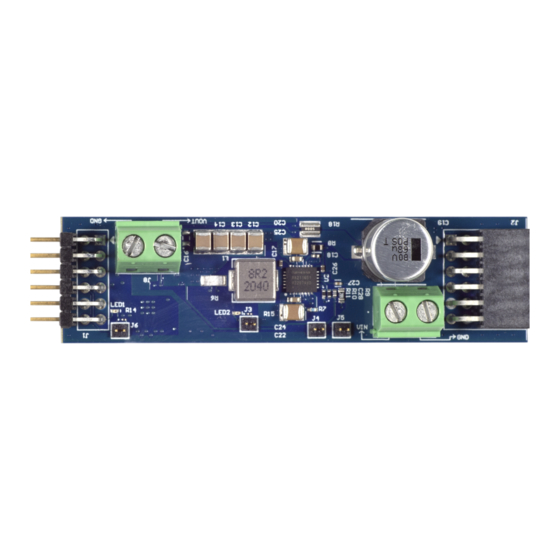
The QCIOT-5APWRPOCZ power board enables
quick prototyping of the
Quiescent Current Integrated Switching Regulator in
a custom system design. The
Digital Power Monitor is designed to measure and
control the regulator output of the RAA211651 with
margining.
The board provides a standard Pmod™ Type 6A
2
(extended I
C) connection for the on-board sensor to
plug into any required MCU evaluation kit with a
matching connector. The QCIOT-5APWRPOCZ
features Pmod connectors on both sides of the board
to allow additional Type 6/6A boards to connect in a
daisy-chained solution with multiple devices on the
same MCU Pmod connector.
The software support that is included with the
2
Renesas IDE
(e
studio) provides code generation
to connect the device and the MCU so that
development time is significantly reduced. With its
standard connector and software support, the
QCIOT-5APWRPOCZ is ideal for the Renesas
Quick-Connect IoT to rapidly create an IoT system.
R15UH0010EU0105 Rev.1.05
May 29, 2024
RAA211651
60V 5A Low
ISL28023
Precision
Figure 1. QCIOT-5APWRPOCZ Image
Evaluation Board Manual
Features
▪ 4.5V to 60V input supply range
▪ Adjustable output voltage (0.8V to 3.3V)
▪ Variable load current, up to 5A
▪ ∆∑ADC, 16-bit native resolution
▪ System voltage/current monitoring with efficiency
reporting
▪ Overvoltage/undervoltage and current fault
monitoring with 500ns detection delay
▪ Standardized type 6A Pmod connector supports
2
I
C extended interface
▪ Dual connectors allow pass-through signals for
daisy-chained solutions
▪ Software support in e
development time with one-click code generation
Board Contents
▪ QCIOT-5APWRPOCZ
© 2022-2024 Renesas Electronics
2
studio minimizes
Page 1
Advertisement
Table of Contents

Related Manuals for Renesas QCIOT-5APWRPOCZ


Summary of Contents for Renesas QCIOT-5APWRPOCZ
- Page 1 MCU so that development time is significantly reduced. With its ▪ QCIOT-5APWRPOCZ standard connector and software support, the QCIOT-5APWRPOCZ is ideal for the Renesas Quick-Connect IoT to rapidly create an IoT system. Figure 1. QCIOT-5APWRPOCZ Image R15UH0010EU0105 Rev.1.05...
-
Page 2: Table Of Contents
QCIOT-5APWRPOCZ Evaluation Board Manual Contents Functional Description ..............3 Operational Characteristics . -
Page 3: Functional Description
QCIOT-5APWRPOCZ Evaluation Board Manual Functional Description The QCIOT-5APWRPOCZ is intended as a quick connect prototyping solution for a switching buck regulator and digital power monitoring. This board can enable the designer to quickly evaluate applications where higher voltage and current supply from USB power is required. The QCIOT-5APWRPOCZ takes external voltages between 4.5V to 60V and can deliver up to 5A to an external load. -
Page 4: Operational Characteristics
QCIOT-5APWRPOCZ Evaluation Board Manual Operational Characteristics The QCIOT-5APWRPOCZ can be used as a starting point for DC power distribution, whether in high voltage industrial or battery powered applications. The board has been designed to the following specifications: ▪ Input voltage range = 4.5V - 60V ▪... -
Page 5: Setup And Configuration
If no Type 6A Pmod is available, ensure that the MCU evaluation kit can use the US082-INTERPEVZ interposer board. Insert the board into the MCU connector before adding any sensor boards. 2. Plug in the QCIOT-5APWRPOCZ to the Type 6A connector. Be careful to align Pin 1 on the sensor board and MCU kit. -
Page 6: I 2 C Address Select
Apply VIN between 4.5V to 60V. 5. The device is now ready to be used in the system. Follow the MCU kit instructions for connecting and powering up the evaluation kit. Figure 3. QCIOT-5APWRPOCZ with FPB-RA4E1 MCU Kit 1.2.3 C Address Select... -
Page 7: Schematic Diagrams
QCIOT-5APWRPOCZ Evaluation Board Manual Figure 5. QCIOT-5APWRPOCZ Image (Bottom) Schematic Diagrams Figure 6. CIOT-5APWRPOCZ Schematic R15UH0010EU0105 Rev.1.05 Page 7 May 29, 2024... - Page 8 QCIOT-5APWRPOCZ Evaluation Board Manual VBUS VINM 0.1uF VINP VBUS 0.1uF 0.1uF 0.1μF NC_1 GND_1 I2CVCC I2CVCC AUXP AUXM SMBCLK AUXV DAC_OUT DAC_OUT GND_2 I2C Address: 100nF Binary: 1011 111(0/1) 7-bit: 0x5F ISL28023FR60Z-T 8-bit: 0xBE/F 100nF 100nF SMBCLK SMBALERT2 SMBDAT SMBALERT1 Figure 7.
-
Page 9: Bill Of Materials
QCIOT-5APWRPOCZ Evaluation Board Manual Bill of Materials Reference Manufacturer Description Manufacturer Designator Part Number C1, C2, C3 CAP CER 0805 0.1UF 63V X7R 10% KEMET C0805C104KMREC7800 C4, C29, C30, CAP CER 0.1UF 10V X7R 0603 KEMET C0603C104M8RAC7867 C5, C6, C7, CAP CER 0.1UF 16V X7R 0402... -
Page 10: Board Layout
QCIOT-5APWRPOCZ Evaluation Board Manual Reference Manufacturer Description Manufacturer Designator Part Number Power Supply Controller Digital Power Monitor 24- Renesas Electronics ISL28023FR60Z-T QFN (4x4) America Inc Buck Switching Regulator IC Positive Adjustable Renesas Electronics RAA2116514GNP#HA0 0.8V 1 Output 5A 28-VFQFN Exposed Pad... -
Page 11: Typical Performance Graphs
QCIOT-5APWRPOCZ Evaluation Board Manual Typical Performance Graphs 4.5V 4.5V Load Current (A) Load Current (A) Figure 17. Efficiency Figure 18. Load Regulation 3.34 3.33 3.32 3.31 3.30 3.29 3.28 3.27 Input Voltage (V) Figure 19. Line Regulation R15UH0010EU0105 Rev.1.05 Page 11... -
Page 12: Software Design
QCIOT-5APWRPOCZ Evaluation Board Manual Software Design The following sections give an overview of the software implementation for the QCIOT-5APWRPOCZ, which is based on the Renesas RA Family's Flexible Software Package (FSP). These sections detail the project's code structure, the system's software modules, and the main system flow. Information such as the software API, pin functions, and fault handling is also provided. -
Page 13: Software Module Overview
QCIOT-5APWRPOCZ Evaluation Board Manual hal_entry.c system.c system.h dpm.c dpm.h DRIVER dpmProfile.h FSP DRIVERS Figure 21. Code Dependency Graph Software Module Overview The system module contains the main system algorithm that is described in the main system flow; this module is responsible for initializing and setting up the driver that is used in the main algorithm. -
Page 14: Algorithm Flowchart
QCIOT-5APWRPOCZ Evaluation Board Manual 4.2.2 Algorithm Flowchart Figure 22 describes the algorithm at a high level. sys_main() dpm_init() dpm_setup() check_input_threshold() set_half_scale_value() user_input() adjust_dac_out() check_connection() DIFF < 1mV DIFF > 1mV dpm_update() get_LSB_and_set_E3() set_vol_margin() DIFF < 1mV IF DIFF > 1mV LSB <... - Page 15 QCIOT-5APWRPOCZ Evaluation Board Manual The functions outlined in Figure 22 are described as follows: ▪ sys_main() • Calls dpm_init() function • Calls dpm_setup() function • Calls check_input_threshold() function() • Calls user_input() function • Calls check_connection() function • Calls dpm_update() function •...
- Page 16 QCIOT-5APWRPOCZ Evaluation Board Manual ▪ dpm_set_dac_out() • Calls the dpm_set_half_scale_value() function ◦ Calls the dpm_cal_Vdac() function to calculate Vdac ◦ Depending on the Vdac value the half scale range is set ◦ Voltage margin is set and configure accordingly • Calls the adjust_dac_out() function.
-
Page 17: Hierarchy Chart
DAC voltage; this process is achieved using check_input_threshold() and user_input() function calls, respectively. If any faults occur at the input side, the faults are displayed on the Renesas Debug Virtual Console; if the faults are on the output side, the system shuts down. User Settings 4.3.1... - Page 18 QCIOT-5APWRPOCZ Evaluation Board Manual Figure 24. Profile Header Files The user settings and their usage are outlined in the Table 1. The user can adjust these values to fit the end application. Note: Some register settings adhere to multiple settings, and those settings are not fully listed. Refer to the datasheet for more information.
-
Page 19: Set Output Dac Voltage
▪ Changed orderable part number to QCIOT-5APWRPOCZ from QCIOT-006. ▪ Updated Figure Figure 4 Figure 1.02 Jan 4, 2024 ▪ Replaced “QCIOT-006 Power Board” with “QCIOT-5APWRPOCZ” throughout the document. 1.01 Jun 21, 2023 Product changed from QCIOT-5APWRPOCZ to QCIOT-5APWRPOCZ. 1.00 Dec 20, 2022 Initial release R15UH0010EU0105 Rev.1.05... - Page 20 Renesas' products are provided only subject to Renesas' Terms and Conditions of Sale or other applicable terms agreed to in writing. No use of any Renesas resources expands or otherwise alters any applicable warranties or warranty disclaimers for these products.
- Page 21 Mouser Electronics Authorized Distributor Click to View Pricing, Inventory, Delivery & Lifecycle Information: Renesas Electronics QCIOT-5APWRPOCZ...
Need help?
Do you have a question about the QCIOT-5APWRPOCZ and is the answer not in the manual?
Questions and answers