Table of Contents
Advertisement
Quick Links
QCIOT-COMPMPOCZ
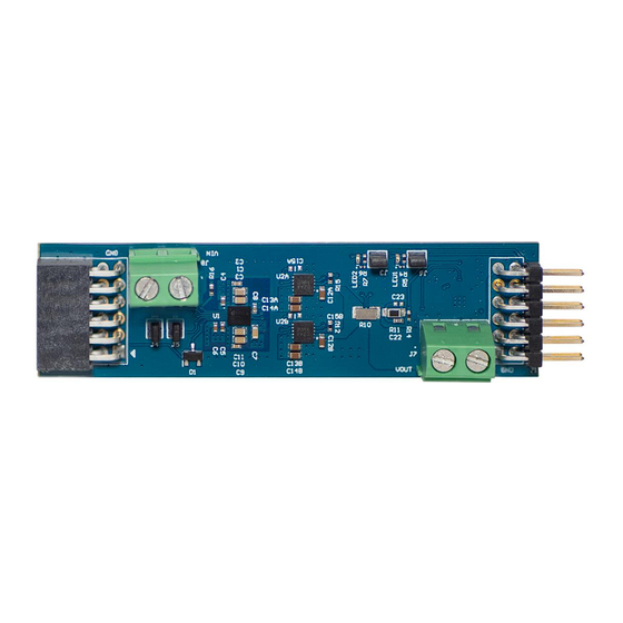
The QCIOT-COMPMPOCZ power board enables
quick prototyping of both the DA9313, a 5.5V to 10.5V
10A inductor-less power converter with power
efficiency up to 98%, and the ISL80103, a low voltage
6V, high-current 3A single-output LDO in a custom
system design. The ISL28025, a precision digital
power monitor, measures and controls the regulator
output of the ISL80103 with margining.
The board provides a standard Pmod™ Type 6A
2
(extended I
C) connection for the on-board sensor to
plug into any required MCU evaluation kit with a
matching connector. The QCIOT-COMPMPOCZ
features Pmod connectors on both sides of the board
to allow additional Type 6/6A boards to connect in a
daisy-chained solution with multiple devices on the
same MCU Pmod connector.
The software support that is included with the
2
Renesas IDE
(e
studio) provides code generation to
connect the device and the MCU so that the
development time is significantly reduced. With its
standard connector and software support, the
QCIOT-COMPMPOCZ is ideal for the Renesas
Quick-Connect IoT to rapidly create an IoT system.
R15UZ0010EU0100 Rev.1.00
Jun 10, 2024
Features
▪ 5.6 to 10.6V input supply range
▪ Adjustable output voltage (1.8V to 5V)
▪ Variable load current, up to 3A
▪ ∆∑ADC, 16-bit native resolution
▪ System voltage/current monitoring
▪ Overvoltage/undervoltage and current fault
▪ Battery power conversion with up to 98% efficiency
▪ Standardized type 6A Pmod connector supports
▪ Dual connectors allow pass-through signals for
▪ Software support in e
Figure 1. QCIOT-COMPMPOCZ Board
Evaluation Board Manual
monitoring with 500ns detection delay
2
I
C extended interface
daisy-chained solutions
2
development time with one-click code generation
© 2024 Renesas Electronics
studio minimizes
Page 1
Advertisement
Table of Contents

Subscribe to Our Youtube Channel
Related Manuals for Renesas QCIOT-COMPMPOCZ


Summary of Contents for Renesas QCIOT-COMPMPOCZ
- Page 1 MCU so that the development time is significantly reduced. With its standard connector and software support, the QCIOT-COMPMPOCZ is ideal for the Renesas Quick-Connect IoT to rapidly create an IoT system. Figure 1. QCIOT-COMPMPOCZ Board R15UZ0010EU0100 Rev.1.00...
-
Page 2: Table Of Contents
QCIOT-COMPMPOCZ Evaluation Board Manual Contents Functional Description ..............3 Operational Characteristics . -
Page 3: Functional Description
The QCIOT-COMPMPOCZ takes external voltages between 5.5V to 10.5V and can deliver up to 3A to an external load. A digital power monitor can monitor both input and output voltage. It can only monitor input current, and it can report diagnostics like power efficiency, peaks, and faults. -
Page 4: Operational Characteristics
QCIOT-COMPMPOCZ Evaluation Board Manual Operational Characteristics The QCIOT-COMPMPOCZ can be used as a starting point for providing low noise, high current regulated solution for sensitive applications like battery power banks, DSLR cameras, notebooks, tablets etc. The board has been designed to the following specifications: ▪... -
Page 5: Setup And Configuration
If no Type 6A Pmod is available, ensure that the MCU evaluation kit can use the US082-INTERPEVZ interposer board. Insert the board into the MCU connector before adding any sensor boards. 2. Plug in the QCIOT-COMPMPOCZ to the Type 6A connector. Be careful to align Pin 1 on the sensor board and MCU kit. -
Page 6: Board Design
QCIOT-COMPMPOCZ Evaluation Board Manual 5. The device is now ready to be used in the system. Follow the MCU kit instructions for connecting and powering up the evaluation kit. Figure 3. QCIOT-COMPMPOCZ with FPB-RA2E1 MCU Kit 1.2.3 C Address Select... -
Page 7: Schematic Diagrams
QCIOT-COMPMPOCZ Evaluation Board Manual Figure 5. QCIOT-COMPMPOCZ Evaluation Board (Bottom) Schematic Diagrams USB_VCC LED1 LED2 QBLP595-R QBLP595-R 1.5k 1.5k 4.7k 4.7k 4.7k 4.7k USB_VCC USB_VCC BUSY ENABLE RES_N ENABLE POWER_ON I2C_SCL POWER_ON GPIO4 I2C_SDA GPIO4 PMOD_6X2_RA_TH_SOCKET PMOD_6X2_RA_TH_Header 0.1μF 0.1μF 0.1μF Current sense resistor R1 needs to be Kelvin connected on layout. - Page 8 QCIOT-COMPMPOCZ Evaluation Board Manual 100nF VINM 100nF VINP VREG_IN 100nF ISL28025FR12Z VBUS VBUS I2CVCC I2CVCC GND_1 SMBCLK AUXV AUXV DAC_OUT DAC_OUT NC_1 GND_2 I2C Address: Binary: 1011 111(0/1) 7-bit: 0x5F 8-bit: 0xBE/F SMBALERT2 SMBALERT1 SMBDAT SMBCLK Figure 7. ISL28025 Digital Power Monitor Schematic...
-
Page 9: Bill Of Materials
QCIOT-COMPMPOCZ Evaluation Board Manual VOUT VOUT_1 ENABLE VOUT_2 SENSE/ADJ VIN_1 10μF VIN_2 EPAD 10μF ISL80103IRAJZ-TK Figure 9. ISL80103 LDO Schematic Bill of Materials Reference Manufacturer Description Manufacturer Designator Part Number C1, C3, C7, 0603 6.3V 47µF ±20% Tolerance X5R SMT... -
Page 10: Board Layout
QCIOT-COMPMPOCZ Evaluation Board Manual Reference Manufacturer Description Manufacturer Designator Part Number Chip LED 0402, Red, 0.02A, 2.0 to 2.5V, -40 to LED1, LED2 QT-Brightek QBLP595-R 80°C, 2-Pin SMD, RoHS, Tape and Reel Chip Resistor, 10Ω, ±1%, 63mW, -55 to 155°C,... -
Page 11: Typical Performance Graphs
QCIOT-COMPMPOCZ Evaluation Board Manual Figure 16. Bottom Layer Figure 17. Bottom Overlay Typical Performance Graphs 3.40 3.40 3.35 3.35 3.30 3.30 3.25 3.25 3.20 3.20 3.15 3.15 6.8V 0.5A 3.10 3.10 6.9V 1.5A 2.5A 3.05 3.05 3.00 3.00 Input Voltage (V Load Current (A) Figure 18. -
Page 12: Software Design
The following sections give an overview of the software implementation for the QCIOT-COMPMPOCZ, which is based on the Renesas RA Family's Flexible Software Package (FSP). These sections detail the code structure of the project, the system software modules, and the main system flow. Information such as the software API, pin functions, and fault handling is also provided. -
Page 13: Software Module Overview
QCIOT-COMPMPOCZ Evaluation Board Manual hal_entry.c ra_isl28025.c rm_isl28025.c rm_isl28025.h rm_isl28025_api.h rm_common_i2c rm_ioport FSP Driver rm_i2c_master Figure 22. Code Dependency Graph Software Module Overview The ra_isl28025 module contains the main system algorithm that is described in the main system flow. This module is responsible for initializing and setting up the driver that is used in the main algorithm. Also, this module makes calls to the other modules to initialize and setup. - Page 14 The main program runs once to get the DPM readings by isl28025_update_reading() function calls. The Vbus, Vshunt, Current, power, Temperature, Vaux, Peak Max Current, and Peak Min Current are displayed in the Renesas Debug Virtual Console if in debug mode. R15UZ0010EU0100 Rev.1.00...
- Page 15 QCIOT-COMPMPOCZ Evaluation Board Manual 4.2.2.2 start_isl28025_demo() Figure 24. Algorithm Flowchart The functions outlined in Figure 24 are described as follows: start_isl28025_demo() ▪ Calls isl28025_update_reading() function ▪ Calls isl28025_print_reading() function ▪ Calls check_output_threshold() function ▪ Calls set_reg_vol_to() function ▪ Calls check_connection() function ▪...
- Page 16 QCIOT-COMPMPOCZ Evaluation Board Manual • Read Vbus, Vshunt, Current, Power, Vaux, Temperature, Peak Max/Min Current and gets the status of the Vout Register for setting up the Input Threshold detection Isl28025_print_reading() ▪ Prints Vbus, Vshunt, Current, Power, Vaux, Temperature, Peak Max/Min Current of ISL28025 on the Rensas...
-
Page 17: User Settings
QCIOT-COMPMPOCZ Evaluation Board Manual 4.2.3 Hierarchy Chart Figure 25 outlines the hierarchy of function calls. start_isl28025_d emo() isl28025_update_reading() isl28025_print_reading() check_output_threshold() set_reg_vol_to() rm_isl28025_Read rm_isl28025_Read rm_isl28025_Read rm _isl28025_Read rm _isl28025_Read rm _isl28025_Read rm _isl28025_Read rm _isl28025_Read rm _isl28025_Read dpm_set_dac_out() PeakMaxCurrent() Vaux() PeakMinCurrent() -
Page 18: Ordering Information
QCIOT-COMPMPOCZ Evaluation Board Manual 4.3.2 Set Output DAC Voltage The set_reg_vol_to(USER_VOLTAGE) API sets the output voltage. The dropout voltage of the LDO ISL80103 is significantly less than 120mV at a maximum current of 3A. Ensure the difference between the Input voltage and the required output voltage is minimal so that the LDO is effective. - Page 19 Renesas' products are provided only subject to Renesas' Terms and Conditions of Sale or other applicable terms agreed to in writing. No use of any Renesas resources expands or otherwise alters any applicable warranties or warranty disclaimers for these products.
Need help?
Do you have a question about the QCIOT-COMPMPOCZ and is the answer not in the manual?
Questions and answers