
Subscribe to Our Youtube Channel
Related Manuals for Azbil NEW 10-III ACT


Summary of Contents for Azbil NEW 10-III ACT
- Page 1 CM2-ACT100-2002 NEW 10-III Electric Single-Seated Control Valve Model ACT User's Manual...
- Page 2 In no event shall Azbil Corporation be liable to anyone for any indirect, special or consequential damages. This information and specifications in this document are subject to change without notice.
- Page 3 Safety Precautions Symbols Safety precautions are for ensuring safe and correct use of this product, and for preventing injury to the operator and others or damage to property. Be sure to observe these safety precautions. Various symbols appear in this document. Their meaning is explained below.
- Page 4 Precautions for Safe Operation WARNING Before starting to work, check that the pressure in the pipes has dropped to atmospheric pressure. Otherwise, if fluid spews out, injury may result. CAUTION Do not stand on the device or use it as a step. There is a risk of falling. Do not touch the device unnecessarily while it is operating.
- Page 5 Handling Precautions Installation Precautions WARNING If the rated pressure or standards for connection are ignored when this device is used, damage to the product or leakage may cause a serious accident. When connecting the valve to the piping, do not put your hand or foot under the valve or between flanges.
- Page 6 Handling Precautions: • Avoid installing the valve where it will be subject to vibration or other external forces that may affect its performance. • Protective covers are attached to the flanges to protect the gasket-contacting surfaces and to prevent foreign matter from entering the valve. When installing the valve, remove the covers.
- Page 7 Precautions for Air Supply Piping and Electrical Work CAUTION For air supply, use pipes with an appropriate internal diameter so that pressure will not drop while the valve is operating. Failure to do so may result in poor valve performance. Wiring should be carried out only by qualified technicians and should comply with local electrotechnical standards.
- Page 8 Precautions for Assembly and Disassembly WARNING Before starting work, clean the inside of the valve, replace any residual gas, etc. Otherwise, residual fluid may cause an injury. Because damaged or corroded bolts and nuts may damage the valve and cause injury, replace them with new ones.
- Page 9 Close Open Close valve Close valve pressure pressure Follow the assembly procedure Replace the packing and gasket Tighten bolts to speci ed torque Packing Gasket...
- Page 10 Precautions for Maintenance WARNING If fluid leakage from the valve is found, stay away from the valve until safety can be confirmed. Depending on the properties of the fluid, a serious accident or injury may result. CAUTION Check the gland daily, and tighten the packing if leakage is found. Check valve operation daily, including a visual check for hunting.
- Page 11 Unpacking and Storing the Product Unpacking This valve is a precision instrument. Take special care in handling the valve to prevent accidents, damage, etc. When unpacking, check for the following items. • The valve, actuator, and parts to be attached •...
- Page 12 Inquiries For inquiries concerning this device, contact the azbil Group. When making an inquiry, have your model number and product number ready. Precautions for Storage Observe the following precautions in order to store the purchased valve properly. • If the valve is packed in a cardboard box, store it indoors at room temperature and humidity.
-
Page 13: Table Of Contents
Table of Contents Chapter 1. Structure of the Control System ........1-1 1-1. -
Page 15: Chapter 1. Structure Of The Control System
Chapter 1. Structure of the Control System 1-1. Introduction The NEW10-III is a control valve that is operated by relay contact input, potentiometer input, or 4–20 mA DC signals. Figure 1-1 illustrates a typical control valve system. Relay contacts, potentiometer, 4–20 mA DC signals Host control system Fluid... -
Page 16: Control Valve Structure
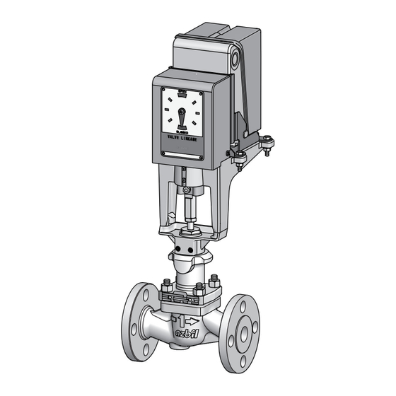
1-2. Control Valve Structure This device is composed of a valve body and an actuator. The valve body consists of a valve, bonnet, valve plug, and other components. The actuator consists of a control motor, yoke, and other components. Fig 1-2 illustrates the structure of this device. Control motor Actuator Linkage... -
Page 17: Specifications Of The Control Valve
1-3. Specifications of the Control Valve CAUTION The specifications of the control valve, such as the rated pressure and material of the valve body and trim material, are determined by the fluid conditions. The control valve must not be used for applications other than the application the valve is designed for. Failure to comply with this caution may result in burns or injuries due to high temperature or leakage of hazardous fluid. -
Page 19: Chapter 2. Installation
Chapter 2. Installation 2-1. Installation Location Please observe the following cautions when selecting the installation site for the control valve. CAUTION Make sure that there is a straight pipe section at least 10 times the pipe diameter on the upstream side and 6 times the pipe diameter on the downstream side (D: nominal diameter). -
Page 20: Inspection Before Installation
The control valve is designed to withstand severe operating conditions. However, in order to achieve its optimal performance, install the valve to a location with the following conditions: • Ambient temperature: -20 to +60 °C • Relative humidity: 5 to 95 % RH (without condensation) •... - Page 21 Check the following before installing the model ACT control valve on the piping. 1. The specifications printed on the name plate are appropriate for the use. 2. There is no damage to the valve (including the actuator and auxiliary equipment). 3.
-
Page 22: Installation On The Pipe
2-3. Installation on the Pipe <Installation> CAUTION Check that the pipes on both sides of the valve are properly aligned. Misalignment of the pipes will put a strain on the valve and may cause fluid leakage from the connections (gaskets). Check that the distance between the pipe flanges is equal to the total of the face-to-face length of the valve and the thickness of the gaskets. - Page 23 (1) Standard installation Fig 2-1 illustrates standard installation. Control valve Gasket Bolt Pipe Fig 2-1. Installation on the pipe...
- Page 24 (2) Installation procedure Step Procedure Check that the flow direction of the process fluid is the same as the direction indicated on the control valve. Flow direction indicated on the valve Fluid ow direction Fig 2-2. Flow direction indicated on the valve Attach the valve and gaskets to the pipes.
-
Page 25: Wiring
2-4. Wiring CAUTION Wiring should be carried out only by qualified technicians and should comply with local electrotechnical standards. Cabling should be carried out in accordance with facility conditions. Use an adapter (and packing) whose size is appropriate for the outer diameter of the cable. Avoid doing wiring work on a rainy day or in high humidity. - Page 26 ● Relay contact input (power: 24 V AC) Model number: ECM3000D0__0 ECM3000F0__0 L: Operation direction: CCW (counterclockwise) R: Operation direction: CW (clockwise) Handling Precautions: • For on-off operation, terminals 4, 5, and 6 are not used. ● Potentiometer (135 Ω) input (power: 24 V AC) Model number: ECM3000E0_ _0 AC24V...
- Page 27 ● 4–20 mA input (power: 85–264 V AC) Model number: ECM3000G9_ _0 + − AC85~264V DC4~20mA F.G. Note: The 4–20 mA input circuit and the power supply circuit are isolated.
-
Page 28: Inspection After Installation And Precautions For Operation
2-5. Inspection after Installation and Precautions for Operation <Cautions> • Make sure that the bolts and nuts of the bonnet, etc., are firmly tightened. • An increase in the valve’s temperature should be made gradually (100 °C / hr or less). Avoid operating the valve while its temperature is increasing. -
Page 29: Chapter 3. Operation
Chapter 3. Operation 3-1. Trial-Run Inspection and Adjustment (1) Operation test For models that operate on 4–20 mA DC input, send dummy input signals (0 to 100 %) to the device to check that the valve travel indicated in the specifications is achieved. * Page 1-1... -
Page 30: Troubleshooting
3-2. Troubleshooting Problems that might occur during operation are described in Table 3-1. Take necessary measures such as replacing parts, depending on the circumstances. Table 3-1. Control valve problem causes and countermeasures Phenomenon Cause Countermeasure The valve hunts near the The valve capacity is too large. - Page 31 Table 3-1. Control valve problem causes and countermeasures (continued from the previous page) Phenomenon Cause Countermeasure The valve stem is at the The valve plug and/or the seat ring · Lap the valve plug and seat valve fully-open position. is corroded, eroded, abraded, or ·...
-
Page 33: Chapter 4. Maintenance
Chapter 4. Maintenance 4-1. Inspection of the Control Valve Check the control valve in accordance with the following instructions in order to maintain proper performance, prevent accidents, and detect problems early. Daily inspection and periodic inspection (overhaul) must be carried out. For instructions on handling the ECM3000 control motor, refer to the user’s manual indicated in chapter 1. -
Page 34: Periodic Inspection
4-1-2. Periodic Inspection Disassemble the control valve once every two or three years. Replace consumables and repair or replace any parts that have deteriorated. When disassembling the valve, be sure to observe the instructions in 4-3. Disassembling and Reassembling the Control Valve. <... -
Page 35: Removing The Control Valve
CAUTION Dispose of old parts that were replaced during valve disassembly or maintenance as industrial waste. If they are burned or discarded carelessly, environmental pollution will result. 4-2. Removing the control valve This section provides instructions for removing the control valve from the equipment for a periodical inspection or other purposes. - Page 36 (2) Removal from the piping Secure the control valve by slinging or by other means. Then, remove bolts and nuts from the flanges and detach the control valve from the piping. CAUTION If the eyebolts (eyenuts) attached to the actuator are used to lift the valve, make sure that the weight does not exceed the limit specified in the user's manual.
-
Page 37: Disassembling And Reassembling The Control Valve
4-3. Disassembling and Reassembling the Control Valve This section gives instructions on disassembly and reassembly of the control valve. If you need to disassemble and reassemble the valve for periodic inspection, troubleshooting, or other circumstances, refer to the instructions. 4-3-1. Before Disassembly •... - Page 38 Stem connector screw Linkage Stem connector Stem connector screw Hex socket head set screws Hex nut Stem connector screw Matching marks Linkage Valve stem Stem connector Hex nut Valve stem Assembly dimension Fig 4-1. Disassembly and reassembly of the control valve...
-
Page 39: Disassembling The Valve Body
4-3-4. Disassembling the Valve Body < Precautions > • Disassemble the valve body on a rag, etc., to avoid damaging the valve. • After disassembling the valve body, protect the gasket-contacting surfaces, the valve plug seat, sliding areas, seat ring, etc. WARNING Before disassembling the valve body, check that the pressure in the valve has dropped to atmospheric pressure. - Page 40 Packing nut O-ring < V-shaped PTFE* packing > Packing holder V-shaped PTFE* packing Packing retainer Spring Packing ring < Valve material: SCS13A > < Valve material: SCPH2 > Bonnet Hex nut Bonnet Name plate Gasket Guide bushing Stud bolt Valve plug Seat ring Seat ring gasket (only for degreased models)
-
Page 41: Reassembling The Valve Body
(2) Removing the trim After removing the valve plug, remove the seat ring with the special wrench for the seat ring. (3) Taking out the gland parts Take out the gland parts with a pipe, etc. Take notes of the type, quantity, order, etc., of parts such as the packing and spacers in order to facilitate reassembly. - Page 42 Table 4-1. Seat ring tightening torque [Unit: N·m] Nominal size (inches) Seat ring tightening torque 1/2, 3/4, 1 1-1/2, 2 2-1/2, 3 Table 4-2. Bonnet hex nut tightening torque [Torque unit: N·m] Nominal size (inches) Bonnet hex nut Tightening torque 1/2, 3/4, 1 1-1/2, 2 2-1/2, 3...
- Page 43 (3) Assembling the valve plug and bonnet Step Procedure Apply an agent for preventing galling*1 to a new gasket and set the gasket on the valve in place. Insert the valve plug into the bonnet, then place the bonnet on the valve. Be sure to align the matching marks, which were placed before disassembly, in order to set the bonnet in the right position.
-
Page 44: Mounting The Actuator On The Valve Body
4-3-6. Mounting the Actuator on the Valve Body <Procedure> In addition to the following instructions, refer to Fig 4-1. (1) Attaching the stem connector Step Procedure Apply an anti-galling agent*1 to the valve stem. Screw the hex nut and stem connector onto the valve stem so that the dimension indicated in Fig 4-1 is achieved. -
Page 45: Chapter 5. Disposal
Chapter 5. Disposal If this device is no longer needed, dispose of it appropriately as industrial waste, in accordance with local regulations. Do not reuse all or a part of the device. -
Page 47: Chapter 6. Maintenance Information
List of parts Refer to List of Parts in Appendix B. Ordering Please contact the azbil Group and have the name and part number of the necessary parts ready. Maintenance service The azbil Group offers various service programs that provide the advantage of maintenance know-how accumulated over a long period. -
Page 49: Appendix A Dimension And Weight
Appendix A Dimension and Weight External dimensions and weight of the control valve are indicated in Table A-1. Note that dimensions and weight may vary depending on the optional specifications. (Unit: mm) Q455 C 115.5 Valve linkage Fig. A-1. Face-to-face dimension and external dimensions Table A-1. -
Page 51: Appendixb List Of Parts
Appendix B List of Parts 1. Valve plug (plug stem assembly) The valve plug and valve stem are united. 1-1. Valve plug (material: SUS316) Name Part No. Qty. 1/2 in., Cv = 0.4, %C, plug stem assembly, SUS316 82557807-01100 1/2 in., Cv = 0.63, %C, plug stem assembly, SUS316 82557807-02100 1/2 in., Cv = 1.0, %C, plug stem assembly, SUS316 82557807-03100... - Page 52 1-3. Valve plug (material: SUS316)(for PTFE soft seat) Name Part No. Qty. 1/2 in., Cv = 0.4, %C, plug stem assembly, SUS316 82557808-01100 1/2 in., Cv = 0.63, %C, Plug stem assembly, SUS316 82557808-02100 1/2 in., Cv = 1.0, %C, plug stem assembly, SUS316 82557808-03100 1/2 in., Cv = 2.5, %C, plug stem assembly, SUS316 82557808-04100...
- Page 53 2. Seat ring 2-1. Seat ring (material: SUS316) Name Part No. Qty. 1/2 in., Cv = 0.4, %C, seat ring, SUS316 82553264-02200 1/2 in., Cv = 0.63, %C, seat ring, SUS316 82553264-02200 1/2 in., Cv = 1.0, %C, seat ring, SUS316 82553264-03200 1/2 in., Cv = 2.5, %C, seat ring, SUS316 82553264-04200...
- Page 54 2-3. Seat ring (material: SUS316)(for PTFE soft seat) Name Part No. Qty. 1/2 in., Cv = 0.4, %T, seat ring, SUS316 82553928-20200 1/2 in., Cv = 0.63, %T, seat ring, SUS316 82553928-20200 1/2 in., Cv = 1.0, %T, seat ring, SUS316 82553928-30200 1/2 in., Cv = 2.5, %T, seat ring, SUS316 82553926-10200...
- Page 55 5. Gland parts 5-1. PTFE packing Key No. Name Part No. Qty. O-ring P10 AFLAS 82592220-80100 Packing nut 82509727-16600 O-ring P16 AFLAS 82592221-70100 Packing holder 82509735-10300 V-shape packing 82509736-10100 Packing retainer 82509737-10200 Spring 82509716-16600 Packing ring 82509714-16600...
-
Page 57: Appendix C Main Parts To Be Replaced
Appendix C Main Parts to be Replaced Parts of this control valve can be used for a long period of time, but the following parts should be replaced at every periodic inspection. Location: valve body Gland packing Gaskets... - Page 58 SJ/T11364...
- Page 60 1. Warranty period and warranty scope 1.1 Warranty period Azbil Corporation's products shall be warranted for one (1) year from the date of your purchase of the said products or the delivery of the said products to a place designated by you.
- Page 61 Although acceleration of the above situation varies depending on the conditions or environment of use of the products, you are required not to use any Azbil Corporation's products for a period exceeding ten (10) years unless otherwise stated in specifications or instruction manuals.
- Page 63 Document Number: CM2-ACT100-2002 Document Name: NEW 10-III Electric Single-Seated Control Valve Model ACT User's Manual Date: 1st edition : Aug. 2017 Issued/Edited by: Azbil Corporation...
Need help?
Do you have a question about the NEW 10-III ACT and is the answer not in the manual?
Questions and answers